Table of Contents
Advertisement
Advertisement
Table of Contents

Summary of Contents for Taurus RT1254
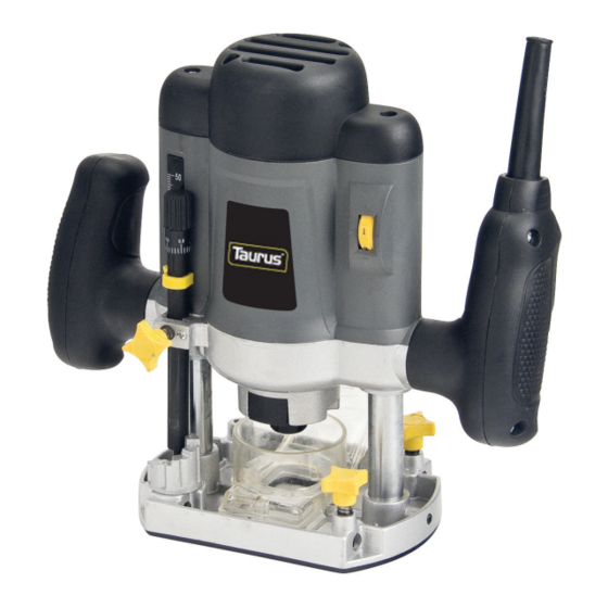
- Page 1 USER MANUAL 1200W ROUTER MODEL NO.: RT1254...
-
Page 2: Warranty & Service
WARRANTY & SERVICE AFTER SALES SUPPORT: TEL 1300 366 144 Model: RT1254 Description: 1200W Router Warranty Period: 12 Month Warranty What your 1 Year Warranty means: Great care has gone into the manufacture of this product and it should therefore provide you with years of good service when used properly. -
Page 3: Table Of Contents
INTRODUCTION Congratulations on choosing to buy this TAURUS product. All products brought to you by TAURUS are manufactured to the highest standards of performance and safety, and, as part of our philosophy of customer service and satisfaction, are backed by our comprehensive 1 Year Warranty. -
Page 4: Package Contents
PACKAGE CONTENTS Router machine, 1PC Rods, 2PCs Collets (1X 1/4”, 1X5/16”), Total 2PCs Pivot Rod Trammel, 1PC 15mm template follower, 1PC Spanner, 1PC Parallel Guide Fence, 1PC Dust Extraction Port, 1PC (already fixed on main machine) Instruction Manual, 1PC Warranty Stickers, 2PCs Warranty certificate, 1PC SPECIFICATIONS Rated Input:... -
Page 5: General Safety Information
GENERAL SAFETY INSTRUCTIONS When using electric tools basic safety precautions should always be followed to reduce the risk of fire, electric shock and personal injury. Read all these instructions before attempting to use the machine. 1. Consider the environment. Do not work in the rain. Do not work in damp or wet conditions. Do not use without adequate light. -
Page 6: Additional Safety Instructions
cord away from any sharp objects or heat source. 10. Damaged or dropped. Always inspect your table and supply cord before use. Do not use this equipment if it has been damaged, dropped, left outdoors or dropped in water. Return it to an authorized service dealer for examination and repair. - Page 7 not use a power tool while you are tired or under the influence of drugs, alcohol or medication. A moment of inattention while operating power tools may result in serious personal injury. b) Use safety equipment. Always wear eye protection. Safety equipment such as dust mask, non-skid safety shoes, hard hat, or hearing protection used for appropriate conditions will reduce personal injuries.
-
Page 8: Getting To Know Your Router
GETTING TO KNOW YOUR ROUTER 1. ON/OFF trigger switch 11. Height adjustment lock 2. Trigger safety button 12. Collet nut 3. Plunge lock level 13. Turret 4. Additional rod locking point (used in 14. Rods conjunction with 16) 5. Rod locking poin 15. -
Page 9: Assembly
ASSEMBLY Note: Remove the plug from the socket before carrying out adjustment, servicing or maintenance. PARALLEL GUIDE FENCE (Fig. 1) Attach the two face plates (a) to the parallel guide fence (B) with the four machine screws (C) supplied. Insert screw (D) through spring washer (E) and flat washer (F). -
Page 10: Operating Instructions
the size is not known insert the bit into the collet. The collet which offer a machine fit to the shank is the correct one to use. Do not force the bit into a collet. Replace the spring and place the collet into the spindle before loosely replacing the nut (H). - Page 11 SETTING THE CUTTING DEPTH (Figs. 6-8) With a suitable router bit fitted place the router on to the work piece. Rotate the turret (M) to the lowest position. Slowly plunge the router until the bit just touched the work piece. Lock the router in this position with the plunge lock level.
- Page 12 PARALLEL GUIDE ROUTING (Fig.9) Ensure the edge along which the guide is going to travel is smooth and true as any inconsistencies will translate into the cut. Pass the parallel guide rods through the four pointes in the router’s base and secure in place with lock knobs ®. When using the parallel guide an even pressure should be applied to each face except on a leading/trailing edge of a work piece.
-
Page 13: Trouble Shooting
TROUBLE SHOOTING NOTE: Remove the plug from the socket before carrying out adjustment, servicing or maintenance. PROBLEM POSSIBLE CAUSE REMEDY Motor does not start 1. Fuse 1. Replace/reset time delay fuse or circuit breaker 2. Brushes worn 2. Have brushes replaced by authorized service agent 3. -
Page 14: Explanation Of Symbols
EXPLANATION OF SYMBOLS Explanation Symbols Read operator’s manual Do not operate unit in rain Wear eye and ear protection Keep bystanders at least 5m away from unit during operation. Explanation of the safety signal words used in this manual: “Warning” signals a hazard that may cause serious injury or death if the recommended precautions are not followed.


Need help?
Do you have a question about the RT1254 and is the answer not in the manual?
Questions and answers