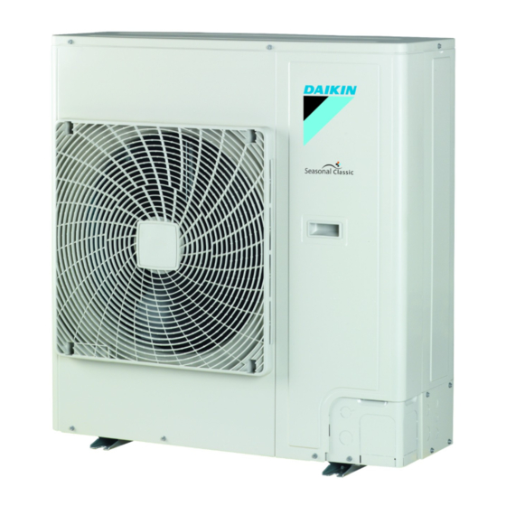
Summary of Contents for Daikin RZQSG71L3V1B
- Page 1 INSTALLATION MANUAL Split System air conditioners RZQSG71L3V1B RZQS71D7V1B RZQS71D2V1B RZQS100D7V1B RZQS125D7V1B RZQS140D7V1B...
- Page 2 B 2 B 2 D 2 D 2 D 2 D 2 L 1 L 1 B 1 B 1 L 2 L 2 D 1 D 1 B 2 B 2 D 2 D 2 D 2 D 2 L 1 L 1 B 1 B 1 L 2 L 2...
- Page 3 3P290872-13J...
- Page 4 3PW71102-4B...
-
Page 5: Table Of Contents
When wiring between the indoor and outdoor units, and wiring IF UNSURE OF INSTALLATION PROCEDURES OR USE, the power supply, form the wires so that the frontside panel can ALWAYS CONTACT YOUR DAIKIN DEALER FOR ADVICE be securely fastened. AND INFORMATION. -
Page 6: Before Installation
EFORE INSTALLATION Caution ■ Ground the air conditioner. Since maximum working pressure is 4.0 MPa or 40 bar, Grounding resistance should according national pipes of larger wall thickness may be required. Refer to regulations paragraph "Selection of piping material" on page Do not connect the earth wire to gas or water pipes, lightning conductor or telephone earth wire. -
Page 7: Selecting Installation Site
■ See the figure below for the location of the accessories. Turn the air outlet side toward the building's wall, fence or screen. Accessories Make sure there is enough room to do the installation Handling ■ As shown in the figure, bring the unit slowly by grabbing the left and Set the outlet side at a right angle to the direction of the wind. -
Page 8: Precautions On Installation
RECAUTIONS ON INSTALLATION NSTALLATION SERVICING SPACE ■ Check the strength and level of the installation ground so that The numerical figures used in here represent the dimensions for the the unit will not cause any operating vibration or noise after 71-100-125-140 class models. -
Page 9: Refrigerant Pipe Size And Allowable Pipe Length
Selection of piping material In case of installing multiple units (2 units or more) in lateral connection per row. ■ Piping and other pressure containing parts shall comply with the national and international codes and shall be suitable for refrigerant, use phosphoric acid deoxidised seamless copper for refrigerant. -
Page 10: Precautions On Refrigerant Piping
■ Allowable pipe length and height difference In order to prevent dirt, liquid or dust from entering the piping, cure the piping with a pinch or taping. See the table below concerning lengths and heights. Refer to figures 2, 3, and 5. - Page 11 ■ Preventing foreign objects from entering Closing the valve Place the hex wrench on the valve bar and turn clockwise. Plug the pipe through-holes with putty or insulating material Stop when the valve bar no longer turns. It is now closed. (procured locally) to stop up all gaps, as shown in the figure.
-
Page 12: Evacuating
■ Cautions for necessity of a trap Be sure to insulate the liquid and gas-side field piping and the refrigerant branch kit. Since there is fear of the oil held inside the riser piping flowing back into the compressor when stopped and causing liquid compression Any exposed piping may cause condensation or burns phenomenon, or cases of deterioration of oil return, it will be necessary if touched. -
Page 13: Charging Refrigerant
Procedure for leak test The filled out label must be adhered on the inside of the product and in the proximity of the product charging port (e.g. on the inside of the Leak test must satisfy EN378-2. service cover). Evacuate the pipes and check vacuum . - Page 14 Total charging weight of the refrigerant (after a leak, For twin, triple, and double twin system etc.) Please charge additionally according to the following calculation. The total charging amounts relate to the refrigerant piping length as (additional amount is R1+R2) "Maximum allowable piping length"...
-
Page 15: Electrical Wiring Work
Secure the wiring in the order shown below. LECTRICAL WIRING WORK Secure the ground wire to the stop valve attachment plate so that it does not slide. ■ All field wiring and components must be installed by a licensed electrician and must comply with relevant Secure the ground wire to the stop valve attachment plate one European and national regulations. -
Page 16: Test Operation
Precautions on wiring of power supply and inter-unit Specifications of standard wiring components wiring RZQSG71 RZQS71 RZQS100 RZQS125 RZQS140 ■ Use a round crimp-style terminal for connection to the power supply terminal board. In case it cannot be used due to Minimum circuit 21.2 18.9... -
Page 17: Disposal Requirements
Test run Failure diagnosis at the moment of first installation ■ Be sure to turn power on at least 6 hours before starting In case nothing is displayed on the remote controller (the current operation in order to protect the compressor. set temperature does not display), check for any of the following abnormalities before you can diagnose possible malfunction Make sure the liquid and gas stop valves are open. -
Page 18: Wiring Diagram
IRING DIAGRAM : Wire clamp : Black : Terminal : Green : Connector : Brown : Relay connector : Blue : Field wiring : Orange : Red : White : Yellow : Refer to the service manual for connecting wiring to X6A. : The position of the selector switches (DS1) indicate the factory setting. - Page 20 4P342104-1...


Need help?
Do you have a question about the RZQSG71L3V1B and is the answer not in the manual?
Questions and answers