Yaesu FT-450 Technical Supplement
Hf/50 mhz
Hide thumbs
Also See for FT-450:
- Operation manual (104 pages) ,
- User manual (32 pages) ,
- Brochure & specs (2 pages)
Table of Contents
Advertisement
Quick Links
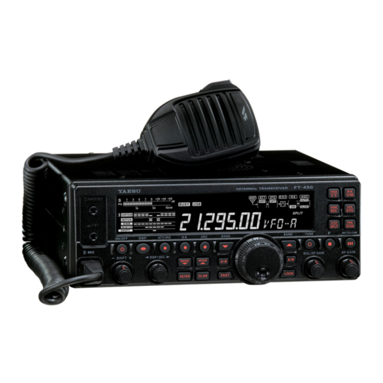
HF/50 MHz TRANSCEIVER
FT-450
Technical Supplement
©2007 VERTEX STANDARD CO., LTD.
Introduction
This manual provides technical information necessary
for servicing the FT-450 HF/50 MHz Transceiver.
Servicing this equipment requires expertise in handling
surface-mount chip components. Attempts by non-qual-
ified persons to service this equipment may result in per-
manent damage not covered by the warranty, and may
be illegal in some countries.
Two PCB layout diagrams are provided for each double-
sided circuit board in the Transceiver. Each side of is re-
ferred to by the type of the majority of components in-
stalled on that side ("leaded" or "chip-only"). In most
cases one side has only chip components, and the other
has either a mixture of both chip and leaded components
(trimmers, coils, electrolytic capacitors, ICs, etc.), or lead-
ed components only.
While we believe the technical information in this manu-
al to be correct, VERTEX STANDARD assumes no liabili-
ty for damage that may occur as a result of typographi-
cal or other errors that may be present. Your cooperation
in pointing out any inconsistencies in the technical infor-
mation would be appreciated.
VERTEX STANDARD CO., LTD.
4-8-8 Nakameguro, Meguro-Ku, Tokyo 153-8644, Japan
VERTEX STANDARD
US Headquarters
10900 Walker Street, Cypress, CA 90630, U.S.A.
YAESU EUROPE B.V.
P.O. Box 75525, 1118 ZN Schiphol, The Netherlands
YAESU UK LTD.
Unit 12, Sun Valley Business Park, Winnall Close
Winchester, Hampshire, SO23 0LB, U.K.
VERTEX STANDARD HK LTD.
Unit 5, 20/F., Seaview Centre, 139-141 Hoi Bun Road,
Kwun Tong, Kowloon, Hong Kong
VERTEX STANDARD ( AUSTRALIA ) PTY., LTD.
Normanby Business Park, Unit 14/45 Normanby Road
Notting Hill 3168, Victoria, Australia
EH024H90A
Exploded View & Miscellaneous Parts
Alignment
Board Unit (Schematics, Layouts & Parts)
RF-IF Unit
PANEL Unit
CNTL Unit
TUNER Unit ATU-450 (Option)
Contents
Advertisement
Table of Contents

Related Manuals for Yaesu FT-450


Summary of Contents for Yaesu FT-450
- Page 1 ©2007 VERTEX STANDARD CO., LTD. EH024H90A Introduction This manual provides technical information necessary for servicing the FT-450 HF/50 MHz Transceiver. Servicing this equipment requires expertise in handling surface-mount chip components. Attempts by non-qual- ified persons to service this equipment may result in per- manent damage not covered by the warranty, and may be illegal in some countries.
- Page 2 Specifications General Rx Frequency Range: 30 kHz - 56 MHz (operating) 160 - 6 m (specified performance, Amateur bands only) Tx Frequency Ranges: 160 - 6 m (Amateur bands only) Frequency Stability: ±1 ppm/hour (@+25 °C, after warmup) Operating Temperature Range: –10 °C ~ +50 °C Emission Modes: A1A (CW), A3E (AM), J3E (LSB, USB), F3E (FM), F2D (DTMF TONE)
- Page 3 Specifications Receiver Circuit Type: Double-conversion superheterodyne Intermediate Frequencies: 67.899 MHz / 24 kHz Sensitivity (IPO “OFF”, ATT: OFF): SSB (2.4 kHz, 10 dB S+N/N) 0.25 µV (1.8 - 2.0 MHz) 0.25 µV (3.5 - 30 MHz) 0.20 µV (50 - 54 MHz) AM (6 kHz, 10 dB S+N/N, 30 % modulation @400 Hz) 2.00 µV (1.8 - 2.0 MHz) 2.00 µV (3.5 - 30 MHz)
- Page 4 Specifications Note SPECIFICATIONS-3...
- Page 5 PANEL ASSY RA0900400 RA0900800 RUBBER RING KNOB RA0900800 KNOB RA0901800 U91408007 SPONGE RUBBER RA0898500 HEX SOCKET SCREW R6144801 BOTTOM CASE R3135000A WASHER T9318300 R0136380 WIRE ASSY(GRA 320 TMP/TMP) COIL SPRING S4000043 (X4 pcs) CASE LEG FT-450 Technical Supplement Exploded View-1...
- Page 6 Exploded View & Miscellaneous Parts FT-450 Technical Supplement Exploded View-2...
- Page 7 Block Diagram FT-450 Technical Supplement BLOCK DIAGRAM-1...
- Page 8 Connection Diagram CONNECTION DIAGRAM-1 FT-450 Technical Supplement...
- Page 9 Alignment Introduction and Precautions Required Test Equipment The following procedures cover adjustments that are RF Signal Generator not normally required once the transceiver has left AF Signal Generator the factory. However, if a problem occurs during Spectrum Analyzer good to at least 1 GHz. normal operation due to component failure;...
- Page 10 Alignment Reference Frequency RX IF Circuit (SSB/CW) Connect the Frequency Counter to TP2001 on the Set the following controls as indicated: RF-IF-Unit. [IPO]: OFF Adjust X2001 so that the Frequency Counter read- [ATT]: OFF ing is 22.625 MHz ±10 Hz. [RF GAIN] knob: Fully clockwise Connect the AF millivoltmeter and 4 Ohm 2nd Local Carrier Output Level...
- Page 11 Alignment J2002 TP2009 T2017 TP2001 T2022 T2018 L2066 L2067 T2020 X2001 T2019 T2021 TP2006 L2065 L2068 RF-IF U ALIGNMENT-3...
- Page 12 Alignment Final Stage Idling Current PA Unit Connect the DC ammeter to the lead of L5008. Preparation Press the PTT button; adjust VR5404 on the PA Connect the 50-Ohm Dummy Load and Wattme- Unit so the DC ammeter reading is 1.0 A ± 100 ter to the "ANT"...
- Page 13 Alignment TC5400 L5008 TP5430 VR5403 VR5401 J5004 VR5404 J5003 VR5402 VR5405 PA U ALIGNMENT-5...
- Page 14 Alignment ALC Adjustment Software Adjustment Connect the 50-Ohm Dummy Load and Wattme- Preparation ter to the "ANT" jack. Set the VFO frequency for each band as indicated: Press and hold in the [ATT IPO], [NB], and [AGC] PERATING REQUENCY buttons, while turning the radio on, to enter the General Band 1.200 MHz 1.8 MHz Band...
- Page 15 Alignment Power Adjustment (50 W) Power Adjustment (10 W) Connect the 50-Ohm Dummy Load and Wattme- Connect the 50-Ohm Dummy Load and Wattme- ter to the "ANT" jack. ter to the "ANT" jack. Press and hold in the [ATT IPO], [NB], and [AGC] Press and hold in the [ATT IPO], [NB], and [AGC] buttons, while turning the radio on, to enter the buttons, while turning the radio on, to enter the...
- Page 16 Set the [MODE] switch to "AM". Press the PTT switch, then rotate the [MAIN DIAL] Rotate the [DSP/SEL] knob to select the align- knob for 50 W on the PO meter of the FT-450. ment parameter "AM-CAR". Release the PTT switch.
- Page 17 Alignment Voltmeter Adjustment ATAS Controller Adjustment Press and hold in the [ATT IPO], [NB], and [AGC] Connect the Digital DC voltmeter (high-Z) to the buttons, while turning the radio on, to enter the "ANT" jack. alignment mode. Press and hold in the [ATT IPO], [NB], and [AGC] Adjust the DC Power Supply voltage is exactly buttons, while turning the radio on, to enter the 13.8 V.
- Page 18 Alignment Note ALIGNMENT-10...
- Page 19 RF-IF Unit Circuit Diagram FT-450 Technical Supplement RF-IF-1...
- Page 20 RF-IF Unit Note FT-450 Technical Supplement RF-IF-2...
- Page 21 (Q2005, 2011, 2012, 2014, 2016, 2017, 2019, HZM7.5NB3 2022, 2023, 2025) (D2031, 2055) 2SC3356 (R24) HZM5.6NB2 (Q2027) (D2063) 2SA1365 (Q2052) 2SA1602A (MF) 2SC4154 (E) (Q2048) (Q2062) ISA1602AM1(Lot.9-) (Q2048) HZM27WA (D 2061) DAP236U 2SJ125D (D2032, 2033) (Q 2058) FT-450 Technical Supplement RF-IF-3...
- Page 22 RF-IF Unit Parts Layout (Side B) FT-450 Technical Supplement RF-IF-4...
- Page 23 K22174231 C 2067 CHIP CAP. 39pF GRM1882C1H390JA01D K22174225 C 2068 CHIP CAP. GRM1882C1H5R0CZ01D K22174206 C 2069 CHIP CAP. 120pF GRM1882C1H121JA01D K22174237 C 2070 CHIP CAP. 120pF GRM1882C1H121JA01D K22174237 C 2071 CHIP CAP. 56pF GRM1882C1H560JA01D K22174229 FT-450 Technical Supplement RF-IF -5...
- Page 24 C 2141 CHIP CAP. 0.022uF GRM39B223K25PT K22144807 C 2143 CHIP TA.CAP. 10uF TEMSVA1A106M-8R K78100028 C 2144 CHIP CAP. 0.01uF GRM39B103K25PT K22144803 C 2145 CHIP CAP. 0.01uF GRM39B103K25PT K22144803 C 2146 CHIP CAP. 0.022uF GRM39B223K25PT K22144807 FT-450 Technical Supplement RF-IF -6...
- Page 25 C 2220 CHIP CAP. 0.022uF GRM39B223K25PT K22144807 C 2221 CHIP CAP. 0.022uF GRM39B223K25PT K22144807 C 2222 CHIP TA.CAP. 22uF TEMSVB21A226M-8R K78100029 C 2223 CHIP CAP. 0.022uF GRM39B223K25PT K22144807 C 2224 CHIP CAP. 0.022uF GRM39B223K25PT K22144807 FT-450 Technical Supplement RF-IF -7...
- Page 26 C 2295 CHIP CAP. 0.01uF GRM39B103K25PT K22144803 C 2296 CHIP CAP. 0.01uF GRM39B103K25PT K22144803 C 2297 CHIP CAP. 0.01uF GRM39B103K25PT K22144803 C 2298 CHIP CAP. 0.01uF GRM39B103K25PT K22144803 C 2299 CHIP CAP. 0.01uF GRM39B103K25PT K22144803 FT-450 Technical Supplement RF-IF -8...
- Page 27 G2070476 D 2018 SML-210MTT86 G2070524 D 2019 DIODE 1SV271(TPH3.F) G2070476 D 2020 DIODE 1SV271(TPH3.F) G2070476 D 2021 DIODE 1SV271(TPH3.F) G2070476 D 2022 DIODE 1SV271(TPH3.F) G2070476 D 2023 DIODE 1SV271(TPH3.F) G2070476 D 2024 DIODE 1SV271(TPH3.F) G2070476 FT-450 Technical Supplement RF-IF -9...
- Page 28 L 2029 CHIP COIL 0.47uH C2520C-R47G L1691302 L 2030 CHIP COIL 0.33uH C2520C-R33G L1691300 L 2031 CHIP COIL 0.22uH C2520C-R22G L1691298 L 2032 CHIP COIL 47uH LQH32MN470K23L L1690095 L 2033 CHIP COIL 18uH LQH32MN180K23L L1690090 RF-IF -10 FT-450 Technical Supplement...
- Page 29 Q 2018 2SK520-T2B K41 G3805207A Q 2019 TRANSISTOR 2SC2714Y(TE85R.F) G3327147Y Q 2020 TRANSISTOR 2SC3357-T2 RF G3333577F Q 2021 2SK520-T2B K41 G3805207A Q 2022 TRANSISTOR 2SC2714Y(TE85R.F) G3327147Y Q 2023 TRANSISTOR 2SC2714Y(TE85R.F) G3327147Y Q 2024 TRANSISTOR PDTC144EE G3070244 FT-450 Technical Supplement RF-IF -11...
- Page 30 J24185105 R 2035 CHIP RES. 1.8k 1/16W RMC1/16 182JATP J24185182 R 2036 CHIP RES. 100k 1/16W RMC1/16 104JATP J24185104 R 2038 CHIP RES. 1/16W RMC1/16 100JATP J24185100 R 2039 CHIP RES. 1/16W RMC1/16 101JATP J24185101 FT-450 Technical Supplement RF-IF -12...
- Page 31 J24185223 R 2110 CHIP RES. 5.6k 1/16W RMC1/16 562JATP J24185562 R 2111 CHIP RES. 3.3k 1/16W RMC1/16 332JATP J24185332 R 2112 CHIP RES. 1/16W RMC1/16 101JATP J24185101 R 2113 CHIP RES. 1/16W RMC1/16 221JATP J24185221 FT-450 Technical Supplement RF-IF -13...
- Page 32 R 2186 CHIP RES. 100k 1/16W RMC1/16 104JATP J24185104 R 2187 CHIP RES. 1/16W RMC1/16 153JATP J24185153 R 2188 CHIP RES. 4.7k 1/16W RMC1/16 472JATP J24185472 R 2189 CHIP RES. 4.7k 1/16W RMC1/16 472JATP J24185472 FT-450 Technical Supplement RF-IF -14...
- Page 33 L0022854 T 2023 COIL WIDE-TRANS. 3-317611 L0022478 T 2024 COIL WIDE-TRANS. 3-317611 L0022478 T 2025 COIL WIDE-TRANS. 3-317610 L0022479 T 2026 BALUN TRANSFOMERS #458DB-1616=P3 L0190246 T 2027 BALUN TRANSFOMERS #458DB-1616=P3 L0190246 TH2001 THERMISTOR 157-152-53009-TP G9090123 FT-450 Technical Supplement RF-IF -15...
- Page 34 VXSTD P/N VERS. LOT SIDE LAY ADR X 2001 TCXO 22.625MHz TTS01NS-P1 22.625MHZ H9500840 XF2001 XTAL FILTER MFT67N 67.899MHZ H1102406 SHIELD CASE (20X51) RA0830700 SHIELD CASE R0124120 SHIELD CASE COVER (20X51) RA0830800 CASE COVER R0124131 FT-450 Technical Supplement RF-IF -16...
- Page 35 PANEL Unit Circuit Diagram FT-450 Technical Supplement PANEL -1...
- Page 36 PANEL Unit Note FT-450 Technical Supplement PANEL-2...
- Page 37 PANEL Unit Parts Layout (Side A) FT-450 Technical Supplement PANEL -3...
- Page 38 (Q 3001, 3006, 3010, 3012) (Q 3003) (Q 3005) (Q 3007) (Q 3008) (Q 3009) TA75S01F(SA) 2SC1623 (L5) 2SB624 (BY3) NJM78L05UA (8C) (Q 3011) (Q 3014, 3015, 3016, 3017) (Q 3018, 3019, 3020, 3021) (Q 3022) FT-450 Technical Supplement PANEL-4...
- Page 39 D 3011 SSC-UBMGFRT722 G2071158 D 3012 19-213/S2C-AN1P2B/3T G2071096 D 3013 19-213/S2C-AN1P2B/3T G2071096 D 3014 19-213/S2C-AN1P2B/3T G2071096 D 3015 19-213/S2C-AN1P2B/3T G2071096 D 3016 19-213/S2C-AN1P2B/3T G2071096 D 3017 19-213/S2C-AN1P2B/3T G2071096 D 3018 SSC-UBMGFRT722 G2071158 D 3019 SSC-UBMGFRT722 G2071158 FT-450 Technical Supplement PANEL-5...
- Page 40 CHIP RES. 100k 1/16W RMC1/16S 104JTH J24189049 R 3045 CHIP RES. 1/16W RMC1/16 100JATP J24185100 R 3048 CHIP RES. 1/10W RMC1/10T 102J J24205102 R 3049 CHIP RES. 1/10W RMC1/10T 102J J24205102 : Please contact Vertex Standard FT-450 Technical Supplement PANEL-6...
- Page 41 RH96N74 23F B103 RY-7862 J60800285 VR3002 POT. RH96N74 23F B103 RY-7862 J60800285 VR3003 POT. RH96N74 23F B103 RY-7862 J60800285 X 3001 XTAL TSS-6035B 19.82MHz 19.820MHZ H0103262A LCD HOLDER RA0899500 SPONGE RUBBER (LCD) RA0899600 SPONGE RUBBER (LCD) RA089960A LIGHT GUIDE RA089970A FT-450 Technical Supplement PANEL-7...
- Page 42 Parts List DESCRIPTION VALUE TOL. MFR'S DESIG VXSTD P/N VERS. LOT SIDE LAY ADR REFLECTOR SHEET RA089980A REFLECTOR SHEET RA089980C INTER CONNECTOR RA0900000 LIGHT SHEET RA0919900 LIGHT SHEET (LG-BTM) RA0931100 TAPE (LCD) RA0940000 SHEET RA0947100 SHEET RA094710A FT-450 Technical Supplement PANEL-8...
- Page 43 CNTL Unit Circuit Diagram FT-450 Technical Supplement CNTL-1...
- Page 44 CNTL Unit Note FT-450 Technical Supplement CNTL-2...
- Page 45 MC2850 (A7) (D 4004) (D 4007, 4008) AK4528VF ADSP-BF531SBSTZ400 ES29LV400ET-70TGI 2SJ125D (JD) LA4425A CD4028BPWR (Q 4021) (Q 4024) (Q 4025, 4025) (Q 4035) (Q 4036) (Q 4006) Parts Layout (Side A) AK4550VT (Q 4026) ADM202EARU-REEL (Q 4037) FT-450 Technical Supplement CNTL-3...
- Page 46 CNTL Unit Parts Layout (Side B) FT-450 Technical Supplement CNTL-4...
- Page 47 GRM39B103K25PT K22144803 C 4081 CHIP TA.CAP. 10uF TEMSVA1A106M-8R K78100028 C 4082 CHIP CAP. 0.022uF GRM39B223K25PT K22144807 C 4083 CHIP CAP. 12pF GRM1882C1H120JA01D K22174213 C 4084 CHIP CAP. GRM1882C1H8R0DZ01D K22174209 C 4085 CHIP CAP. 430pF GRM1882C1H431JA01D K22174256 FT-450 Technical Supplement CNTL-5...
- Page 48 GRM39B223K25PT K22144807 C 4162 CHIP CAP. 0.001uF GRM188B11H102KA01D K22174809 C 4163 CHIP TA.CAP. 10uF TEMSVA1A106M-8R K78100028 C 4164 CHIP TA.CAP. 10uF TEMSVA1A106M-8R K78100028 C 4165 CHIP CAP. 0.22uF GRM188B11A224KA01D K22104801 C 4166 CHIP TA.CAP. TESVA1C105M1-8R K78120009 FT-450 Technical Supplement CNTL-6...
- Page 49 L 4005 M.RFC 100uH FLC32T-101J L1690227 L 4006 M.RFC 100uH FLC32T-101J L1690227 L 4007 M.RFC 100uH FLC32T-101J L1690227 L 4008 M.RFC 100uH FLC32T-101J L1690227 Q 4001 TD62783AFNG(5.S.EL) G1092700 Q 4002 M51945BFP-600C G1091990 Q 4003 UPC2933BT-E1-AZ G1094338 FT-450 Technical Supplement CNTL-7...
- Page 50 R 4043 CHIP RES. 1/16W RMC1/16 000JATP J24185000 R 4044 CHIP RES. 1/16W RMC1/16 331JATP J24185331 R 4045 CHIP RES. 1/16W RMC1/16 331JATP J24185331 R 4046 CHIP RES. 1/16W RMC1/16 331JATP J24185331 : Please contact Vertex Standard FT-450 Technical Supplement CNTL-8...
- Page 51 1/16W RMC1/16 221JATP J24185221 R 4117 CHIP RES. 1/16W RMC1/16 102JATP J24185102 R 4118 CHIP RES. 1/16W RMC1/16 102JATP J24185102 R 4119 CHIP RES. 1/16W RMC1/16 102JATP J24185102 R 4120 CHIP RES. 1/16W RMC1/16 102JATP J24185102 FT-450 Technical Supplement CNTL-9...
- Page 52 R 4168 CHIP RES. 4.7k 1/16W RMC1/16 472JATP J24185472 S 4001 SLIDE SWITCH SSSS22 N6090057 S 4002 SLIDE SWITCH SSSS22 N6090057 X 4001 XTAL TSS-6035B 19.82MHz 19.820MHZ H0103262A X 4002 XTAL OSC 36.864MHz TPS11XC 36.864MHZ H9500770 FT-450 Technical Supplement CNTL-10...
- Page 53 PA Unit Circuit Diagram FT-450 Technical Supplement PA-1...
- Page 54 PA Unit Note PA-2...
- Page 55 DTC114TE (04) (Q 5402) (Q 5403, 5405) PDTC144EE (08) DTD123TK DTD123YK (F62) (Q 5404) (Q 5406) (Lot.2-) (Q 5406, 5408) DTD123TK (Q 5408) (Lot.3-) TB6593FNG DAN202U (N) (Q 5409) (D 5018, 5019) Parts Layout (Side A) FT-450 Technical Supplement PA-3...
- Page 56 PA Unit Parts Layout (Side B) PA-4...
- Page 57 CHIP CAP. 82pF 200V GRM21B2C2D820JV01L K22230227 C 5155 CHIP CAP. 100pF 200V GRM21B2C2D101JV01L K22230228 C 5157 CHIP CAP. 200V GRM2192C2D5R0CY21D K22230207 C 5158 CHIP CAP. 33pF 200V GRM2192C2D330JV01D K22230222 C 5159 CHIP CAP. 33pF 200V GRM2192C2D330JV01D K22230222 FT-450 Technical Supplement PA-5...
- Page 58 K22174243 C 5305 CHIP CAP. 220pF GRM1882C1H221JA01D K22174243 C 5306 CHIP CAP. 220pF GRM1882C1H221JA01D K22174243 C 5309 CHIP CAP. 10pF 200V GRM2192C2D100JV01D K22230216 C 5310 AL.ELECTRO.CAP. 4.7uF EEE1HA4R7SR K48170025 C 5311 CHIP CAP. 0.1uF GRM188B11C104KA01D K22124805 FT-450 Technical Supplement PA-6...
- Page 59 K22231104 C 5481 CHIP CAP. 0.1uF GRM188B11C104KA01D K22124805 C 5486 CHIP CAP. 180pF GRM2162C1H181JA01D K22170241 C 5487 CHIP CAP. 180pF GRM2162C1H181JA01D K22170241 C 5490 CHIP CAP. 0.0068uF GRM40B682M50PT K22170815 C 5491 CHIP CAP. 0.0068uF GRM40B682M50PT K22170815 FT-450 Technical Supplement PA-7...
- Page 60 Q 5006 RD16HHF1 G3090148 Q 5007 RD16HHF1 G3090148 Q 5009 RD100HHF1-101 G3090151 Q 5010 RD100HHF1-101 G3090151 Q 5400 TA75S01F(TE85R.F) G1091593 Q 5401 PQ09TZ1U G1092599 Q 5402 TRANSISTOR DTC124GUA T106 G3070184 Q 5403 TRANSISTOR DTC114TE TL G3070225 PA-8 FT-450 Technical Supplement...
- Page 61 RMC1/16 223JATP J24185223 R 5442 CHIP RES. 6.8k 1/16W RMC1/16 682JATP J24185682 R 5443 SHUNT RES. 0.006 R006J J32009019 R 5444 CHIP RES. 330k 1/10W 0.5% RR1220R-334-D-T5 J24209231 R 5445 CHIP RES. 1/4W RMC1/4 000JATP J24245000 FT-450 Technical Supplement PA-9...
- Page 62 TH5400 THERMISTOR 112103-2 G9090043 VR5401 POT. 2.2k EVN-5ESX50BE3 J51811222 VR5402 POT. 2.2k EVN-5ESX50BE3 J51811222 VR5403 POT. 2.2k EVN-5ESX50BE3 J51811222 VR5404 POT. 2.2k EVN-5ESX50BE3 J51811222 VR5405 POT. 2.2k EVN-5ESX50BE3 J51811222 GROUND PLATE RA0415200 SHIELD PLATE (DC) RA0899000 FT-450 Technical Supplement PA-10...
- Page 63 TUNER Unit ATU-450 (Option) Circuit Diagram FT-450 Technical Supplement TUNER-1...
- Page 64 TUNER Unit ATU-450 (Option) Note FT-450 Technical Supplement TUNER-2...
- Page 65 TUNER Unit ATU-450 (Option) Parts Layout (Side A) L78M05T-TL BU2152FS (Q 6001) (Q 6002) FT-450 Technical Supplement TUNER-3...
- Page 66 TUNER Unit ATU-450 (Option) Parts Layout (Side B) FT-450 Technical Supplement TUNER-4...
- Page 67 COIL A1 6.5T16D1.6PEW R L0022787 L 6011 TOROIDAL COIL 2.6uH 2.60U T80-6 L0022789 L 6012 TOROIDAL COIL 4.1uH 4.10U T80-2 L0022790 L 6013 TOROIDAL COIL 4.1uH 4.10U T80-2 L0022790 Q 6001 L78M05T-TL G1091731 Q 6002 BU2152FS(TAPE) G1093942 FT-450 Technical Supplement TUNER-5...
- Page 68 NY-5W-K-IE DC5V M1190197 RL6022 RELAY DC5V NY-5W-K-IE DC5V M1190197 RL6023 RELAY DC5V NY-5W-K-IE DC5V M1190197 RL6024 RELAY DC5V NY-5W-K-IE DC5V M1190197 SHIELD CASE ASSY (TNR) RA0901500 SPONGE RUBBER (TNR) RA0901800 SHIELD PLATE (TNR) RA0901700 (PNL) RA0951800 FT-450 Technical Supplement TUNER-6...
- Page 69 Copyright 2007 VERTEX STANDARD CO., LTD. All rights reserved No portion of this manual may be reproduced without the permission of VERTEX STANDARD CO., LTD.
Need help?
Do you have a question about the FT-450 and is the answer not in the manual?
Questions and answers