Table of Contents
Advertisement
Quick Links
Installation and Operating Instructions for
Temperature Controller MTR 3000
Introduction
The microprocessor-based controller MTR 3000 is used for thermostatic temperature control. For this purpose, it has an input for a Pt 100 temper-
ature sensor.
The supply voltage for the controller is 230 V AC. The controller has three make contacts as its output.
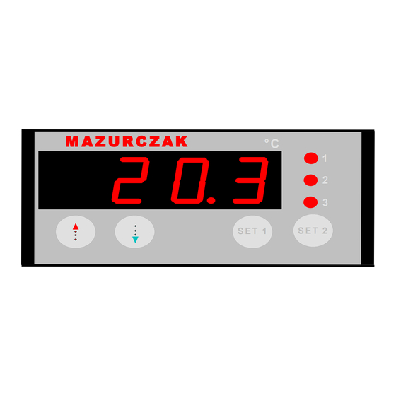
M A Z U R C Z A K
Description
By setting the appropriate parameters, the controller can be programmed to execute many different functions.
The controller is programmed in three levels with the aid of the buttons on its front panel. Access to parameters which affect the safety of the system
is deliberately made difficult.
The first level permits access only to the setpoint and the alarm acknowledgement.
All regulation parameters (P2 - P32) can be set in the second level.
The third level permits programming of the basic functions (A1 – A92) of the controller.
UP button (red arrow)
Down button (blue arrow)
SET 1 button
SET 1
SET 2 button
SET 2
Settings
First operating level
Displaying and adjusting the setpoints
The setpoint 1 (regulation contact 1) can be displayed by simply pressing the SET 1 button.
The setpoint 2 (regulation contact 2) can be displayed by simply pressing the SET 2 button.
With the Set button held down, the setpoint can be adjusted with the UP and DOWN buttons.
°C
1
2
3
S E T 1
S E T 2
This button is used to acknowledge an alarm.
Pressing this button displays set value S1.
If the button is not depressed, the actual value is displayed.
This button is also used for setting the parameters.
Pressing this button displays set value S2.
For details of changing the button assignments, see parameter A82 (standby mode, direct
switching of a contact).
WG 41/02.07/
D-MBA 373a
1
Advertisement
Table of Contents

Summary of Contents for Mazurczak MTR 3000
- Page 1 D-MBA 373a Introduction The microprocessor-based controller MTR 3000 is used for thermostatic temperature control. For this purpose, it has an input for a Pt 100 temper- ature sensor. The supply voltage for the controller is 230 V AC. The controller has three make contacts as its output.
-
Page 2: General Note
General note All values are stored in the non-volatile memory and are retained there even in the case of a power failure. When setting any value, always release the UP or DOWN button before releasing the SET button. This applies to the setpoint and all other parameters. Parameter/but Function Setting range... - Page 3 Fig. 1: Heating controller, asymmetrical hysteresis Fig. 2: Heating controller, symmetrical hysteresis Fig. 3: Cooling controller, asymmetrical hysteresis Fig. 4: Cooling controller, symmetrical hysteresis P4/P5 Lower/upper setpoint limit The setpoints S1/S2 (and P1) can be set only within the limits defined here. P6 Actual value correction The value set here is added to the measured value from the sensor.
- Page 4 Third operating level The third operating level can be accessed from the second level by scrolling through the parameter list until the last parameter (P32) is displayed and pressing the UP button for at least 10 seconds. The message "PA" then appears on the display. Release the button. Pressing the UP and DOWN keys together for at least four seconds then displays the parameter list for the third operating level (starting with A1).
- Page 5 Para- Function Setting range Default value Your meter setting Special function on alarm 0: Inactive 1: Display blinks 2: Buzzer sounds 3: Display blinks and buzzer sounds 4: As for 3, buzzer can be acknowledged 5: As for 4, buzzer sounds again after 10 minutes 6: As for 4, buzzer sounds again after 30 minutes...
- Page 6 Para- Function Setting range Default value Your meter setting Output connection, K1 0: No connection 1: Connect to regulation contact 1 2: Connect to regulation contact 2 3: Connect to alarm contact 4: Connect to buzzer function 5: Connect to button 3 or 5 Output connection, K2 0: No connection 1: Connect to regulation contact 1...
- Page 7 Fig. 5: Limit-value alarm, alarm contact normal Fig. 6:Bandwidth alarm, alarm contact normal A30=0: relative limits A30=2: relative limits A30=1: absolute limits A30=3: absolute limits Fig. 7: Limit-value alarm, alarm contact inverted Fig. 8:Bandwidth alarm, alarm contact inverted A30=4: relative limits A30=6: relative limits A30=5: absolute limits A30=7: absolute limits...
-
Page 8: Status Messages
A50 Minimum "On" time, regulation contact 1 A51 Minimum "Off" time, regulation contact 1 A52 Minimum "On" time, regulation contact 2 A53 Minimum "Off" time, regulation contact 2 These parameters make it possible to ensure that the output contact remains on or off for a specified time in order to reduce the switching frequency. The time specified here is the total minimum time for the on or off state of the contact (factory setting: 0 s). -
Page 9: Technical Data
Technical Data Measuring inputs: F1: Temperature sensor Pt100 (DIN IEC 751, three-wire connection), measuring range Pt100 (Class B): -60.0 °C...400 °C (with suitable sensor and <1 Ohm wire resistance), accuracy: +/- 0.5 K +/- 0.5% at 25 °C (not including any sensor errors), +/- 1K +/- 0.5% over the entire temperature range 0 to 55 °C (not including any sensor errors) Display and indicators: Three-digit red LED display, 13 mm high, for temperatures...
Need help?
Do you have a question about the MTR 3000 and is the answer not in the manual?
Questions and answers