Sign In
Upload
Download
Table of Contents
Contents
Add to my manuals
Delete from my manuals
Share
URL of this page:
HTML Link:
Bookmark this page
Add
Manual will be automatically added to "My Manuals"
Print this page
×
Bookmark added
×
Added to my manuals
Manuals
Brands
OTRONA Manuals
Laptop
ATTACHE
Technical manual
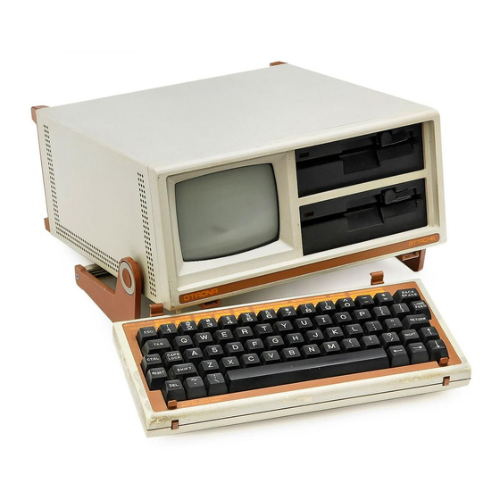
OTRONA Attache Technical Manual
Hide thumbs
Also See for Attache
:
Service manual
(79 pages)
1
2
3
4
Table Of Contents
5
6
7
8
9
10
11
12
13
14
15
16
17
18
19
20
21
22
23
24
25
26
27
28
29
30
31
32
33
34
35
36
37
38
39
40
41
42
43
44
45
46
47
48
49
50
51
52
53
54
55
56
57
58
59
60
61
62
63
64
65
66
67
68
69
70
71
72
73
74
75
76
77
78
79
80
81
82
83
84
85
86
87
88
89
90
91
92
93
94
95
96
97
98
99
100
101
102
103
104
105
106
107
108
109
110
111
112
113
114
115
116
117
118
119
120
121
122
123
124
125
126
127
128
129
130
131
132
133
134
135
136
137
138
139
140
141
142
143
144
145
146
147
148
149
150
151
152
153
154
155
156
157
158
159
160
161
162
163
164
165
166
167
168
169
170
171
172
173
174
175
176
177
178
179
180
181
182
183
184
185
186
187
188
189
190
191
192
193
194
195
196
197
198
199
200
201
202
203
204
205
206
207
208
page
of
208
Go
/
208
Contents
Table of Contents
Bookmarks
Table of Contents
Table of Contents
Attache System
Processor Board
Processor
Memory
I/O Rtc
Graphics
Serial
Expansion O~Ion
Display
Alphanumeric Display
Graphic Display
Standard Format
Keyboard
Multi-Function Keys
Power Supply
Setting the Voltage
System Block Diagram
Logic Overview
Processor Block Diagram
Central Processing Unit
Pin Functions
Pin Functions
DMA Operation
I/O Selection
Expansion Connector
Processor
Memory
Memory Block Diagram
RAS/CAS Schematic
Addressing RAM
Writing or Reading Data
Generating RAS/CAS
Memory Mapping
Erasable Programmable Read-Only Memory
Serial Block Diagram
Clock
Reset
Serial Input/Output Controller
Pin Functions
SIO Operation
The Ports
Counter Timer Circuit
Pin Functions
Interrupts
Serial
Daisy Chained Interrupts
Display
Cathode Ray Tube
CRT Screen
CRT Controller
Pin Functions
Timing
Video Character
Display Timing
Reading or Writing to the Screen
Selecting the Address
Addressing the Display
Writing the Data on the Screen
Attributes
Graphics
Parallel Input/Output Controller
Pin Functions
Sound Effects Generator
Power .Supply
Floppy Block Diagram
Write Precomt:ensation
Clock and Data Timing
Data Separator
Diskette Format
Diskette Track Format
Introduction
AC Power Module
Power Cords
Control Power Regulator
Pulse Width Modulator
PWM Dead Time
Over-Current and Soft Start
High Voltage Driver Board
Flyback Transformer
Output Supply Rectifiers and Filters
Power Okay Sensor
Voltage Monitor
Fan Driver
Connectors
Keyboard
Keyboard Block Diagram
Introduction
Keyboard Grid
Basic Keyboard Logic
Additional Circuitry Functions
Keyboard Layout
ASCII Character Codes
ASCII Chart
Display Module
Horizontal
Display Module Block Diagram
Vertical
Video
Crt
Diskette Drive
Diskette Drive Block Diagram
Head Movement
Writing
Write Timing
Reading
Read Signals
Turning the Diskette
CP/M Memory Map
CP/M Memory Locations
Low Memory Map
Iobyte
Low Memory Maps
File Control Block
Terminal Emulation
Monitor Mode - Diagnostics
Monitor Mode Diagnostics
Generate Display Pattern
Display RAM Test
Jump
Input Test
Keyboard Test
Loop Tests
Output Test
Format Diskette Test
Read a Sector from a Disk - V
Write a Sector to a Disk
I/O Port Transmit
I/O Port Receive
Cboot
Blocking/Deblocking
Physical Read/Write
Disk Read Operation
Input/Output Driver
Additional Functions
Programming I/O Devices
Progranuning the SIO Baud Rate
Programming Baud Rates
Accessing the Display Driver
Display Driver
I/O Ports
Character Transmission
Attribute Transmission
Display Control Parameters Transmission
Graphic Data Transmission
Writing to the Display
Cursor Control Escape Commands
Clear and Delete Escape Commands
Insertion Escape Commands
Screen Parameter Escape Commands
Attache Control Character Codes
Screen Attribute Codes
Coding Screen Attributes
Attache Character Sets
Character Sets
Character Size Selection
CMOS Memory Allocation
Programming Sounds or Alanns
Baud Rates
Attache Clock
Accessing the Clock
Interrupt Structure
Introduction
I/O Device Interrupts
60 Hz Interrupts
Programming Interrupt Driven I/O
Generation of Keyboard Character Code
Physical Keyboard Layout
ASCII Translation
Determining the Character Code
Character Codes as Stored in BIOS
Changing a Keycode in Memory
Valet
Appendixes
Processor
Advertisement
Quick Links
Download this manual
See also:
Service Manual
Attache
. Portable Computer
Technical Manual
.Hardware
Theory of Operation
Software
Appendixes
Table of
Contents
Previous
Page
Next
Page
1
2
3
4
5
Advertisement
Table of Contents
Need help?
Do you have a question about the Attache and is the answer not in the manual?
Ask a question
Questions and answers
Related Manuals for OTRONA Attache
Desktop OTRONA ATTACHE Service Manual
Portable computer (79 pages)
Laptop OTRONA ATTACHE Series Manual
Valet (65 pages)
Related Products for OTRONA Attache
OTRONA ATTACHE Series
Table of Contents
Print
Rename the bookmark
Delete bookmark?
Delete from my manuals?
Login
Sign In
OR
Sign in with Facebook
Sign in with Google
Upload manual
Upload from disk
Upload from URL
Need help?
Do you have a question about the Attache and is the answer not in the manual?
Questions and answers