
Related Manuals for Samsung mw8490w


Summary of Contents for Samsung mw8490w
-
Page 1: Table Of Contents
MICROWAVE OVEN MW8692W SERVICE Manual CONTENTS MICROWAVE OVEN 1. Precaution 2. Specifications 3. Operating Instructions 4. Disassembly and Reassembly 5. Alignment and Adjustments 6. Troubleshooting 7. Exploded Views and Parts List 8. PCB Diagrams 9. Schematic Diagrams... -
Page 2: Precaution
10. Service technicians should remove their 16. Always connect a test instrument's ground watches while repairing an MWO. lead to the instrument chassis ground before connecting the positive lead; always remove the instrument's ground lead last. Samsung Electronics... - Page 3 PRECAUTION with the oven energized. DO NOT measure the voltage in the high voltage circuit Servicemen should remove their watches whenever including filament voltage of magnetron. working close to or replacing the magnetron. Samsung Electronics...
-
Page 4: Specifications
OUTPUT POWER 1000 W (10 POWER LEVELS) (IEC-705 TEST PROCEDURE) OPERATING FREQUENCY 2,450MHz MAGNETRON OM75PH(31)ESS COOLING METHOD COOLING FAN MOTOR OUTSIDE DIMENSIONS 21/32 (W) x 13 5/16 (H) x 18 11/32 NET WEIGHT 44 lbs. SHIPPING WEIGHT 50 lbs Samsung Electronics... -
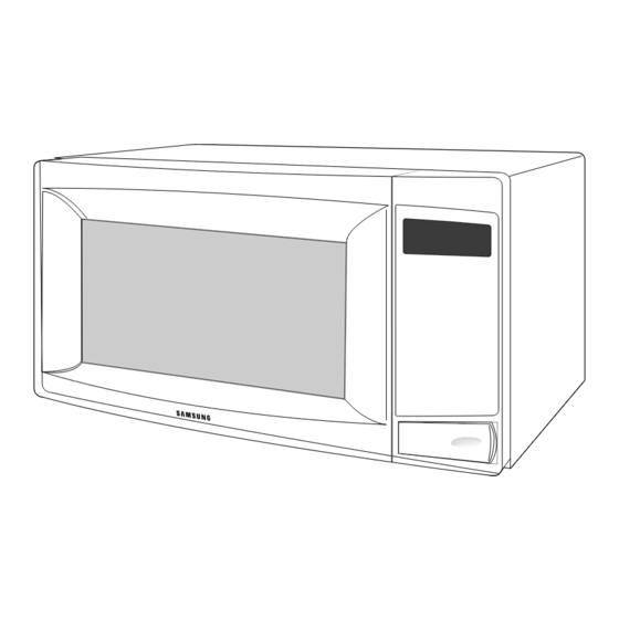
Page 5: Operating Instructions
Pause / Canel Cancel Press to pause oven or correct a mistake. 3-2 Features & External Views Safety Interlock Holes Light Ventilation Holes Door Control Panel Door Latches Open Door Push Button Guide Roller Glass Tray 601mm 468mm Samsung Electronics... -
Page 6: Disassembly And Reassembly
There exists HIGH VOLTAGE ELECTRICITY with high current capabilities in the circuits of the HIGH VOLTAGE TRANSFORMER secondary and filament terminals. It is extremely dangerous to work on or near these circuits with the oven energized. DO NOT measure the voltage in the high voltage circuit including filament voltage of magnetron. Samsung Electronics... -
Page 7: Replacement Of Door Assembly
• Insertion depth of the thin metal plate should be 0.5mm or less. 4-3-3 Removal of Key Door & Spring Door "E" Remove pin hinge from Door "E" Detach spring from Door "E" and key door. Key Door Spring Samsung Electronics... -
Page 8: Replacement Of Fuse/Drive Motor
7. When replacing the drive motor, be sure to remount it in the correct position with the Drive Motor Cover Base Plate coupler. 8. Connect all the leads to the drive motor. 9. Screw the drive motor cover to the base plate with a screw driver. Samsung Electronics... - Page 9 3. When installing new membrane key board, make sure that the surface of escutcheon base is cleaned sufficiently so that any problems (shorted contacts or uneven surface) can be avoided. Membrane Panel Samsung Electronics...
-
Page 10: Alignment And Adjustments
2. Isolate the magnetron from the circuit by disconnecting its leads. 3. A continuity check across the magnetron filament terminals should indicate one ohm or less. 4. A continuity check between each filament terminal and magnetron case should read open. Cooling Fins Samsung Electronics... -
Page 11: High Voltage Capacitor
Door Open Door Closed procedures. ∞ Primary switch 5. Confirm that the gap between the switch ∞ Monitor switch (COM-NC) housing and the switch actuator is no more than ∞ Door Sensing S/W 0.5mm when door is closed. Samsung Electronics... - Page 12 NOTE 1 : Variations or errors in the test procedure will cause a variance in the temperature rise. Additional power test should be made if temperature rise is marginal. NOTE 2 : Output power in watts is computed by multiplying the temperature rise (step 5) by a factor of 91 times the of centigrade temperature. Samsung Electronics...
-
Page 13: Procedure For Measurement Of Microwave Energy Leakage
; CENTRAL SERVICE CENTER 5-12-2 At least once a year have the microwave energy survey meter checked for accuracy by its manufacturer. Samsung Electronics... -
Page 14: Troubleshooting
H.V.Transformer component test procedure and replace if it is H.V.Capacitor defective. H.V.Diode Magnetron 4. Open or loose wiring of power relay 5. Defective primary latch switch 6. Defective power relay or Ass'y PCB Replace PCB main. Samsung Electronics... - Page 15 Use plastic wrap or cover with a lid. Stir once or twice while cooking foods such as soup, cocoa, or milk. Noise from the turntable motor Noise may result from the motor. Replace turntable motor. when it starts to operate. Samsung Electronics...
-
Page 16: Exploded Views And Parts List
7. Exploded Views and Parts List 7-1 Exploded Views Samsung Electronics... -
Page 17: Main Parts List
Specification Q'ty Remarks DE70-30033H PANEL-OUTER C/STEEL,T0.6,W464.1,L1259.4,WH 3601-000440 FUSE-FERRULE 250V,20A,TL,CERAMIC,6.35x31.8m DE96-00012A ASSY NOISE FILTER SN-3WUB,250V20A,3W 20A DE31-00001A MOTOR-FAN SMF-789UA,120V,60HZ,2550RPM,MW7592W DE39-00074A WIRE HARNESS-A 120V60HZ,-,-,MW8490W/XAC DE47-20030A THERMOSTAT PW-2N(160/60,Z,30),250V/7.5A,1 OM75PH(31)ESS ASSY-MAGNETRON OM75PH(31)ESS 4713-001102 LAMP-INCANDESCENT 125V,-,25W,TRP,-,-,25x62mm DE71-00012A COVER-AIR SGCC,T0.6,-,-,MW9596W DE96-00005A ASSY BODY LATCH MW7896W,3RD-W,WONWOO,PP(FB53WH),P/BUT DE66-90113A LEVER-DOOR PP(TB53-GH10),T2.5,W31X100.5,-,12G,NTR,3RD-W... -
Page 18: Door Parts List
ASSY PCB PARTS MW7490W,120V60Hz DE94-00210A ASSY CONTROL-PANEL MW8592W,PURE-WHT DE67-40179A WINDOW-DISPLAY SAN,T2.0,-,-,SMOG,-,3RD-W S1 7-5 Body Latch Parts List Ref. No. Parts No. Description Specification Q'ty Remarks DE66-40001C LATCH-BODY PP(FB53WH),-,39.2G,NTR,-,3RD-W MW5592W 3405-001034 SWITCH-MICRO 125/250VAC,16A,200GF,SPST-NO 3405-001032 SWITCH-MICRO 125/250VAC,16A,200GF,SPDT DE66-90114A LEVER-S/W PP(FB53WH),-,-,-,3.5G,NTR,3RD-W MW5592W,- Samsung Electronics... -
Page 19: Standard Parts List
C/BLWR DE60-10082I SCREW-A 2S-4X12,FEFZY CN/BOX DE60-10082I SCREW-A 2S-4X12,FEFZY MEM/PN DE60-10082I SCREW-A 2S-4X12,FEFZY N/FLTR DE60-10082I SCREW-A 2S-4X12,FEFZY P/CORD DE60-10082I SCREW-A 2S-4X12,FEFZY PN/OUT DE60-10082H SCREW-A 2S-4X12,TOOTHED C/MOTOR DE60-10082J SCREW-TAPPING TH,2S-4X8,MSWR3,ZPC,YEL,WS BKT/HVC DE60-10012A SCREW-TAP TITE TH,+,3,M4,L10,SWR10,ZPC2,TOOTH DE60-10088A SCREW-TAP PH PH,M3,L8,FEFZY,PLAIN CON-BOX Samsung Electronics... - Page 20 8. P.C.B Diagrams 8-1 P.C.B Diagrams Samsung Electronics...
- Page 21 4MHz,0.5%,TP,10.0x5.0x7.5mm XTL1 P34 3711-000940 CONNECTOR-HEADER BOX,4P,1R,2.5mm,STRAIGHT,SN CN03 P35 3711-004143 CONNECTOR-HEADER BOX,2P/3P,1R,5mm/2.5mm,STRAIGH CN07 P36 DE13-20009A KA7533,DIP IC02 P37 DE39-60001A WIRE-SO COPPER PI0.6,SN,T,52MM,TAPING_WIRE J01,J02,J04,J05,J10 P37 DE39-60001A WIRE-SO COPPER PI0.6,SN,T,52MM,TAPING_WIRE J11,J12,J13,J14,J15 P37 DE39-60001A WIRE-SO COPPER PI0.6,SN,T,52MM,TAPING_WIRE P38 DE09-00032A IC-MCU HCD6433724-F18,MW5693W(3RD-VFD),8BIT IC01 Samsung Electronics...
-
Page 22: Schematic Diagrams
AC 120V/60Hz POWER RELAY (SECONDARY INTERLOCK) MAGNETRON BLK PNK HIGH VOLTAGE DIODE TO CHASSIS PRIMARY SWITCH HIGH VOLTAGE CAPACITOR DOOR SENSING SWITCH MONITOR SWITCH BOTTOM CENTER SYMBOL COLOR ORANGE HIGH VOLTAGE WHITE TRANSFORMER BLACK BLUE WHT WHT POWER RELAY Samsung Electronics...
Need help?
Do you have a question about the mw8490w and is the answer not in the manual?
Questions and answers