Table of Contents
Advertisement
Quick Links
nAtUrAL
GAS MODeLS GAS MODeLS
DvF-36nS-S
DvF-36nh-S
DvF-42nS-S
DvF-42nh-S
hiGh ALtitUDe
nAtUrAL GAS MODeLS
DvF-36AnS-S
DvF-36Anh-S
DvF-42AnS-S
DvF-42Anh-S
WARNING: If the information in this manual is not
followed exactly, a fire or explosion may result causing
property damage, personal injury or loss of life.
— Do not store or use gasoline or other flammable
vapors and liquids in the vicinity of this or any other
appliance.
— WHAT TO DO IF YOU SMELL GAS
• Do not try to light any appliance.
• Do not touch any electrical switch; do not use any
phone in your building.
• Immediately call your gas supplier from a neighbor's
phone. Follow the gas supplier's instructions.
• If you cannot reach your gas supplier, call the fire
department.
— Installation and service must be performed by a quali-
fied installer, service agency or the gas supplier.
INSTALLER: Leave this manual with the appliance
CONSUMER: Retain this manual for future reference.
Direct vent FirePLAce
OWner'S OPerAtiOn AnD
inStALLAtiOn MAnUAL
PrOPAne/LP
DvF-36PS-S
DvF-36Ph-S
DvF-42PS-S
DvF-42Ph-S
Stacked Brick
herringbone Brick
Stacked Brick
herringbone Brick
For more information, visit www.desatech.com
Stacked Brick
herringbone Brick
Stacked Brick
herringbone Brick
Advertisement
Table of Contents

Related Manuals for Design Dynamics DVF-36NS-S

Summary of Contents for Design Dynamics DVF-36NS-S
- Page 1 Direct vent FirePLAce OWner’S OPerAtiOn AnD inStALLAtiOn MAnUAL nAtUrAL PrOPAne/LP GAS MODeLS GAS MODeLS DvF-36nS-S DvF-36PS-S Stacked Brick DvF-36nh-S DvF-36Ph-S herringbone Brick DvF-42nS-S DvF-42PS-S Stacked Brick DvF-42nh-S DvF-42Ph-S herringbone Brick hiGh ALtitUDe nAtUrAL GAS MODeLS DvF-36AnS-S Stacked Brick DvF-36Anh-S herringbone Brick...
-
Page 2: Table Of Contents
tABLe OF cOntentS Safety ..............2 Inspecting Burners..........24 Local Codes............4 Cleaning and Maintenance ........ 24 Product Identification ........... 5 Troubleshooting ..........26 Product Features ..........5 Specifications ............ 29 Pre-installation ............. 6 Wiring Diagram ..........29 Location of Termination Cap ........ 8 Parts .............. - Page 3 SAFety Continued Carbon Monoxide Poisoning: Early signs WARNING: Do not allow fans of carbon monoxide poisoning resemble the flu, with headaches, dizziness or nausea. If to blow directly into the fireplace. you have these signs, the fireplace may not Avoid any drafts that alter burner be working properly.
-
Page 4: Local Codes
SAFety Continued 1. For propane/LP fireplace, do not place 6. Have venting system inspected annually by propane/LP supply tank(s) inside any a qualified service person. If needed, have structure. Locate propane/LP supply venting system cleaned or repaired. See tank(s) outdoors. To prevent performance Cleaning and Maintenance, page 24. -
Page 5: Product Identification
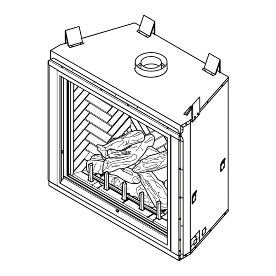
PrODUct iDentiFicAtiOn Flue Collar Outer Glass Door Herringbone Brick Refractories Nailing Flange Log Set Grate Lower Door/ Control Cover Figure 1 - Direct Vent Fireplace PrODUct FeAtUreS These are a few facts that can help you under- • Each time you turn on your fireplace, you stand and enjoy your direct vent fireplace: may notice some amount of condensation on the inside of the fireplace glass. -
Page 6: Pre-Installation
Pre-inStALLAtiOn LOCATION AND SpACE • You may paint the termination cap with REqUIREMENTS 450º F (232º C) heat-resistant paint to coordinate with the exterior finish. Determine the safest and most efficient loca- tion for your direct vent fireplace. Make sure •... - Page 7 Pre-inStALLAtiOn Continued CLEARANCES Minimum clearances to combustibles for the fireplace are as follows: *Back and sides 1" Perpendicular walls 6" Floor 0" Ceiling to louver opening 42" Front 36" Top of Standoffs 0" Vent (See venting instructions for specific venting clearances.) Combustible material with a maximum thick- "...
-
Page 8: Location Of Termination Cap
LOcAtiOn OF terMinAtiOn cAP Fixed Openable Fixed Closed Closed Openable TERMINATION CAP GAS METER RESTRICTED AREA AIR SUPPLY INLET (TERMINATION PROHIBITED) A = clearance above grade, veranda, porch, deck, or I = clearance to service regulator vent outlet [*72" (182.9 cm) balcony [*12"... -
Page 9: Requirements For The Commonwealth Of Massachusetts
reqUireMentS FOr the cOMMOnWeALth OF MASSAchUSettS For all side wall horizontally vented gas fueled INSpECTION equipment installed in every dwelling, building or The state or local gas inspector of the side structure used in whole or in part for residential wall horizontally vented gas fueled equipment purposes, including those owned or operated by shall not approve the installation unless, upon... -
Page 10: Venting Installation
ventinG inStALLAtiOn NOTICE: Read these instruc- NOTICE: Do not seal termination tions completely before attempt- cap to vent pipe. Cap must be removable for vent inspection ing installation. and maintenance. These models are tested and approved for use with DESA Heating, LLC (direct vent) pipe INSTALLATION pRECAUTIONS components and terminations. -
Page 11: Venting Installation
ventinG inStALLAtiOn Continued INSTALLATION pLANNING etrated is constructed of noncombustible material, such as masonry block or con- There are two basic types of direct vent crete, a 8 " hole with zero clearance is installation: acceptable (see Figure 9). • Horizontal Termination •... - Page 12 ventinG inStALLAtiOn Continued Carefully move fireplace, with vent as- 5. Noncombustible Exterior Wall: Position sembly attached, toward wall and insert horizontal vent cap in center of the 8 " vent pipe into horizontal termination. Pipe round hole and attach to exterior wall overlap should be a minimum of 1 "...
- Page 13 ventinG inStALLAtiOn Continued GROUND FLOOR INSTALLATION Minimum Siding Recommended Applications: Pipe Standoff Overlap • Through the wall using round or square Direct Screws termination Vent Pipe • NOT FOR CORNER INSTALLATION Wall 1' Pipe Min On Firestop 90° Elbow Horizontal Run Wall Firestop V + 90·...
- Page 14 ventinG inStALLAtiOn Continued 2. Set fireplace in desired location. Drop a 2. Assemble desired lengths of pipe and plumb line down from ceiling to position elbows necessary to reach from fireplace of fireplace exit flue. Mark center point flue up through firestop. Be sure all pipe where vent will penetrate ceiling.
-
Page 15: High Altitude Installation
ventinG inStALLAtiOn Continued If area above is an attic or insulated area, HIGH ALTITUDE INSTALLATION install firestop above framed hole. Your DESA Heating, LLC direct vent fireplace has been tested and approved for elevations from 0-2000 feet. Fireplaces for high altitude (DVF-36AN(H,S)-S and DVF-42AN(H,S)-S) are for installations above 4,000 feet only. -
Page 16: Fireplace Installation
FirePLAce inStALLAtiOn CHECK GAS TYPE For propane/LP connection only, the installer Use proper gas type for the fireplace unit you must supply an external regulator. The exter- are installing. If you have conflicting gas types, nal regulator will reduce incoming gas pres- do not install fireplace. - Page 17 FirePLAce inStALLAtiOn Continued Check your building codes for any special WARNING: Use pipe joint requirements for locating equipment shutoff valve to fireplaces. sealant that is resistant to liquid Apply pipe joint sealant lightly to male NPT petroleum (LP) gas. threads. This will prevent excess sealant from going into pipe.
- Page 18 FirePLAce inStALLAtiOn Continued CHECKING GAS CONNECTIONS 3. Check all joints from propane/LP supply tank or gas meter to equipment shutoff WARNING: Test all gas piping valve (see Figure 22 or Figure 23). Apply noncorrosive leak detection fluid to all and connections, internal and joints.
- Page 19 FirePLAce inStALLAtiOn Continued 3. Make sure control knob of fireplace is in Removing Glass Door the OFF position. If replacement of glass is necessary, the entire frame assembly must be replaced. Gloves 4. Check all joints from equipment shutoff must be worn when removing/replacing glass valve to gas valve (see Figure 22 or door.
- Page 20 FirePLAce inStALLAtiOn Continued LAVA ROCK, DECORATIVE GRATE, Lava Rock EMBER FLAKES AND SCRAP LOG INSTALLATION Lava rock, ember flakes and scrap log pieces are included with your fireplace. Install these items while glass doors are open and/or removed. 1. Follow instructions from Removing/Re- placing Glass Door, page 19, to move glass out of the way of this installation.
- Page 21 FirePLAce inStALLAtiOn Continued WARNING: Never use an Assembly Burner Base open flame to check for a leak. Apply noncorrosive leak de- tection fluid to joints. Bubbles forming show a leak. Correct leaks at once. CAUTION: The gas supply Spacers shall be shut off prior to discon- Firebox necting the electrical power, if Bottom...
-
Page 22: Operation
FirePLAce inStALLAtiOn Continued Installing Batteries in Hand-Held Remote 2. Install 3 AAA batteries as instructed in Control Unit battery housing. 1. Remove battery cover on back of remote 3. Replace battery cover onto remote control unit. control unit. Battery Cover Remote Control Unit... - Page 23 OPerAtiOn Continued 5. Turn equipment shutoff valve clockwise TO TURN OFF GAS to the OFF position (see Figure TO AppLIANCE 33). Do not force. 1. Turn off safety shutoff switch. 6. Wait five (5) minutes to clear out any gas. 2.
-
Page 24: Inspecting Burners
inSPectinG BUrnerS BURNER FLAME pATTERN Check pilot flame pattern and burner flame patterns often. Burner flames will be steady, not lifting or float- ing. Flame patterns will be different from unit pILOT ASSEMBLY to unit and will vary depending on installation The pilot assembly is factory preset for the type and weather conditions. - Page 25 cLeAninG AnD MAintenAnce Continued Glass must be cleaned periodically. During WARNING: Do not operate start-up it is normal for condensation to form on the inside of the glass causing lint, dust and fireplace with glass door un- other airborne particles to cling to the glass latched, removed, cracked or surface.
-
Page 26: Troubleshooting
trOUBLeShOOtinG WARNING: Turn off fireplace and let cool before servicing. Only a qualified service person should service and repair fireplace. CAUTION: Never use a wire, needle or similar object to clean pilot. This can damage pilot unit. Note: All troubleshooting items are listed in order of operation. OBSERVED PROBLEM pOSSIBLE CAUSE REMEDY... - Page 27 trOUBLeShOOtinG Continued OBSERVED PROBLEM pOSSIBLE CAUSE REMEDY Pilot will not stay lit 1. Loose wiring on ignitor wire 1. Check wiring connection. to ignition module and/ Refer to wiring diagram or poor ground to ignition (see Wiring Diagram, page module 29) and/or check ground wire to ignition module 2.
- Page 28 trOUBLeShOOtinG Continued WARNING: If you smell gas • Shut off gas supply. • Do not try to light any appliance. • Do not touch any electrical switch; do not use any phone in your building. • Immediately call your gas supplier from a neighbor’s phone. Fol- low the gas supplier’s instructions.
-
Page 29: Specifications
SPeciFicAtiOnS DVF-36N(S,H)-S DVF-42P(S,H)-S • Rating: 33,500 Btu/hr • Rating: 37,000 Btu/hr • Gas Type: Natural Gas Only • Gas Type: Propane/LP Gas Only • Ignition: Electronic • Ignition: Electronic • Manifold Pressure: 3.5" w.c. • Manifold Pressure: 10.0" w.c. • Minimum Inlet Supply Pressure: 5" w.c. •... -
Page 30: Parts
PArtS MODELS DVF-36(A)NS-S, DVF-36(A)NH-S, DVF-42(A)NS-S, DVF-42(A)NH-S, DVF-36PS-S, DVF-36PH-S, DVF-42PS-S, DVF-42PH-S 33(36") 32(42") www.desatech.com 123163-01C... - Page 31 PArtS This list contains replaceable parts used in your fireplace. When ordering parts, follow the instructions listed under Replacement Parts on page 35 of this manual. PART NO. DESCRIpTION 122653-01 Door Assembly, 36" • • • 122653-02 Door Assembly, 42" •...
- Page 32 PArtS BURNER ASSEMBLY MODELS DVF-36(A)NS-S, DVF-36(A)NH-S, DVF-42(A)NS-S, DVF-42NH-S, DVF-36PS-S, DVF-36PH-S, DVF-42PS-S, DVF-42PH-S www.desatech.com 123163-01C...
-
Page 33: Burner Assembly
PArtS BURNER ASSEMBLY This list contains replaceable parts used in your fireplace. When ordering parts, follow the instructions listed under Replacement Parts on page 35 of this manual. NO. PART NO. DESCRIpTION QTY. 122839-02 Burner Tube, 36" • • • 122839-01 Burner Tube, 42"... - Page 34 PArtS REFRACTORY pARTS Herringbone Brick Shown NO. PART NO. DESCRIpTION 123137-01 Rear Refractory, Herringbone 42" • • 123234-01 Rear Refractory, Herringbone 36" • • 123141-01 Rear Refractory, Stacked 42" • • 123235-01 Rear Refractory, Stacked 36" • • 123136-01 Left Refractory, Herringbone 42" •...
-
Page 35: Replacement Parts
rePLAceMent PArtS Usually, we will ask you to return the part to Note: Use only original replacement parts. the factory. This will protect your warranty coverage for parts replaced under warranty. pARTS NOT UNDER WARRANTY pARTS UNDER WARRANTY Contact authorized dealers of this product. If they can’t supply original replacement part(s), Contact authorized dealers of this product. -
Page 36: Warranty
WArrAnty KeeP thiS WArrAnty Model (located on product or identification tag) _____________________________ Serial No. (located on product or identification tag) __________________________ Date Purchased __________________________ Keep receipt for warranty verification. DeSA heAtinG, LLc LiMiteD WArrAntieS New products Standard Warranty: DESA Heating, LLC warrants this new product and any parts thereof to be free from defects in material and workmanship for a period of two (2) years from the date of first purchase from an authorized dealer provided the product has been installed, maintained and operated in accordance with DESA Heating, LLC’s warnings and instructions.
Need help?
Do you have a question about the DVF-36NS-S and is the answer not in the manual?
Questions and answers