Table of Contents
Advertisement
Quick Links
PC/104-Plus SBC with Intel E3800 "Bay Trail" Processor
Revision
A.00
A.01
A.02
FOR TECHNICAL SUPPORT
PLEASE CONTACT:
support@diamondsystems.com
Aries User Manual Rev A.02
Aries Single Board Computer
Date
3/26/2015
Initial Release
8/26/2015
JP4 update and minor changes
11/3/2015
Section 8.5 removed
www.diamondsystems.com
Comment
Diamond Systems Corporation
Mountain View, CA 94043 USA
www.diamondsystems.com
Copyright 2015
555 Ellis Street
Tel 1-650-810-2500
Fax 1-650-810-2525
Page 1
Advertisement
Table of Contents

Related Manuals for Diamond Aries PC/104-Plus SBC

Summary of Contents for Diamond Aries PC/104-Plus SBC
- Page 1 Initial Release A.01 8/26/2015 JP4 update and minor changes A.02 11/3/2015 Section 8.5 removed Copyright 2015 FOR TECHNICAL SUPPORT Diamond Systems Corporation PLEASE CONTACT: 555 Ellis Street Mountain View, CA 94043 USA support@diamondsystems.com Tel 1-650-810-2500 Fax 1-650-810-2525 www.diamondsystems.com www.diamondsystems.com Aries User Manual Rev A.02...
-
Page 2: Table Of Contents
CONTENTS Important Safe Handling Information ......................4 Introduction ...............................6 Models ................................6 Features .................................6 Operating System Support ..........................7 Mechanical, Electrical, Environmental ......................7 Functional Overview ............................8 Block Diagram ...............................8 Feature Descriptions .............................9 3.2.1 Processor and Memory .........................9 3.2.2 Ethernet..............................9 3.2.3 Video ..............................9 3.2.4 SATA ..............................9 3.2.5 USB ...............................9... - Page 3 Quiet / Quick Boot / Splash Screen ......................32 Selecting the Displays ..........................33 Serial Port Configuration ..........................33 Getting Started ............................... 33 Development Kit ............................33 Quick Setup ..............................34 Boot Device Options ........................... 34 10. Data Acquisition Circuit ..........................35 10.1 Overview ..............................
-
Page 4: Important Safe Handling Information
The list here describes common causes of failure found on boards returned to Diamond Systems for repair. This information is provided as a source of advice to help you prevent damaging your Diamond (or any vendor’s) embedded computer boards. - Page 5 Overvoltage on analog input – If a voltage applied to an analog input exceeds the design specification of the board, the input multiplexor and/or parts behind it can be damaged. Most of our boards will withstand an erroneous connection of up to 35V on the analog inputs, even when the board is powered off, but not all boards, and not in all conditions.
-
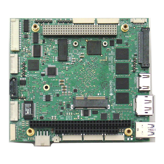
Page 6: Introduction
2. INTRODUCTION Aries is an embedded single board computer (SBC) in the PC/104 form factor. Aries integrates on-board memory, PC/104-Plus expansion, one PCIe Mini card socket, dual Gigabit Ethernet and optional data acquisition circuit with analog and digital I/O. The Aries SBC is based on Intel “Bay Trail” E3800 series processors. The form factor is similar to PC/104 with left and right side extensions that extend the full length of the two sides without providing the corners traditionally seen in PC/104 boards with “wings”. -
Page 7: Operating System Support
2.3 Operating System Support Windows 7, 8, Linux Driver packages and/or BSPs available for each OS 2.4 Mechanical, Electrical, Environmental PC/104 form factor 4.5” x 4.0” (not including I/O connector overhang). -40°C to +85°C ambient operating temperature Power input: +5VDC +/- 5% www.diamondsystems.com Aries User Manual Rev A.02 Page 7... -
Page 8: Functional Overview
3. FUNCTIONAL OVERVIEW 3.1 Block Diagram Figure 1: Functional Block Diagram www.diamondsystems.com Aries User Manual Rev A.02 Page 8... -
Page 9: Feature Descriptions
3.2 Feature Descriptions This section describes the key subsystems of the Aries SBC. 3.2.1 Processor and Memory Aries core embedded computer circuit is based on Intel’s Bay Trail. Depending on the model chosen the processors speed and its memory will differ. The two different cores available are 1.91GHz quad core Intel E3845 with 4GB DDR3 and 1.46GHz dual core Intel E3826 with 2GB DDR3 memory. -
Page 10: Data Acquisition
3.2.8 Data Acquisition Aries provides an optional data acquisition sub-circuit containing analog input, analog output, and digital I/O features. This circuit is controlled by an FPGA attached to the processor via the LPC bus. A pin header on the board provides access to JTAG signals for reprogramming the FPGA on the board and in the field. Type of I/O Characteristics 16 single-ended/8 differential inputs, 16-bit resolution... -
Page 11: Led Indicators
Customizable splash screen Quiet boot option POST message will display “Diamond Systems Corporation” and also display the board name and BIOS version. The BIOS version will be displayed as “Major.Minor-rev – Date Built” format. For example “Version 1.01 – 12-Oct-2012”. - Page 12 3.2.15.1 POWER SUPPLY The board requires only +5VDC input voltage as per the PC/104 Specification. It supports ACPI pushbutton on/off control. It supports Standby mode. In standby mode the board may be powered on via Wake on LAN feature on at least one Ethernet port.
-
Page 13: Mechanical Board Drawing
4. MECHANICAL BOARD DRAWING Figure 2: Mechanical Board Drawing www.diamondsystems.com Aries User Manual Rev A.02 Page 13... -
Page 14: Board Layout
5. BOARD LAYOUT Block 4 Block 2 Block 1 Block 3 Figure 3: Board Layout www.diamondsystems.com Aries User Manual Rev A.02 Page 14... -
Page 15: I/O Connectors, Jumpers And Led Summary
5.1 I/O Connectors, Jumpers and LED Summary Connector Function Jumper Function PC/104 - ISA A/B LVDS VCC & Backlight PC/104 - ISA C/D SATA DOM PC/104-Plus - PCI Digital VIO Miscellaneous HDMI LED Block 1 LED (Leftmost BIOS in the block) USB-3.0 LED (Middle PWRON... -
Page 16: I/O Connectors
6. I/O CONNECTORS 6.1 Connector Pin-out and Signal Description 6.1.1 PC/104 (J1, J2) The Aries SBC contains the non-stack-through / short pin 8-bit and 16-bit PC/104 connectors on the top side in the standard position as described by the PC/104-Plus specification. Press fit PC/104 connectors have been used. -
Page 17: Pc-104 (J3)
6.1.2 PC-104 (J3) The board contains a non-stack through / short pin PC-104 connector on the top side in the standard position as described by the PC/104-Plus specification. GND/5.0V KEY Reserved AD00 VI/O AD02 AD01 AD05 AD04 AD03 C/BE0* AD07 AD06 AD09 AD08... -
Page 18: Lvds Lcd (J4)
6.1.3 LVDS LCD (J4) J4 can be used to connect the LCD. Connector J4 provides access to the internal LVDS LCD display drivers. Note that the connector J20 can be used for LCD backlight properties. The LCD panel power is jumper-selectable for 3.3V (default) or 5V. -
Page 19: Hdmi (J5)
6.1.4 HDMI (J5) Standard HDMI connector Type A right angle has been mounted on the board. Note: If HDMI is used, Display Port will not be available and vice versa. Selection between HDMI and DP can be done from BIOS GUI. Data 2+ Ground Data 2-... -
Page 20: Usb 3.0 Ports (J7)
6.1.6 USB 3.0 Ports (J7) Connector J7 provides both USB 3.0 and USB 2.0 connections. USB Power USB 2.0 Data- USB 2.0 signals USB 2.0 Data+ Ground SSRX- SSRX+ Ground USB 3.0 signals SSTX- SSTX+ Connector Type: USB 3.0 type A receptacle, right angle 6.1.7 USB 2.0 Ports (J8) Aries provides four USB 2.0 ports. -
Page 21: Serial Ports (J9, J10)
6.1.8 Serial ports (J9, J10) Connector J9 and J10 provide 4 serial ports for RS-232/422/485 protocols, two ports per connector. Pin-out of both connectors is the same. The following tables list the signal assignments on the pin header for each serial protocol. DB15 pin equivalent RS-232 RS-422... -
Page 22: Audio (J13)
6.1.11 Audio (J13) Audio signals are made available on a latching connector J13. LineOut – L LineOut – R GND_Audio LineIn – L LineIn – R GND_Audio MIC IN GND_Audio Connector Type: 8 position 1.25mm pitch right angle latching 6.1.12 Ethernet (J14) Ethernet ports 1 and 2 are made available on the header J14 connected by two magnetics one per port. -
Page 23: Digital I/O (J16)
6.1.14 Digital I/O (J16) Aries provides three digital I/O ports with 8 lines on port A and B, and 6 lines on port C. Port A and B are provided on connector J16. Port C is on connector J17 and pin 18 of connector J16. VIO (fused) DIO A0 DIO A1... -
Page 24: Utility Connector (J18)
6.1.16 Utility Connector (J18) Status LED’s of Ethernet ports are accessible from the utility connector J18. The 3.3V pin is connected to the system 3.3V rail through a poly-switch resettable fuse. I2C Clock I2C Data Ground Reset Power Switch Eth 1 Activity Eth 1 Link 100 Eth 1 Link 1000 Eth 2 Activity... -
Page 25: Vga (J19)
6.1.17 VGA (J19) Connector J19 is used for connecting a VGA monitor. Signal DB15 pin equivalent Gnd-Red Green Gnd-Green Blue Gnd-Blue HSync VSync Gnd-Sync DDC-Data DDC-Clock Ground Signal Definition Ground Ground return RED signal Green GREEN signal Blue BLUE signal DDC clock/data Digital serial I/O signals used for monitor detection (DDC1 specification) HSYNC... -
Page 26: Msata / Pcie Minicard Socket (J21)
6.1.19 mSATA / PCIe MiniCard Socket (J21) This socket can be used for both PCIe MiniCard and mSATA disk module use. The configuration is selected with a switch that is controlled by pin 7. A PCIe MiniCard will tie pin 7 to ground, while an mSATA module will leave pin 7 open. -
Page 27: List Of Connectors
6.2 List of Connectors The following table provides a summary of all I/O connectors on the board and their corresponding Diamond Systems cables where appropriate. Connectors on the top side are mostly vertical, and connectors on the bottom side are always right-angle... -
Page 28: Jumper Description
7. JUMPER DESCRIPTION Following drawing shows only the connectors and jumper blocks on the board. The default jumpers of the jumper blocks are shown in red. Figure 4: Default Jumper locations Jumper Description LVDS VDD & Backlight SATA DOM Digital VIO PCI voltage selection and FPGA base address www.diamondsystems.com Aries User Manual Rev A.02... -
Page 29: Lvds Backlight And Lvds Vdd (Jp1)
7.1 LVDS Backlight and LVDS VDD (JP1) Jumper block JP1 configures the voltage supply for the LCD backlight and for LVDS VDD as well. The orientation of the block in the diagrams matches the orientation of the jumper block when the board is rotated so that the PC/104 connector is on the lower edge. -
Page 30: Digital Io (Jp3)
Description SATA_PIN7 = GND (SATA CABLE) SATA_PIN7 = 5.0V (SATA DOM) 7.3 Digital IO (JP3) The digital I/O can be pulled up to 5V/3.3V or pulled down to GND by configuring jumper block JP3. The jumper locations of this jumper block will also determine the input voltage to the DAQ circuit. By default the DIO’s are pulled high to 3.3V. -
Page 31: Miscellaneous (Jp4)
7.4 Miscellaneous (JP4) Jumper block JP4 can be used to select the PCI voltage and configure the FPGA base address. The following information describes how to set these various options. PCI Voltage Selection The PCI voltage can be set for either 3.3V or 5V with pins 1, 2 and 3 of JP4 as follows: Jumper on Pins PCI voltage 1 &... -
Page 32: Bios Key Features
(if available). Quick boot turns off memory test during startup to save time. To enable these features, go to the Boot menu, then select Boot Settings Configuration. Diamond can provide custom splash screens upon request from an image file. -
Page 33: Selecting The Displays
8.7 Selecting the Displays Aries SBC supports two independent displays at a given time. Any two of the following displays can be selected from BIOS GUI: LVDS DP or HDMI 8.8 Serial Port Configuration Aries SBC provides four serial ports. Each of these ports can be individually configured as RS-232/422/485 from the BIOS GUI. -
Page 34: Quick Setup
9.2 Quick Setup 1. Attach VGA cable 6980507, USB keyboard / mouse cable and USB cables 6980503 as needed. 2. Attach display, keyboard, and mouse (if needed) to the cables. 3. Connect the jumpers as mentioned in Section 7 for a default settings or can be changed as desired by the user. -
Page 35: Data Acquisition Circuit
10. DATA ACQUISITION CIRCUIT 10.1 Overview Aries contains a Data Acquisition subsystem consisting of A/D, D/A, digital I/O, and counter/timer features. The A/D section includes a 16-bit A/D converter, 16 analog input channels and a 2048-sample FIFO. Input ranges are programmable, and the maximum sampling rate is 250 KHz. The D/A section include 4 16-bit D/A channels. The digital I/O section includes up to 22 lines with programmable direction. -
Page 36: Fpga
10.2 FPGA FPGA provides all logic functions of the Aries baseboard data acquisition as well as a watchdog timer and a power sequencing circuit. The chip also interfaces to a Renesas encryption chip for future security features. The following table shows a list of all the features offered by Aries FPGA. Feature Description A/D channels... - Page 37 ADINT=1 and an interrupt occurs when ADINTEN=1 and one of the following occurs: FIFOEN SCANEN Action Interrupt occurs after each A/D conversion completes (ADBUSY goes low). Interrupt occurs after each A/D scan completes (ADBUSY goes low). Interrupt occurs when A/D conversion completes and FIFO threshold is reached or exceeded.
-
Page 38: A/D Circuit
11. A/D CIRCUIT 11.1 A/D Input Ranges and Resolution Aries uses a 16-bit A/D converter. This means that the analog input voltage can be measured to the precision of a 16-bit binary number. The maximum value of a 16-bit binary number is 216 - 1, so the full range of numerical values that user can get from Aries input channel is 0 - 65535. -
Page 39: Conversion Formulas
11.3.1 Conversion Formulas The 16-bit value returned by the A/D converter is always a two’s complement number ranging from -32768 to 32767, regardless of the input range. This is because the input range of the A/D is fixed at ±10V. The input signal is actually magnified and shifted to match this range before it reaches the A/D. -
Page 40: A/D Sampling Methods
11.3.1.2 CONVERSION FORMULA FOR UNIPOLAR INPUT RANGES Input voltage = (A/D code + 32768) / 65536 * Full-scale input range Example: Given, Input range is 0–10V and A/D code is 17761. Therefore, Input voltage = (17761 + 32768) / 65536 * 10V = 7.7103V. For a unipolar input range, 1 LSB = 1/65536 * Full-scale voltage. -
Page 41: Scan Sampling
Note: If both scan and FIFO operations are enabled, the interrupt occurs at the programmed FIFO threshold and the interrupt routine reads the indicated number or samples and then exits. This happens even if the number of samples is not an integral number of scans. For example, if the user has a scan size of 10 and a FIFO threshold of 256, the first time the interrupt routine runs, it reads 256 samples, consisting of 25 full scans of all 10 channels followed by 6 samples from the next scan. -
Page 42: D/A Circuit
Interrupt Used for controlled-rate sampling of single channels or Single multiple channels in round-robin fashion, where the Conversion, frequency of sampling must be precise but is relatively slow Low Speed (<100Hz). The sampling clock comes from the on-board counter/timer or from an external signal. The interval between all A/D samples is identical. -
Page 43: Resolution
DAC supports is 0 - 65535. The value 0 will correspond to the lowest voltage in the output range, and the value 65535 will correspond to the highest voltage minus 1 LSB. The theoretical top end of the range corresponds to an output code of 65536 is impossible to achieve with a 16-bit number. -
Page 44: D/A Conversion Formulas For Bipolar Output Ranges
16-Bit Output Voltage Output Voltage for D/A Code Symbolic Formula 0-10V Range 0.0000V / 35536) 0.00024V 17767 / 2 - 1 LSB 4.9976V 17768 5.0000V 17769 / 2 + 1 LSB 5.0024V 35536 - 1 LSB 9.9976V 12.2.2 D/A Conversion Formulas for Bipolar Output Ranges In Bipolar output ranges, the D/A voltage will range from (–... -
Page 45: Calibration
All analog outputs power up to 0V for safety. If recalibration or calibration for nonstandard D/A ranges are needed, please contact Diamond Systems for technical support. All analog components contain inherent errors in offset and gain which affect the accuracy of the signals they generate. -
Page 46: Digital I/O
13. DIGITAL I/O The FPGA has three digital I/O ports named A, B, and C. The DIO is organized as follows in the FPGA: Port A = 8 bits with 1 bit for direction control of the entire port (DIRA) Port B = 8 bits with 8 bits for direction control (DIRB[7:0]) Port C = 6 bits with 6 bits for direction control (DIRC[5:0]) A 0 means input mode and a 1 means output mode. -
Page 47: Counters And Timers
14. COUNTERS AND TIMERS The FPGA contains 8 32-bit up/down counter timers with programmable functions. The counters are programmed using a command register at address 5 in the counter block, a counter number register at address 4, and a 32-bit data register CTRD31-0 at addresses 0-3. -
Page 48: Pulse Width Modulation
15. PULSE WIDTH MODULATION Aries supports 4 24-bit PWM circuits. The PWMs are programmed using a 24-bit PWM data register PWMD23-0 and an 8-bit command register PWCMD3-0 + PWM2-0 + PWMCD. Each PWM consists of a pair of 24-bit down counters named C0 and C1. The C1 counter defines the duty cycle (active portion of the signal), and the C0 counter defines the period of the signal. -
Page 49: Watchdog Timer
16. WATCHDOG TIMER The watchdog timer can be used to trigger an interrupt or system reset upon the expiration of a programmed time interval. The purpose of this timer is to enable the system to recover from a software or hardware error that causes the system to freeze or get caught up in a software infinite loop. -
Page 50: Thermal Solutions
17. THERMAL SOLUTIONS Aries SBCs come with a heat spreader which is mounted on the bottom side of the board The mechanical drawing of the heat spreader and the drawing for the heat spreader installed on the board are shown below. 17.1 Heat Spreader Drawing Figure 10: Mechanical Drawing of the Heat Spreader (Top View) www.diamondsystems.com... -
Page 51: Bottom View Of Heat Spreader
17.2 Bottom view of Heat Spreader Figure 11 shows the bottom view of the heat spreader pointing out all the positions of the components heat spreader would cover. Figure 11: Bottom view of the Heat Spreader www.diamondsystems.com Aries User Manual Rev A.02 Page 51... -
Page 52: Heat Spreader Installed On The Board
Figure 12: Detailed Measurements 17.3 Heat Spreader Installed on the Board Figure 13 shows the side view of the heat spreader installed on the Board. Figure 13: Heat Spreader installed on the board. www.diamondsystems.com Aries User Manual Rev A.02 Page 52... -
Page 53: Thermal Pad
17.4 Thermal Pad A thermal pad is also included that is the same size as the heat spreader and attaches to the bottom of the heat spreader, but is shipped loose with the product. Users can choose to affix the thermal pad or not depending on their needs. -
Page 54: Heat Sink Accessory
17.5 Heat Sink Accessory Aries also offers an add-on heat sink as an optional accessory, part number ACC-HS104-12.7. The heat sink attaches to the heat spreader forming a more traditional thermal solution for the SBC. Figure 15 shows the dimensions of the heat sink. Figure 15: Heat Sink (Bottom View) Aries SBC with heat sink attached Figure 16: Dimensions of the Heat sink when viewed form Bottom and Side View... -
Page 55: Specifications
18. SPECIFICATIONS Item ARS3845-4GA ARS3845-4GN ARS3826-2GA ARS3826-2GN CPU Circuit Processor Intel E3845 Intel E3845 Intel E3826 Intel E3826 Speed 1.91GHz 1.91GHz 1.46GHz 1.46GHz Cooling Heat Spreader Heat Spreader Heat Spreader Heat Spreader Optional Heat Sink Optional Heat Sink Optional Heat Sink Optional Heat Sink System bus 100MHz... -
Page 56: Data Acquisition Section
Data Acquisition Section Analog Inputs Number input channels 16 single-ended or 8 differential voltage inputs (software selectable) Resolution 16 bits (1/65,536 of full scale) Input ranges Bipolar: ±10V, ±5V, ±2.5V, ±1.25V Unipolar: 0-10V, 0-5V, 0-2.5V, 0-1.25V Maximum input voltage +6.5V for linear operation Over-voltage protection ±35V on any input without damage A/D conversion rate... -
Page 57: Appendix
19. APPENDIX I/O Space and IRQs under Windows 7 / 8 The following tables show the free I/O space and IRQs for the Aries SBC using the Windows 7 and 8 operating systems. Windows 7 Windows 8 IRQ Non- I/O Space I/O Space IRQ Non- I/O Space...
Need help?
Do you have a question about the Aries PC/104-Plus SBC and is the answer not in the manual?
Questions and answers