Table of Contents
Advertisement
Welcome!
Thank you for purchasing our SET-02. We would like to congratulate
you on your acquisition of the Digital plus by Lenz
we hope you will enjoy working with this model-railway control.
The purpose of this operating manual is to explain the use of the Set
and its components to you. In order to proceed as quickly as
possible to the pleasure of operating your model railway with DCC.
Begin by reading the section "First Steps". After you have operated
your first train you will be better able to follow the step by step
description of SET-02's entire range of functions. It is not necessary
to understand or use all the system's features. Select the set of
features you are comfortable with and enjoy your model railroad.
If you still have questions, for which you can not find the answers
even after reading this operating manual, please contact us. We will
be happy to help you. There are four different ways of contacting
Lenz Elektronik GmbH:
Postal
address:
Phone
Fax
Email
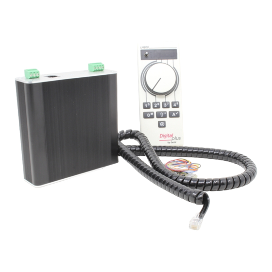
All present and correct?
Please check, whether all the components of the SET-02 have been
delivered:
LH200 - Knob based Engineer's Throttle
LV200 - Power Station (Booster)
black coil cable with phone plugs at each end
one 4- and one 3-terminal green connector attached to the
rear of the LV200
one additional 4-terminal green connector
operating manual (this booklet)
If any component is missing, please ask your supplier for a
supplementary delivery.
Europe
Lenz Elektronik GmbH
Huettenbergstrasse 29
D-35398 Giessen
++49 (0) 6403 900 133
++49 (0) 6403 900 155
info@digital-plus.de
®
SET-02 and
North America
Lenz Agency
PO Box 143
Chelmsford, MA 01824
++1 978 250 1494
++1 978 250 1494
support@lenz.com
Advertisement
Table of Contents

Related Manuals for Lenz DIGITAL PLUS SET-02

Summary of Contents for Lenz DIGITAL PLUS SET-02
- Page 1 Welcome! Thank you for purchasing our SET-02. We would like to congratulate ® you on your acquisition of the Digital plus by Lenz SET-02 and we hope you will enjoy working with this model-railway control. The purpose of this operating manual is to explain the use of the Set and its components to you.
-
Page 2: Information Set
Digital plus by Lenz ® system, however, it would distort the data format and interfere with the fault-free transmission of data. A mixed digital operation using overhead lines and track is not permitted. In such a mode of operation, if the locomotive is sitting on the track in the wrong direction (which might be the case e.g. -
Page 3: Table Of Contents
Information SET-02 Contents Contents Quick Start Users Guide Connection and initial operation Your first operation of a DCC train SET-02 Capabilities Overview Range of possible addresses for your locomotives Locomotive functions that can be controlled Throttle Notch choices Multi unit (MU) consisting Configuring decoder features Power Station capabilities Expanding your system... - Page 4 Information SET-02 11.3 Constructing your first Multi unit (MU) consist 11.4 Displaying the locomotive address within an MU 11.5 Controlling the speed and direction of a locomotive within a MU 11.6 Controlling functions of a locomotive within a MU 11.7 Removing a locomotive from a MU 11.8 Managing the LH200 MU memory...
-
Page 5: Quick Start Users Guide
Information SET-02 Quick Start Users Guide In this section you will learn about: the few steps that you need to know to operate your SET-02 how to start your first test run In the later sections below, the whole range of functions of the SET- 02 will be explained in detail. -
Page 6: Your First Operation Of A Dcc Train
Information SET-02 Your first operation of a DCC train Let us assume that the decoder which was delivered together with SET-02 has been installed into your locomotive (either by you or by someone else) and is now on your layout. This decoder is shipped from the factory with address (number) 3. -
Page 7: Set-02 Capabilities Overview
Information SET-02 In order to switch on the light function of the locomotive decoder, press the key "0 ". Press the key once and you will turn on the light, press it again and you will turn it off. With LH200 you can control up to 9 functions in locomotive decoders. -
Page 8: Locomotive Functions That Can Be Controlled
Information SET-02 Locomotive functions that can be controlled You can address up to 9 functions in locomotive decoders (termed F0-F8). You will learn how to switch these functions on and off in the section "Switching locomotive-decoder functions on and off " which starts on page 18. -
Page 9: Power Station Capabilities
Information SET-02 Programming on the programming track A programming track is an section of track that is completely electrically isolated from the remainder of your layout. One decoder at a time can be placed on this isolated track for setting the various decoder configurations. -
Page 10: Controlling Turnouts
Information SET-02 Controlling turnouts Although the possibilities opened through SET-02 features are many and varied, SET-02 does have some limits. The LH200 contained in SET-02 is not able to control turnouts or switch magnetic articles on and off. This capability was omitted to keep the LH200 easy for a train operator. -
Page 11: The Rotary Control-Knob
Information SET-02 In normal operation the address of the locomotive which you are presently controlling is constantly shown. Points below left, in the centre and below right are helpful for adjusting the rotary control-knob and the direction switch when you take control of a different locomotive. -
Page 12: The Keys
Information SET-02 The keys Only a few well arranged keys are necessary for the controlling of your locomotives: With this key you scroll through the addresses which are saved in the "stack". When using the menu this key becomes the "ok" or check key. "Shift"... -
Page 13: The Lh200 Menus
Information SET-02 You can choose whether you want to switch off the voltage on the track by pressing this key or whether only the locomotive, whose address you presently see on the display, is to be stopped. You will learn how you set this function from the section "Configuring your SET-02"... -
Page 14: Entering Numeric Values Within A Menu
Information SET-02 Entering numeric values within a menu To enter numeric values within a menu, always follow the same procedure: Choose the relevant digit with the appropriate key and alter the value by turning the knob. This procedure is described in more detail in the following section. - Page 15 Information SET-02 Example 1: entering a 2-digit digit address In the following example the current address "03" in the stack is changed to "46". The locomotive with the address 3 will remain running on the layout with the LH200 knob position that was present before the menu option was selected.
- Page 16 Information SET-02 The furthest right digit of the address display now flashes. Alter the value of this digit by turning the rotary control-knob to the right (value increases) or to the left (value decreases). In this example the value is altered to 4.
-
Page 17: Operating A Locomotive With Your Lh200
Information SET-02 Example: You want to alter address 1234 to 1334. Here you only have to select the second digit from the left with key '2' and then alter its value. When finished simply confirm the selection with "A " key Operating a Locomotive with your LH200 In this section you will learn about: how the rotary control-knob and the direction switch are used to... -
Page 18: Switching The Locomotive Decoder Functions On And Off
Information SET-02 Now place the direction switch in the correct position, up (forwards) or down (backwards). If the upper dot appears in the middle of the display, then you must move the switch up (the forwards position). If the lower dot appears in the middle of the display you must move the switch down switch it down (the backwards position backwards). -
Page 19: Matching The Lh200'S Throttle Notches To The Decoder's Speed Steps
Information SET-02 switches function 0 on or off switches function 1 on or (normally the direction-dependent front lighting). switches function 3 on or switches function 2 on or off switches function 4 on or off For functions 5 through 8 you need 2 keystrokes. switches function switches function 5 on or off... - Page 20 Information SET-02 decoder's speed step mode. The LH200 default is 28 throttle notches which in combination with the smoothness of the LH200 rotary control knob provides the smoothness that most modelers desire. To change the number of throttle notches for a specific locomotive address the LH200 provides a special menu that lets you easily select a different option.
-
Page 21: Programming On The Main - Pom (Operations Mode Programming)
10 Programming on the Main – PoM (operations mode programming) In this section you will learn about: ® what "programming" actually means for Digital plus by Lenz devices which features can be altered through POM programming step by step example for POM programming 10.1 What does programming mean and what is its use? - Page 22 You can also get these documents by sending LSSAE / pre-paid envelope to Lenz Elektronik GmbH or from our WWW site.
-
Page 23: Which Features Can Be Altered With The Help Of Pom
Information SET-02 Example: binary presentation of CV29 Different settings are saved in this CV. Whether a certain setting is switched on or off, is determined by one of the 8 switches (bits): switch no. switched on (=bit set "1") switched off (=bit deleted "0") locomotive runs forward if locomotive runs backwards if direction switch points 'up'... -
Page 24: Which Locomotive Decoders Can Have Their Features Altered With The Help Of Pom
10.3 Which locomotive decoders can have their features altered with the help of PoM? All Lenz Digital plus locomotive decoders ending with the XF- and XS-series are PoM capable. If you employ locomotive decoders from different producers, please check in the documentation whether these decoders are also PoM capable. -
Page 25: Setting And Deleting Bits Via Pom - Step By Step
Information SET-02 In the following example value 10 shall be set for the acceleration rate. Select the next digit, When you do this the value 0 is taken over for the fourth digit from the left. Now the second digit from the right flashes. - Page 26 Information SET-02 On the very left a "C" is displayed. Now enter the number of the CV that you want to alter. The entire right-hand digit of the address display now flashes. Alter the value of this digit by turning the rotary control-knob to the right (value increases) or to the left (value decreases).
- Page 27 Information SET-02 DIGITAL plus...
-
Page 28: Error Message When Using Pom Programming
Information SET-02 You can now proceed as in the previous example above which explains how you program a numerical value. Important note: When using PoM, values can only be set, they cannot be read out. You can check whether the programming was successful or not by testing the actual alteration of the feature in operation. -
Page 29: Head To Head, Head To Tail, And Tail To Tail Operation
Information SET-02 All locomotives with the same Multi Unit (MU) address respond to the speed and direction information sent to the MU address. Most decoders do not respond to functions sent to the MU address. To access the functions that are controlled by a decoder that is in a consist, simply use its original locomotive address. - Page 30 Information SET-02 Set the direction switch so that the locomotive will operate in the proper direction when added to the consist. In this example #3 will operate in the same direction as the consist. Enter the LH200 menu. Scroll through the menu until the MU is shown and confirm the selection with "A "...
-
Page 31: Displaying The Locomotive Address Within An Mu
Information SET-02 Set the direction switch so that the locomotive will operate in the proper direction when added to the consist. In this example #4 will operate in the reverse direction as the consist. Enter the LH200 menu. Scroll through the menu until the MU is shown and confirm the selection with the "A "... -
Page 32: Controlling The Speed And Direction Of A Locomotive Within A Mu
Information SET-02 11.5 Controlling the speed and direction of a locomotive within a MU The speed and direction of all locomotives in a MU can be controlled whenever either the MU address or any locomotive within the MU is on the LH200 display. 11.6 Controlling functions of a locomotive within a MU You can control the functions of any locomotives in a MU whenever the desired locomotive address within the MU is on the... -
Page 33: Managing The Lh200 Mu Memory
Information SET-02 To delete the locomotive from the MU irreversibly, press the "A " key a second time. Now the multiple multi unit address is displayed again. When you have deleted the last locomotive address from the MU, the MU itself is deleted and the next locomotive address in the queue will be displayed on the LH200 display. -
Page 34: Configuring Your Set-02
Information SET-02 12 Configuring your SET-02 In this section you will learn about: configuring your LH200 The SET-02 can be configured by setting values in the system menu. SET-02 system settings are items that affect not only individual locomotives, but the entire system. For example, the size of the stack is such a system feature, as is the display of the software version. -
Page 35: Programming On The Programming Track
Information SET-02 13 Programming on the Programming Track In this section you will learn: what a programming track is the difference between "Programming in operational mode (POM)" and "Programming on the programming track" when it is necessary to use this programming method how to install a programming track detailed example on how to proceed step by step. -
Page 36: When Is It Necessary To Program On The Programming Track
Information SET-02 Caution: Every decoder which receives programming track commands will change their CVs. This means that if you do not use a programming track that is totally isolated from your layout, all your locomotives on the layout will at the same time change their CVs at to the value you program. -
Page 37: Programming On The Programming Track" - Step By Step Instructions
Information SET-02 13.5 Programming on the programming track" – step by step instructions Pull out the 4-terminal green connector UVJK of the power station LV200 which is connected to your LH200. This disconnects the tracks of your model railway from the power station and switches off the power supply. - Page 38 Digital plus by Lenz ® XF and XS series decoders and decoders with version 4.1 or 5.1 support these features. If you are using a different manufacturer's decoder, check with its operating manual to see if you can use this shortcut mode.
-
Page 39: Expanding Set-02
Information SET-02 14 Expanding SET-02 In this section you will learn: how to connect more input devices (handheld controls etc.) to your SET-02 how you satisfy a larger power requirement for your model railway how to expand beyond the capabilities of SET-02 by adding an LZ100 command station in order to increase the amount of saved locomotive data, to be able to evaluate feedback and to utilise more handhelds or power stations. -
Page 40: Adding An X-Bus To Allow Additional Input Devices
Information SET-02 14.1 Adding an X-Bus to allow additional input devices Your Digital plus by Lenz ® SET-02 has the ability to easily expand using its support of the X-Bus. The X-Bus is a leading model railroad high speed network protocol. It is based on the electronic industry standard RS-485 hardware. -
Page 41: Special Information On Operating X-Bus-Devices
Information SET-02 device. This means that they may be unplugged and plugged in again as often as desired during operation. If you do this you can achieve a high level of mobility through these devices. You can attach several X-Bus connectors to your model railway layout at convenient locations, so that you can always plug in your input device where you need it at the time. -
Page 42: More Power Through More Power Stations
As with conventionally operated systems and layouts, a sufficient supply of electricity to the system is a precondition for the sure and safe functioning Digital plus by Lenz ® systems. Locomotives, coach lights, points, signals etc. receive their power and control information from the power station. -
Page 43: Expanding Beyond The Capabilities Of Set-02 Using A Lz100 Command Station
LZ100 to your SET-02. This expands your system to a full ® professional Digital plus by Lenz SET-01 system. Once you add an LZ100 to your system the LH200 is relieved of its command station tasks. The LZ100 is now the "heart" of your... -
Page 44: Technical Appendix
SET-02's command station. Please order this together with a separate operating manual from your DCC supplier or directly from Lenz Elektronik GmbH. The features of your DCC system are now determined by the software version of LZ100. Version 3 will have the following features:... -
Page 45: Messages On The Display
Information SET-02 To scroll through the stack, use the key. You can configure the number of cards you desire to scroll through. It is possible to set LH200 so that you only switch back and forth between the first and second index cards. Or you may wish to see only the first 4 cards. -
Page 46: Permissible Supply Voltage (Input Voltage)
Information SET-02 15.3.1 Permissible supply voltage (input voltage) The LV200 is designed for the following input voltages: AC (TR200): 15 Volts AC DC (Aristo Craft ART-5460) 19V DC DC (LGB - Jumbo): 16-24V DC (note 22 is the max) Generic Transformer: O and S scales 15V AC Large Scale 15V AC or 22V DC 15.3.2 Voltage on the track (output voltage) -
Page 47: Connecting The Lv200 To The Layout
Information SET-02 alone, however, is not enough to enable operation. It must first be amplified in such a way that, in addition to the information, the required current- supply can also flow. This amplification is the task of the LV200. 15.4.1 Connecting the LV200 to the layout On the back of LV200 you will find the following connections: Connect the transformer... -
Page 48: The Luminous Diode
Information SET-02 15.4.2 The luminous diode The luminous diode at the front of the LV200 provides information on the operating situation: green, Everything is ok, there is operating voltage and the DCC signal is being constant: sent to the track. green, The LV200 is not receiving a digital signal via the terminals C, D. -
Page 49: Installation Considerations
Information SET-02 Pin # Color Description Pin 1 White "C" Control Bus Connection Pin 2 Black Ground "M" Pin 3 - RS-485 "B" Pin 4 Green + RS-485 "A" Pin 5 Yellow +12 volts "L" Pin 6 Blue "D" Control Bus Connection 15.4.4 Installation considerations There must not be a capacitor connected to the track for interference control. -
Page 50: Advice On The Wiring Of The Model Railway
® Digital plus by Lenz system, however, it would only distort the data format and interfere with the fault-free transmission of data. Important: A mixed digital operation using overhead and track lines is not permitted. In such a mode of operation, if the locomotive is sitting on... -
Page 51: Connecting A Reverse Loop
Information SET-02 15.5.1 Connecting a reverse loop Lenz GmbH produces an automatic reversing module (LK100) which can be used to easily wire complex automatic reversing sections. While these units are invaluable in some cases they are not absolutely needed for DCC operations. Following is an example on how a very simple reversing section can be built. -
Page 52: Common Rail Wiring
Lenz has chosen to leave the option of the location of the common up to the individual operator. The LV200 is completely opto- isolated. -
Page 53: Wiring The X-Bus
Information SET-02 In order to prevent the digital operation from being influenced by the normal DC and vice versa, when a sectioning gap is being driven over, install the sectioning module LT100. At the gap dividing digital from analog operation, you must take steps to prevent interference between the 2 systems when a locomotive crosses the gap. - Page 54 Information SET-02 Connection Board LA150 21150 Pin Assignments from solder side Make sure that you do not mix up the cables of the terminals L and M. This could result in a short in the connected input devices. The devices exchange information with the command station via the cables at the terminals A and B.
-
Page 55: Programming Using "Register-Mode
X-Bus you can increase the length to up to 3000 ft. without problems. 15.8 Programming using "Register-mode" ® Older Digital plus by Lenz decoders (produced before 1996) and some decoders from... -
Page 56: Bits And Bytes - Conversion Help
Information SET-02 The range of values which may be used is from 1 to 99. If you do not want to program register 1, but a different one, press Now you can scroll using the "Shift" key or determine the number using the rotary control-knob. -
Page 57: Glossary
"Index-card box" enabling fast selection of a locomotive address. NMRA National Model Railroad Association NMRA DCC A standard developed by the NMRA based on Lenz Digital plus, Standards and which determines the transfer of information to locomotive decoders and accessory decoders. These standards define the interchange of decoders produced by different manufacturers. -
Page 58: Troubleshooting Guide
Information SET-02 16 Troubleshooting Guide Malfunction Possible cause Correction SET-02 Power supply is interrupted, Ensure that operational transformer is not plugged into transformer is on, has not (LED on LV200 does an outlet or " U", "V" wires are overloaded or shut off, not light up) connected check... - Page 59 Information SET-02 Locomotive lighting Locomotive decoder is set at Alter the throttle position (F0) can not be running-notch mode 28. The mode of the LH200 to 28 switched on relevant address is to be found set the locomotive decoder in the LH200 in running-notch to 14 Throttle notch mode 14.
-
Page 60: Radio And Television Interference
Federal Communications Commissions rules. 18 Warranty Lenz GmbH does everything it can do to ensure that its products are free from defects and will operate for the life of your model railroad equipment. From time to time even the best engineered products fail either due to a faulty part or from accidental mistakes in installation. - Page 61 The user must pay shipping to and from the authorized Lenz GmbH warranty center during this portion of the warranty period. This warranty is not valid if the user has altered, intentionally...
- Page 62 Information SET-02 © 1999 Lenz GmbH, All Rights Reserved...
Need help?
Do you have a question about the DIGITAL PLUS SET-02 and is the answer not in the manual?
Questions and answers