Table of Contents
Advertisement
Quick Links
IMPORTANT: It is most important that both the customer
and the installation
engineer,
in this
booklet,
but must be satisfied that all the following
conditions have been complied with.
This stove must not be used with any solid fuel; it is only
suitable for Natural Gas or liquefied petroleum gas (LPG)
according to the burner unit supplied. Ensure that the local
gas distribution conditions, the gas pressure and the adjust-
ment of the stove are compatible. Check that the burner
data plate (attached to the burner unit) corresponds with the
type of gas to be used ie. Natural Gas or LPG.
The site of the stove, the chimney, the flue and hearth etc., must comply with current Building regulations and Codes of
Practice before the stove is installed. The chimney flue outlet must be correctly positioned to align with the flue outlet on
the stove that you have bought. Connection to the chimney, the job of the installation engineer, is detailed in Section 1
LOCATION AND RECOMMENDED HEARTH SPECIFICATION: Your hearth should protrude at least 150mm (6") in front
of the stove body and be at least 12mm (1/2") thick. In most buildings with solid concrete floors this requirement will be
met by the floor itself. There should be a gap of at least 150mm (6") on either side of the stove, more if possible as the
greater the space the greater the amount of heat being released into the room. If the stove is to be fitted into an existing
opening there should be a minimum of 150mm (6") clearance on both sides, with the back of the flue diverter box 15mm
clear of the rear wall. On all stove installations no combustible material should cover the hearth, or be placed any closer
then 225mm (9") from the stove. This includes carpeting and other combustible floor coverings.
SAFETY REMINDERS: Tiger stoves are efficient appliances giving off convected, conducted and radiated heat. All the
surfaces of the stove - except the controls - are working surfaces and become hot in use. They must not be touched or
have any combustible objects or material placed on or near them. Adequate precautions should always be taken to protect
children, the elderly, the infirm and pets, etc. from coming into contact with the stove.
V125 Flue Spillage Monitoring System: Tiger stoves are fitted with an oxygen depletion sensitive pilot.
SECTION 1 - STOVE ASSEMBLY, INSTALLATION + COMMISSIONING
TO BE CARRIED OUT ONLY BY THE INSTALLATION ENGINEER.
MOST IMPORTANT: Before installing the stove, check that the burner data plate corresponds with the type of gas to be
used, ie. Natural Gas or LPG. Please make sure the customer is familiar with the initial lighting and operating procedures
before leaving the site and that this instruction booklet is left with them. Please check that the following components, deliv-
ered in 2 boxes, are included before you start on the assembly:
Box 1: Burner Unit and coal or log set.
Box 2: Stove Body inc. baffle and flue diverter and Allen Key for locking door handle.
legs loosely to the central bridging member. Attach to the underside of the stove using the bolts supplied before fully tight-
ening.
OPERATING INSTRUCTIONS
For Tiger Stove with V125 Gas Burner
With Coals or Logs (Natural Gas or LPG)
LEAVE THIS DOCUMENT WITH THE HOUSEHOLDER !
not only follow the instructions
STANDARD LEGS: Attach the legs if required. It is suggested that the two
legs with fixing holes be fitted to the back of the stove, for neater appear-
ance. If the hearth is uneven, fit one or more extra washers between any leg
and the stove body to lengthen it.
COOKTOP KIT OPTION (supplied separately): Open the door and remove
the two bolts located to the left and right inside the underneath of the stand-
ard top. Remove and discard the standard top, taking care not to damage
the fibre seal. Fit the 'wings' to the cooktop and bolt the whole assembly
back onto the stove body. Do not over tighten.
HI-LEG KIT OPTION (supplied separately): Remove and discard the gas
control access hatch in the right-hand leg. Assemble the left, and right hi-
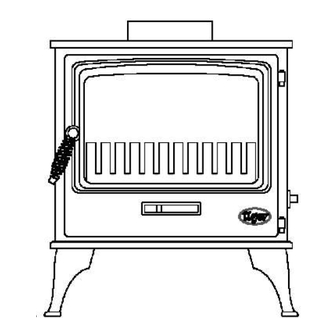
CAST-IRON GAS STOVE
INSTALLATION AND
TECHNICAL DATA Natural Gas (G20)
Gas flow rate (m³/h) 0.52
Input (kW)
Burner
Injector
Injector pressure
(high flame)
1
LPG (G31)
0.19
5
4.8
P4 48 Co Pilot
P4 49 Co Pilot
NG20/A/400/M9/BE
LP37/A/400/M9/BE
BRAY 82/460
BRAY 92/200
8.0 mbar
20 mbar
Advertisement
Table of Contents

Related Manuals for Tiger GAS


Summary of Contents for Tiger GAS
-
Page 1: Operating Instructions
TO BE CARRIED OUT ONLY BY THE INSTALLATION ENGINEER. MOST IMPORTANT: Before installing the stove, check that the burner data plate corresponds with the type of gas to be used, ie. Natural Gas or LPG. Please make sure the customer is familiar with the initial lighting and operating procedures before leaving the site and that this instruction booklet is left with them. - Page 2 GAS PRESSURE: Make sure that there is adequate gas pressure and volume to the stove. The relevant pressures are on the data plate. Ensure that the gas pressure to the stove is maintained when it is operating at the same time as other ap- pliances in the building.
- Page 3 When the stove is not being used for long periods, i.e. in the summer then we advise that the gas supply is turned off at the isolation tap.
- Page 4 Tel: 0161 703 8157 Designed in England by Glyn Hughes Design. The Tiger Stove is registered design UK3019213, and is fully protected by Copyright © and UK Design Right, Glyn Hughes 1999/2005. Assembled in Gao Zhuangzi Village, Tianjin, China from components manufactured in the USA, UK, Japan and China.
Need help?
Do you have a question about the GAS and is the answer not in the manual?
Questions and answers