Table of Contents
Advertisement
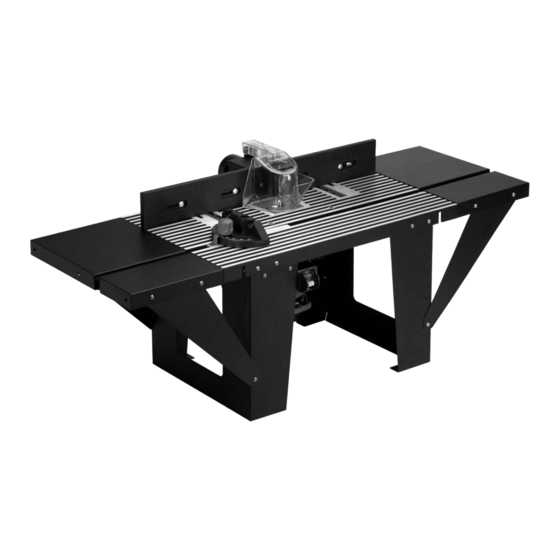
Benchtop
Router Table
Read and Save these Instructions.
IMPORTANT:
Keep Instructions for Future Reference.
IMPORTANT:
Please retain these instructions for future reference.
If you encounter any problems or difficulties please do not return this product to the store.
Please contact our toll free customer service department at:
1-800-423-3598
1-310-522-9008 (California only)
1-310-522-9066 Fax
MODEL #480410
1431 VIA PLATA,
LONG BEACH, CA 90810-1462
Made in China.
www.handtoolonline.com
© COPYRIGHT 2003,
ALLTRADE TOOLS LLC. REV. 1
Advertisement
Table of Contents

Summary of Contents for Mastergrip 480410
-
Page 1: Router Table
MODEL #480410 Benchtop Router Table IMPORTANT: Read and Save these Instructions. IMPORTANT: Keep Instructions for Future Reference. 1431 VIA PLATA, Please retain these instructions for future reference. LONG BEACH, CA 90810-1462 If you encounter any problems or difficulties please do not return this product to the store. -
Page 2: Table Of Contents
Table of Contents Content Page Router Safety Instructions ......... 3-5 Parts . -
Page 3: Router Safety Instructions
WARNING Read all Instructions • Failure to follow instructions may result in electric shock, fire and/or serious injury. Router Safety Instructions Operation Area • Do not operate power tools in the presence of flammable liquids, gases or dust. • Always make sure the work surface is free from nails and other foreign objects. •... - Page 4 Power Tool Safety Cont. • Never carry tool by the power cord or use the cord to pull the plug from the outlet. Keep cord away from heat, oil, sharp edges or moving parts. Replace damaged cords immediately. • When operating a power tool outside, use an outdoor extension cord marked “WA” or “W”. Router (Only) Use and Care •...
- Page 5 Power Tool Safety Cont. • Some routers, when positioned in an upside down position (such as on a router table), will drop or fall out of the router base when the base clamp is loosened to adjust height and depth of cut. Therefore, it is extremely important to support the router from below when making these adjustments or whenever the base clamp is loosened.
-
Page 6: Parts
Parts Make sure all parts pictured below are included in package. -
Page 7: Tools And Fasteners Required
Tools and Fasteners Required Tools Required • 1/4" (6,35mm) Slotted and #1 Phillips screwdriver. • Small or medium sized adjustable wrench (or a set of nut drivers, open end wrenches or box wrenches) • Electrical drill • One or more of the following drill bit sizes: 1/8" (3,18mm), 3/16" (4,76mm), 1/4" (6,35mm), 9/32" (7,14mm), or 11/32"... -
Page 8: Router Table Operation And Assembly
Router Table Operation and Assembly Read Instruction Manual thoroughly before operating router table. For your safety heed all warnings and recommendations. Product These fasteners will be used for the majority of fastening of the router table. Use these fasteners in this order for optimal fastening. Attach the leg with the outlet box to the table as shown. -
Page 9: Fence Assembly Instructions
Router Table Operation and Assembly cont. Attach all 4 extension supports. Turn router table over. Table should Secure extension supports in 3 places. look like this. Fence Assembly Instructions Fence Using the smallest carriage bolts, fasten fence face Fasten fence face plate to vacuum adapter bracket plate to table bracket fence. - Page 10 Fence Assembly Instructions cont. Place completed fence bracket on table so holes line up with table slits. There are 2 remaining lengths of carriage bolts (one medium and one long). Use the medium one on hole #1 and long one on hole #2. See completed. Insert pin into chip guard and fence OPTIONAL: Use holes on the bottom of table legs to mount table to bracket as shown.
-
Page 11: Table 1 (For Installing The Router)
Table 1 (For Installing the Router) Router Model # Number Hole Size Recommended Type of Holes Diameter Fasteners Porter Cable #7539 11/32" Four 5/16-18 x 7/8" Long Flat Base Plate Removed; Countersunk Head Screws Screws Only Porter Cable #690 & 6931 7/32"... -
Page 12: Table 1A Metric (For Installing The Router)
Table 1a Metric (For Installing the Router) Router Model # Number Hole Size Recommended Type of Holes Diameter Fasteners Porter Cable #7539 8,7mm Four 7,9mm x 22,2mm Long Flat Base Plate Removed; Countersunk Head Screws Screws Only Porter Cable #690 & 6931 5,3mm Three #10-24 x 19,0mm Long Flat Base Plate Removed;... -
Page 13: Installing The Adaptor Plate
Installing the Adaptor Plate Using Table 1/1a (pg.11-12) Insert 1/4" (6,35mm) Shaft through Using the template and router base, and the template provided at paper template into collet of router. locate and mark the center of router the end of this manual, mark plate retaining screws. - Page 14 Installing the Adaptor Plate cont. Using adhesive tape, secure Rotate the template and router adapter Using Table1/1a (pg.11-12), drill template and adapter on all on to its back and mark with center the correct hole size on all marked four edges. punch holes for router retaining spots.
-
Page 15: Installing The Adaptor Plate
Installing the Adaptor Plate cont. (Figure 1) Countersunk Screw Installing the Adapter Plate: • Figure1 shows the correct installation of a countersunk screw. The countersunk screw must be flush or below the top of the adapter plate. If the screw protrudes above the adapter plate, the adapter plate may not properly seat against the bottom of the router table. -
Page 16: Attaching Router Power Cord To The Switch Box
Attaching Router Power Cord to the Switch Box Plug router into the switch box. Make sure to secure Attach wet/dry vacuum to router table. Be sure that all left over cord away from moving parts. cords are secured away from moving parts or components. -
Page 17: Operating The Switch Box
Operating the Switch Box Removable Safety Key prevents accidental switching Switch box On/Off positions with removable safety key “on” of Router. inserted. Operating the Switch Box 1. Make sure the switch on the router is turned ON (It maybe necessary to leave router in the lock on position) and the switch box lever is in the OFF position. -
Page 18: Installing And Adjusting Router Bit
Installing and Adjusting Router Bit Installing the Router Bit 1. Make sure the router bit is the right size for your router. 2. Install the bit so that the router collet engages 3/4" (19,05mm) of the router bit shank. 3. If the shank of the router bit bottoms out in the collet, back out the router bit approximately 1/16"... -
Page 19: Attaching Wet/Dry Vac To Fence
Using the Router Table cont. Fence adjustments sliding along Fence adjustments sliding across table Mitre slide adjustment. table length are used to control width. Adjust the amount of material the width of the opening along removed with each pass. side the router bit. Attaching Wet/Dry Vac to Fence Attaching Wet/Dry Vac to Fence •... -
Page 20: Attaching Tabletop Inserts To The Router Table
Attaching Tabletop Inserts to the Router Table Table Top Inserts to the Router Table This router table comes with three tabletop inserts in the following hole sizes: • 1-1/4" (3,18cm) diameter, for use with router bits with diameters up to 1-1/8" (2,86cm) •...
Need help?
Do you have a question about the 480410 and is the answer not in the manual?
Questions and answers