Table of Contents
Advertisement
This manual covers equipment which is no
longer in production by The Lincoln Electric Co.
Speci cations and availability of optional
features may have changed.
Safety Depends on You
LiquidArc machines are designed
and built with safety in mind.
However, your overall safety can
be increased by proper installation
... and thoughtful operation on
your part. DO NOT INSTALL,
OPERATE OR REPAIR THIS
EQUIPMENT WITHOUT READ-
ING THIS MANUAL AND THE
SAFETY PRECAUTIONS CON-
TAINED THROUGHOUT. And,
most importantly, think before you
act and be careful.
Made exclusive for Australia
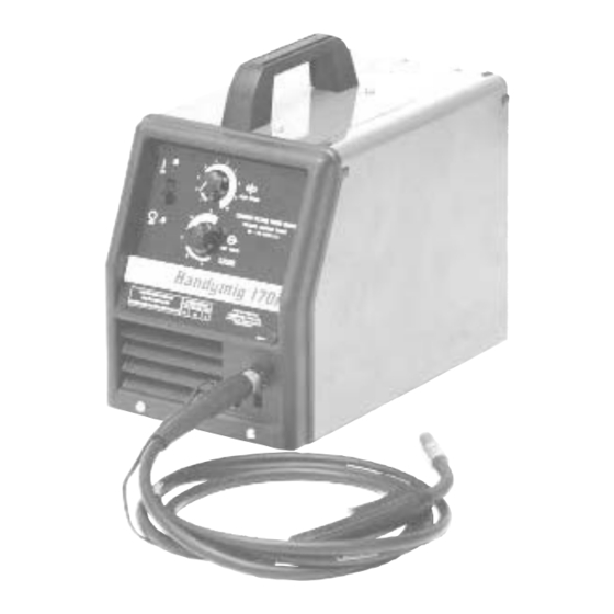
Handymig 170i
For use with machine Code Numbers
OPERATOR'S MANUAL
A Division of Lincoln Electric Company (Aust) Ply Ltd A.B.N. 36 000 040 308
35 Bryant Street, Padstow, NSW2211, Australia
Copyright © 2000 Lincoln Global Inc.
10984
IM796
April, 2006
Advertisement
Table of Contents
Troubleshooting

Related Manuals for liquidarc Handymig 170i

Summary of Contents for liquidarc Handymig 170i
- Page 1 The Lincoln Electric Co. Speci cations and availability of optional features may have changed. Safety Depends on You LiquidArc machines are designed and built with safety in mind. However, your overall safety can be increased by proper installation ...
- Page 2 SAFETY WARNING ARC WELDING CAN BE HAZARDOUS. PROTECT YOURSELF AND OTHERS FROM POSSIBLE SERIOUS INJURY OR DEATH. KEEP CHILDREN AWAY. PACEMAKER WEARERS SHOULD CONSULT WITH THEIR DOCTOR BEFORE OPERATING. For more detailed information it is strongly recommended that you purchase a copy of "Safety in Welding and Cutting - ANSI Standard Z49.1"...
- Page 3 SAFETY ELECTRIC AND 2.i.4 Connect the work cable to the work piece as close as possible to the area being welded. (This is also a good MAGNETIC FIELDS practice to eliminate a common problem on welding - a poor work connection. may be dangerous 2.i.5 Do not work next to the welding power source.
-
Page 4: Electric Shock Can Kill
SAFETY ARC RAYS can burn. ELECTRIC SHOCK can 4.a. Use a shield with the proper filter and cover kill. plates to protect your eyes from sparks and 3.a. The electrode and work (or ground) circuits the rays of the arc when welding or observing are electrically “hot”... - Page 5 SAFETY WELDING SPARKS can CYLINDER may explode cause fire or explosion. if damaged. 6.a. Remove fire hazards from the welding area. 7.a. Use only compressed gas cylinders If this is not possible, cover them to prevent containing the correct shielding gas for the the welding sparks from starting a fire.
-
Page 6: Assessment Of Area
Products are: sure. • For use with other Lincoln Electric/LiquidArc equipment. • Designed for industrial and professional use. Maintenance of the Welding Equipment Introduction The welding equipment should be routinely maintained according to the manufacturer’s recommendations. - Page 7 for selecting a QUALITY product by Lincoln Electric. We want you Thank You to take pride in operating this Lincoln Electric Company product ••• as much pride as we have in bringing this product to you! Please Examine Carton and Equipment For Damage Immediately When this equipment is shipped, title passes to the purchaser upon receipt by the carrier.
-
Page 8: Table Of Contents
Tilting.......................A-3 Output Connections ....................A-3 Work Clamp Installation ..................A-3 Work Cable Installation ...................A-4 Gun Installation......................A-4 Connecting Gun Cable to the Handymig 170i..........A-4 Gas Connection .....................A-4 Input Connections....................A-5 Electrical Input Connection for Rated Output ............A-6 Line Cord Connection ..................A-6 Operation ......................Section B Safety Precautions ....................B-1... - Page 9 Changing Drive Roll ..................D-2 Changing Liner....................D-3 Gun Handle Parts ...................D-3 Ground Test Procedure ..................D-4 Troubleshooting ....................Section E Safety Precautions....................E-1 How to Use Troubleshooting Guide...............E-1 Troubleshooting Guide................E-2 thru E-4 Wiring Diagrams ....................Section F Handymig 170i Wiring Diagram ................F-1 Handymig 170i Parts ................P463,P202,P189 Handymig 170i...
-
Page 10: Installation
INSTALLATION TECHNICAL SPECIFICATIONS – Handymig 170i INPUT – SINGLE PHASE ONLY Standard Voltage/Frequency AS1966.1 240V/50Hz Rated Input Current 12.7 Amps RATED OUTPUT Duty Cycle Amps Volts at Rated Amperes OUTPUT Welding Current Range Maximum Open Circuit Voltage Auxiliary Power Rated DC Output: 30 – 170 amps... -
Page 11: Identify And Locate Components
• Machine must be plugged into a receptacle which is grounded per any national, local or other applicable electrical codes. • The Handymig 170i power switch is to be in the OFF (“O”) position when installing work cable and gun and when connecting power cord to input power. -
Page 12: Select Suitable Location
Work Clamp Installation STACKING Attach the work clamp per the following: Refer to Figure A-3. Handymig 170i’s cannot be stacked. TILTING Each machine must be placed on a secure, level sur- face, either directly or on the recommended cart. The machine may topple over if this procedure is not fol- lowed. -
Page 13: Work Cable Installation
The Handymig 170i is supplied with a mixed gas Regulator and a 3m gas hose. A cylinder of an appro- As shipped from the factory, the Handymig 170i gun is priate shielding gas must be obtained from your gas ready to feed .023" – .025"(.6mm) solid wire. If .030"- distributor. -
Page 14: Input Connections
• Keep cylinder away from welding hose to the outlet fitting of the flow regulator and tighten the union nut securely with a wrench. Connect the other end to the Handymig 170i Gas WARNING Solenoid Inlet Fitting (5/8-18 female threads — for or other live electrical circuits. -
Page 15: Electrical Input Connection For Rated Output
Handymig 170i. • Use only grounded receptacle. • Do not touch electrically “hot” parts inside Handymig 170i. • Have qualified personnel do the maintenance and troubleshooting work. Line Cord Connection A three conductor line cord with a 15 amp, 240 volt, three pin plug is factory installed. -
Page 16: Operation
RECOMMENDED PROCESSES WELDING SPARKS can The Handymig 170i can be used for welding mild steel cause fire or explosion. using the GMAW, single pass, process which requires a supply of shielding gas or it can be used with the •... -
Page 17: Welding Capability
OPERATION WELDING CAPABILITY The Handymig 170i is rated at 130 amps, 20 volts, at 20% duty cycle on a ten minute basis. It is capable of higher output currents at lower duty cycles. . FIGURE B.1a LIMITATIONS Arc Gouging cannot be performed with the Handymig 170i. -
Page 18: Welding Operations
5/8” (16 mm) diameter shaft and held in place with the previously removed hardware. Also make certain the start end of the wire, which may pro- trude through the side of the spool does not contact any metallic case parts. Handymig 170i... -
Page 19: Wire Threading
(4), over the drive roll (3), and into the outgoing guide tube (5). 8. Turn the Handymig 170i ON (“I”). 5. Close the idle roll arm and latch the spring loaded pressure arm (2) in place. Rotate the spool coun- terclockwise if required to take up extra slack in 9. -
Page 20: Making A Weld
PROCESS GUIDELINES wire being used and that the gas supply, if required, is turned on. The Handymig 170i can be used for welding mild steel using the GMAW, single pass, process which requires 5. When using Innershield electrode, remove the gas a supply of shielding gas or it can be used for the self- nozzle and install the gasless nozzle. -
Page 21: Changing Over To Feed Other Wire Sizes
0.023” – .025" (0.6 mm) diameter wire. To essary accessories for this conversion and are provid- operate the Handymig 170i with other sizes of wire, it ed for this purpose. The following conversions should maybe necessary to change the contact tip, change be made using the contents of this kit: drive roll and gun liner configuration. -
Page 22: Application Chart
APPLICATION CHART Handymig 170i... -
Page 23: Maintenance
170i. Use only grounded recepta- the gun. Using low pressure air, gently blow out the cle. Do not touch electrically cable liner from the gas diffuser end. “hot” parts inside Handymig 170i. CAUTION • Have qualified personnel do the maintenance and trouble shoot- Excessive pressure at the start may cause the dirt ing work. -
Page 24: Component Replacement Procedures
5. Turn the power switch to OFF (marked “O”). 6. Loosen the drive roll set screw with the 5/64" (2.0 mm) hex wrench supplied. 7. Remove the drive roll, flip over and reinstall with the .030/.035" (0.8/0.9 mm) groove (the larger groove) closest to the gearbox. Handymig 170i... -
Page 25: Changing Liner
7. With the gas nozzle and diffuser removed from the gun tube, be sure the cable is straight, and then trim the liner to the length shown in the Figure D.2. Remove any burrs from the end of the liner. Handymig 170i FIGURE D.3... -
Page 26: Ground Test Procedure
‘active’ & ‘neutral’ ter- minals of the 240V input plug and the other to the jumper on pins 4 & 5 in the shorting socket. Apply the test. (Minimum resistance 1M•) Handymig 170i... -
Page 27: Troubleshooting
CAUTION If for any reason you do not understand the test procedures or are unable to perform the tests safely, contact your LOCAL AUTHORIZED LIQUID ARC FIELD SERVICE FACILITY for assistance before you proceed. _____________________________________________________________________ Handymig 170i... -
Page 28: Troubleshooting Guide
4. Gun trigger may be faulty. CAUTION If for any reason you do not understand the test procedures or are unable to perform the tests/repairs safely, contact your LIQUID ARC LOCAL AUTHORIZED FIELD SERVICE FACILITY for assistance before you proceed. Handymig 170i... - Page 29 CAUTION If for any reason you do not understand the test procedures or are unable to perform the tests/repairs safely, contact your LIQUID ARC LOCAL AUTHORIZED FIELD SERVICE FACILITY for assistance before you proceed. Handymig 170i...
- Page 30 8. Check liner for proper size. CAUTION If for any reason you do not understand the test procedures or are unable to perform the tests/repairs safely, contact your LIQUID ARC LOCAL AUTHORIZED FIELD SERVICE FACILITY for assistance before you proceed. Handymig 170i...
-
Page 31: Wiring Diagrams
WIRING DIAGRAMS Handymig 170i WIRING DIAGRAM: Code 10984 NOTE: This diagram is for reference only. It may not be accurate for all machines covered by this manual. The specific diagram for a particular code is pasted inside the machine on one of the enclosure panels. - Page 32 NOTES...
- Page 33 NOTES...
- Page 34 ● ● ● Do not touch electrically live parts or Keep flammable materials away. Wear eye, ear and body protection. WARNING electrode with skin or wet clothing. ● Insulate yourself from work and ground. Spanish ● ● ● No toque las partes o los electrodos Mantenga el material combustible Protéjase los ojos, los oídos y el AVISO DE...
- Page 35 ● ● ● Keep your head out of fumes. Turn power off before servicing. Do not operate with panel open or ● Use ventilation or exhaust to guards off. WARNING remove fumes from breathing zone. ● Spanish Los humos fuera de la zona de res- ●...
- Page 36 A Division of Lincoln Electric Company (Aust) Ply Ltd A.B.N. 36 000 040 308 35 Bryant Street, Padstow, NSW2211, Australia Copyright © 2000 Lincoln Global Inc.
Need help?
Do you have a question about the Handymig 170i and is the answer not in the manual?
Questions and answers