Table of Contents
Advertisement
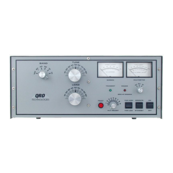
QRO HF-2500DX LINEAR AMPLIFIER
QRO HF-2500DX LINEAR AMPLIFIER
COPYRIGHT 1996 BY QRO TECHNOLOGIES, INC. ALL RIGHTS RESERVED.
THIS MANUAL OR ANY PART THERE OF MAY NOT BE REPRODUCED IN ANY FORM
WITHOUT PERMISSION FROM QRO TECHNOLOGIES, INC.
INSTRUCTION MANUAL
QRO TECHNOLOGIES, INC
QRO TECHNOLOGIES, INC
1117 West High Street
P.O. Box 939
Bryan, OH 43506 USA
Tel & Fax: (419) 636-2721
E-mail: sales@qrotec.com
Internet: http://www.qrotec.com
PUBLICATION DATE: October 1996
Advertisement
Table of Contents

Related Manuals for QRO Technologies HF-2500DX

Summary of Contents for QRO Technologies HF-2500DX
- Page 1 Tel & Fax: (419) 636-2721 E-mail: sales@qrotec.com Internet: http://www.qrotec.com PUBLICATION DATE: October 1996 COPYRIGHT 1996 BY QRO TECHNOLOGIES, INC. ALL RIGHTS RESERVED. THIS MANUAL OR ANY PART THERE OF MAY NOT BE REPRODUCED IN ANY FORM WITHOUT PERMISSION FROM QRO TECHNOLOGIES, INC.
-
Page 2: Specifications
SPECIFICATIONS Band Coverage: 160, 80, 40, 20, 17, and 15 (12 & 10 export only) meter amateur bands. 12 & 10 meter also useable in USA with proof of license and user modification. Drive Power Required: 50 to 60 watts nominal for rated output Maximum Output Power: 1,500 watts peak all modes including SSB, CW, and con- tinious carrier or modulated carrier. -
Page 3: Table Of Contents
TABLE OF CONTENTS Warranty Proprietary Notice Safety Notification Unpacking & Inspection Reshipment Instructions Top Cover Removal Transformer & Tube Installation 6, 7 Line Voltage Selection Power Block Wiring Introduction 7, 8 Location AC Power Line Considerations 8, 9 Antenna Grounding Equipment Interconnections 9, 10 Safety Interlock Switch... -
Page 4: Proprietary Notice
GU-74B (4CX800A) tetrodes which carry a separate one year warranty. During the warranty period, QRO Technologies, Inc. will repair or replace the amplifier at our option if it is defective in any way in material and workmanship. The warranty does not cover any defects resulting from improper use by the buyer or inadequate maintenance. - Page 5 ALWAYS THINK SAFETY __________________________________________________ THIS LINEAR AMPLIFIER DESCRIBED IN THIS MANUAL CONTAINS VOLTAGE HAZARDOUS TO HUMAN LIFE AND SAFETY WHICH IS CAPABLE OF INFLICTING PERSONAL INJURY. NEVER OPERATE THE AMPLIFIER WITH THE TOP COVER REMOVED AND THE TOP COVER SAFETY SWITCH DEFEATED. BEFORE REMOVING THE TOP COVER MAKE SURE THE AC LINE POWER CORD HAS BEEN DISCONNECTED FROM THE AC POWER SOURCE.
-
Page 6: Unpacking & Inspection
All irregularities should be noted. Unpack and remove each component carefully from its carton, preserving the factory packaging as much as possible. Inspect each component for any noticeable defect or damage. Notify QRO Technologies if any defect or damage is apparent. RESHIPMENT INSTRUCTIONS Use the original packaging if it is necessary to return the amplifier, transformer, or tube to QRO for servicing. -
Page 7: Line Voltage Selection Power Block Wiring
CW, and continuous or modulated carrier (e.g., RTTY, FM, SSTV). Continuous or modulated carrier operation for more than 30 minutes at or near maximum rated output power requires use of auxiliary cooling. The HF-2500DX is designed to be used with any transceiver... -
Page 8: Location
which can deliver adjustable output power from 0 to 100 watts. A grid driven input circuit using a 50 ohm 100 watt non-inductive shunt resistor feeds each 4CX800A tetrode tube which are connected in a grounded cathode configuration. An ALC circuit develops negative voltage that can be fed back to the transceiver to reduce its gain when the amplifier is overdriven. -
Page 9: Antenna
house wiring circuit, as the ratings of the wire will almost certainly be exceeded. Avoid excessively long runs of wire between your service entrance and the Amplifier. A heavy flow of current in such a line results in a voltage drop which can affect the performance of your equipment. No plug is supplied with the line cord. -
Page 10: Safety Interlock Switch
RF OUT Connect this socket to the cable coming from your antenna. Note: Use shielded cable, such as audio-type cable, for the following connections. KEY XMT Connect this socket to the T/R relay socket on your transceiver. This connector requires contacts that are normally open in the receive mode and closed in the transmit mode. This contact sinks 12 VDC to ground at 80 mA. -
Page 11: Reading The Meters
fan will cool the tubes before you turn the Amplifier off. READING THE METERS efer to Front Panel Pictorial while you read the following information: Multimeter: The Multimeter switch on the front panel of the amplifier directly below the two panel meters selects the right-hand meter functions. -
Page 12: Initial Power Up
OBSERVE THE PLATE CURRENT (IP) DURING THE WARM-UP PERIOD. IF IT STARTS TO RISE, IMMEDIATELY TURN THE AMPLIFIER OFF. THE PLATE CURRENT SHOLD NOT RISE DURING THE WARM-UP PERIOD. CALL QRO TECHNOLOGIES FOR INSTRUCTIONS. Place your transceiver in the CW mode or any mode that will provide a continuous carrier for tuneup. -
Page 13: Tune-Up Procedure
TUNE UP PROCEDURE Before making any tune up procedures, make sure your amplifier is connected to an appropriate load capable of handing at least 1,500 watts of power. Failure to do so may result is serious damage to your amplifier. When the two minute warmup cycle has been completed, the red power light will turn on. - Page 14 5. Turn the load control counterclockwise, and the screen current should start to fall. Continue to turn the load control counterclockwise until the screen current reads 25 mA. 6. Turn the tune control clockwise until the screen current reads between 50 - 100 mA. Again, turn the load control counterclockwise until the screen current reads 25 mA.
- Page 15 If you prefer a lower input SWR, use your transceiver's tuner to adjust for a better match. WARC Band Operation: The HF-2500DX will operate on the WARC bands. You may need to use the transceivers internal tuner to provide a low input SWR on these bands. Use the following band positions: 17 Meters use 15 Meter position, 12 Meters use 10 Meter position.
-
Page 16: Periodic Maintenance
feature after your Amplifier has been properly tuned. PERIODIC MAINTENANCE Make sure the Amplifier has been disconnected for the AC power source and the high voltage filter capacitors have bleed down to zero. Remove the top cover from the Amplifier at least once a year and remove the dust. Dust accumulation can help cause the variable capacitors to arc between plates. - Page 17 Multimeter inoperative in Plate Current 1. Resistors R311 LV & Bias PCB Function 2. Switch SW401A&B Meter Switch PCB 3. M-1 Multimeter 4. F303 2 Ampere Fuse Multimeter inoperative in Screen Voltage 1. Components on Screen Supply PCB Function a. Capacitors C401 or C402 b.
- Page 18 Amplifier will not key when transceiver is keyed 1. Components on LV & Bias PCB-260 to transmit a. Fuse F301 b. Bridge Rectifier D301 c. Capacitor C301 2. Resistors R305, R306 3. Operate/Standby SW4 Front Panel 4. Components on RF I/O Switch PCB a.
-
Page 19: Circuit Descriptions
Two minute warmup cycle not functioning Components on LV & Bias PCB 1. U3 555 Timer and related components 2. Transistor Q1 3. K3 Relay CIRCUIT DESCRIPTIONS Refer to the Appropriate Schematic Diagrams and PCB Layouts while you read the following paragraphs. - Page 20 Resistor R209 is a protection resistor connected in series with the Plate Voltage Circuit. If a short develops, this resistor prevents the B- from rising to the B+ potential. Thus providing protection for all the components within the B+ circuit including the 4CX800A tetrodes. Resistors R110 - R113 &...
- Page 21 (Transmit Mode). RY2 closes and the RF energy supplied by the transceiver passes though RY2's closed contacts to relay RY3. If you have selected 160, 80, or 40 meters on the band selector switch SW3, the signal passes through normally open contacts and to R607 the 50 ohm 100 watts input swamping resitor.
- Page 22 your Transceiver. Capacitors C608 & C609 form a voltage divider that couples some of the RF driving voltage to Diodes D604 & D605. When the RF driving voltage exceeds the ALC threshold, the diodes rectify the negative half cycles. Capacitor C610 filters and bypasses this voltage, while resistor R608 provides isolation.
- Page 23 across R602 and RY1. 12 VDC is then dropped across RY2 and R603. The remaining +62 VDC is dropped across resistor R604. Capacitor C601 and resistors R601 & R602 plus diode D602 form a break make delay circuit for RY1 & RY2. This helps to make the proper latching and unlatching sequence for relays K301, RY1, and RY2.
Need help?
Do you have a question about the HF-2500DX and is the answer not in the manual?
Questions and answers