Table of Contents
Advertisement
Advertisement
Table of Contents

Related Manuals for Neumann.Berlin KH 805


Summary of Contents for Neumann.Berlin KH 805
- Page 1 KH 805 Active Subwoofer with 2.1 / 0.1 BaSS Management™ Operating Manual Bedienungsanleitung Manual Utilisateur Manual de Operación georg neumann gmbh · Leipziger Str. 112 · 10117 berLin · germany teL +49 (0)30 / 41 77 24-0 · fax -50 · headoffice@neumann.com · www.neumann.com...
-
Page 2: Table Of Contents
. . . . . . . . . . . . . . . . . . . . . . . . . . . . . . . . . . . . . . . . . . . . . . . . . . . . . . . . . . 5 Installing and connecting the KH 805 . -
Page 3: Important Safety Instructions
. There are no user serviceable parts inside . Refer servicing to your Neumann service partner . Read and follow the safety and operating instructions contained in the operating manual . 2 | KH 805... - Page 4 . “Improper use” means using the product: • other than as described in this operating manual, or • under operating conditions which differ from those described herein . This will invalidate the guarantee . KH 805 | 3...
-
Page 5: The Kh 805 Subwoofer
The KH 805 subwoofer Thank you for purchasing a Neumann subwoofer . Neumann subwoofers are designed to com- plement Neumann’s extensive range of monitors . They can be used in music, broadcast, and post production studios for tracking, mixing, mastering, and home recording . They can be... -
Page 6: Product Overview
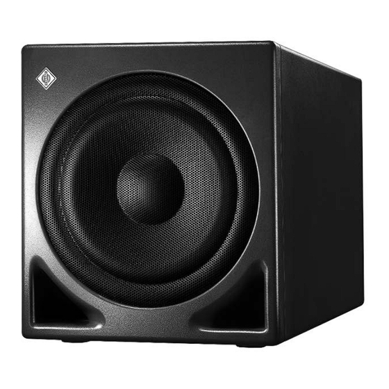
Product overview 1 Neumann logo 2 Metal grille 3 Bass reflex ports KH 805 | 5... - Page 7 L SUBWOOFER PHASE switch A PARAMETRIC EQUALIZER switch M SUBWOOFER PHASE switch B INPUT GROUND LIFT switch C Sockets INPUT | RIGHT/LFE/DAISY CHAIN INPUT | LEFT D Sockets OUTPUT | DAISY CHAIN OUTPUT | RIGHT OUTPUT | LEFT 6 | KH 805...
-
Page 8: Installing And Connecting The Kh 805
. Despite a thorough testing of the synthetics used by us, we cannot rule out the possibility of staining . Do not place the KH 805 on delicate surfaces . The bottom of the subwoofer features rubber feet which reduce the risk of scratching the sur- face and the subwoofer cabinet, and acoustically isolate the subwoofer from the surface . -
Page 9: Setting Up The Subwoofers
. The subwoofers can then be calibrated to a lower out- put level resulting in lower distortion and correspondingly cleaner low-frequency reproduction . For information on building a balanced system, please refer to the “Product Selection Guide” at www .neumann .com . 8 | KH 805... - Page 10 If you set up several subwoofers, you can utilize their mutual coupling to achieve an acoustical acoustical gain gain . The following acoustical gains are possible: Number of subwoofers Acoustical gain 0 .0 dB 6 .0 dB 9 .5 dB 12 .0 dB KH 805 | 9...
-
Page 11: Connecting The Subwoofer
17 . Connecting the subwoofer Connecting the subwoofer to an audio source Use balanced XLR cables to connect the corresponding sockets INPUT C of the KH 805 to the audio source . Connecting Use an XLR adapter (not supplied) to connect unbalanced cables (e .g . RCA cables) . Use the... - Page 12 For a simplified representation, the following connection examples show small loudspeakers in combination with the KH 805 subwoofer . Each of the examples only shows one possible combination of loudspeakers and subwoofers . For information on building a balanced system, please refer to the “Product Selection Guide”...
- Page 13 “LFE only“ subs Sub 4 Daisy Chain Three subwoofers reproducing one channel adds up to 9 .5 dB of acoustical gain which is very close to the 10 dB of gain required for the LFE channel . 12 | KH 805...
- Page 14 . The result is an uneven bass response in the room, especially if you are moving around . Always connect the subwoofer in one of the ways shown above . KH 805 | 13...
-
Page 15: Mounting The Subwoofer Electronics Externally
Connecting/disconnecting the subwoofer to/from the mains power supply To connect the KH 805 to the mains power supply: Make sure that the switch MAINS POWER 5 is set to “OFF” . Make sure that the switch MAINS VOLTAGE SELECTION 4 is set to the correct position: “AC 100/120 V”... -
Page 16: Using The Kh 805
• “OFF” to switch the subwoofer off . The LED POWER ON I goes off . There is a three second delay before sound can be heard from the KH 805 and the loud- speakers connected to the outputs in order to avoid noises (pops) from preceding equipment switched on at the same time . - Page 17 Next to or flush 0 dB mounted in an acoustically soft wall (e .g . gypsum) Free standing in an -2 dB 0 dB untreated room Free standing in a 0 dB 0 dB well-treated room 16 | KH 805...
- Page 18 Calibration using Neumann test signals Download the Neumann test signals and the instructions for use (PDF file, in English) from the KH 805 product page at www .neumann .com . Follow the steps described there . Calibration using music signals and an 80 Hz test signal Adjust the settings for the sound pressure level and the frequency response as described above .
-
Page 19: Compensating For Larger Time Of Flight (Tof) Differences
. Compensating for TOF Connect the KH 805 to an electronic time delay . Insert the electronic time delay into the differences by means of an signal path between the sockets OUTPUT D of the subwoofer and the input sockets of the electronic time delay loudspeakers . -
Page 20: Setting The Replay Level Of The Subwoofer
Right channel input mode: The LFE (WIDE) routing mode is used when there is a bass manager before the KH 805 sub- woofer . It should also be used when a DVD or Blu-ray player is connected directly to the sub- LFE (Wide) woofer (i .e . -
Page 21: Activating Ground Lift
. Never disconnect the earth pin of the mains cable from ground . Even when ground lift is activated, the pins 1 of all audio inputs remain electronically connected to each each other . 20 | KH 805... -
Page 22: Cleaning And Maintaining The Subwoofer
There is hum or buzz coming A cable is defective, the cabling is Check all cabling to eliminate the from the KH 805 when an bad, there is ground loop in the instal- cause of the problem, do not lay audio cable is connected . -
Page 23: Specifications
Protection system active POWER ON LED I lights up red Bass management active BASS MANAGEMENT LED G lights up green Product properties Mains voltage 220 … 240 or 100 … 120 V AC switchable, 50/60 Hz 22 | KH 805... - Page 24 Acoustical measurements, block diagram and pin assignment Additional technical data such as acoustical measurements, a block diagram of the KH 805 and the pin assignments of the XLR socket and the REMOTE CONTROL socket E can be found at the end of this operating manual .
-
Page 25: Accessories
Accessories Product Description FO 810 Flight case for KH 805 REK 3 Remote electronics kit SC 2 Subwoofer cable, 2 m SC 5 Subwoofer cable, 5 m SC 10 Subwoofer cable, 10 m SC 15 Subwoofer cable, 15 m SC 20... -
Page 26: Manufacturer Declarations
. This class B digital apparatus complies with the Canadian ICES-003 . Changes or modifications made to this equipment not expressly approved by Neumann may void the FCC authorization to operate this equipment . KH 805 | 25... -
Page 27: Technical Information & Glossary
. The acoustical axis is located at the midpoint of the KH 805’s bass driver . Note that the subwoofer emits very low frequencies which are emitted omnidirectionally . That is why the orientation of the subwoofer cabinet in the room does not matter . - Page 28 . Examples of how to calculate sound pressure levels as a function of the input signal levels and input and output levels of the KH 805: Absolute voltage level of...
- Page 29 5 .1 system . The designation “LFE channel” always refers to the source and not to the loudspeakers . Power The high efficiency power amplifier of the KH 805 minimizes power dissipation and is run in bridged amplifier mode to minimize distortion .
-
Page 30: System Block Diagram
NOTA: A la punta de la hembra llega una tensión de 9 V DC para que un LED pueda indicar el estado de la función Bass Management. Muchos interruptores de pedal para amplificadores de guitarra incorporan esta función. KH 805 | I... -
Page 31: Acoustical Measurements
Las siguientes mediciones acústicas se han realizado bajo condiciones de baja reflexión a una distancia de 1 m. Encontrará versiones a color de estos diagramas en las páginas correspondientes de los productos en la página web de Neumann. KH 805 + KH 120 KH 805 + KH 120 Free-field response... - Page 32 –10 –10 –15 –15 0.005 0.02 1 kHz 0.005 0.02 1 kHz LFE channel electrical response Elektrischer Frequenzgang LFE-Kanal Courbe de réponse électrique du canal LFE Respuesta eléctrica del canal LFE –10 –20 0.02 10 kHz KH 805 | III...
- Page 33 07/15 · 560090/A01...
Need help?
Do you have a question about the KH 805 and is the answer not in the manual?
Questions and answers