Table of Contents
Advertisement
Advertisement
Table of Contents

Summary of Contents for KEC KT-LCD3
- Page 1 用户手册 User Manual KT-LCD3 eBike Special Meter WWW.SZKTDZ.COM...
-
Page 2: Table Of Contents
ELECTRIC BICYCLE METER KT—LCD3 Product User Manual Contents Preface……………………………………………………………………………..………. 4 Outlook and Size…………………………………………………………………………... 4 MeterDimension……………………………………………………………………… 4 Button Box Dimension……………………………………………………………….. 4 Main Material and Color………………………………………………….………..5 Wiring Schematic……………………………………………………………….……. 5 Installation Instruction……………………………………………………………….…….. 5 Φ 31.8 handlebar diameters install icon………………………………………..….… 5 Φ 22.2 handlebar diameters install icon……………………………………….….…. 5 Physical installation icon..................... - Page 3 ELECTRIC BICYCLE METER KT—LCD3 Product User Manual Environment Temperature…………………………………………………………... 15 Single Data Clearing………………………………………………………………..15 Automatic Prompt Interface……………………………………………………..….. 16 Error Code Display…………………………………………………….…..16 Motor Operating Temperature Alarm……………………………………..16 User Project Setting……………………………………………………………………..16 General Project Setting…………………………………………………………………… 17 Maximum Trip Speed…………………………………………………………..17 Wheel Diameter…………………………………………………………………..…. 17 Metric and Imperial Units…………………………………………………………...
- Page 4 ELECTRIC BICYCLE METER KT—LCD3 Product User Manual C12 Controller Minimum Voltage Adjustment Mode ..........32 C13 ABS brakes of the controller and parameters of anti-charge control....34 C14 Power-assist tuning parameters................35 Exit C Parameter Setting..................... 35 Parameter Copy ........................35 User Setting Note ....................... 37 Version Information………………………………………………………………………...
-
Page 5: Preface
ELECTRIC BICYCLE METER KT—LCD3 Product User Manual Preface The illustrated manual will help you understand and be familiar with the meter function, guiding you on how to operate the meter, how to set the project parameters, how to achieve the best match of the three as motor, controller and meter to improve electronic control performance of the electric motor. -
Page 6: Main Material And Color
ELECTRIC BICYCLE METER KT—LCD3 Product User Manual ○ Main Material and Color PC material is mainly used for KT-LCD3 meter and button box housing, and the housing color is dark gray or white. ○ Wiring Schematic Installation Instruction The meter body and button box are mounted on the handlebars of the electric vehicle, adjusting perspective. -
Page 7: Physical Installation Icon
○ Physical installation icon Function Overview KT-LCD3 meter provide you with a variety of functions such as vehicle controls and vehicle status digitized displays to meet the trip demands. ◇ Trip time display (with displays of a single trip time (TM) and total trip time (TTM));... -
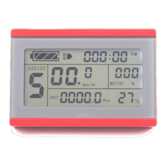
Page 8: Display Content
The display content is shown as follow. Button Definition KT-LCD3 meter adopts the structural form with part design between the main part and operating buttons. There are three keys on the operating panel of button box, which are icons of... -
Page 9: Display Interface
ELECTRIC BICYCLE METER KT—LCD3 Product User Manual meter for five minutes, the meter will automatically shut down, and the power supply of the electric vehicle will be powered off. In power off mode, the power consumption of the meter and controller is zero. ○... -
Page 10: Display 2
ELECTRIC BICYCLE METER KT—LCD3 Product User Manual Motor Operation Power Environment Temperature Backlights and Headlights Status Brake Status Cruise Function (CRUISE) Motor Running Temperature Display 2: In display 1, hold button (SW) shortly to enter display 2. Display 2 The followings are shown on display 2: Total Trip Time (TTM) Total Trip Distance (ODO) - 9 -... - Page 11 ELECTRIC BICYCLE METER KT—LCD3 Product User Manual Single Average Speed (AVS) Motor Operating Temperature In the riding mode after 5 seconds, display 2 automatically returns to display 1. In display 1, the original motor power is replaced by motor running temperature as is shown in Figure.
-
Page 12: Display Of Turned On Handlebar
ELECTRIC BICYCLE METER KT—LCD3 Product User Manual In display 3, hold button (SW) shortly again to enter display 1. In each display interface, if you hold button (SW) long, the meter will be powered-off together with that of the controller. ○... -
Page 13: Pas Ratio (Or Handlebar) Gear Switch
ELECTRIC BICYCLE METER KT—LCD3 Product User Manual ○ PAS Ratio (or Handlebar) Gear Switch Under normal operation, hold button (UP) or button (DOWN) to switch the power assist ratio (or handlebar) gear (ASSIST), changing motor output power. Switching range is 1-5 gear (this can also be configured according to the customer requirements), gear 1 is for the lowest power, and gear 5 is for the highest power. -
Page 14: Cruise Function
ELECTRIC BICYCLE METER KT—LCD3 Product User Manual ○ Cruise Function When C7 parameter setting is 1 (see C parameter setting), the meter turns on cruise function, hold button (DOWN) long to enter the cruise status when the vehicle speed is more than 7 km/h, and the cruise function logo (CRUISE) lights. Brake or hold any button to revoke cruise function. -
Page 15: Motor Power And Temperature
ELECTRIC BICYCLE METER KT—LCD3 Product User Manual When the controller is power off due to voltage shortage, the power display frame flashes, indicating the vehicle has been in voltage shortage and waiting for shutdown currently. Voltage shortage flashes Battery capacity indicator ○... -
Page 16: Environment Temperature
ELECTRIC BICYCLE METER KT—LCD3 Product User Manual Motor operating temperature When the motor operating temperature exceeds the warning value, temperature display flashes to alarm, meanwhile the motor controller will offer the appropriate protection to motor. ○ Environment Temperature After startup, the environment temperature for using meter will be displayed in environment temperature display column. -
Page 17: Automatic Prompt Interface
Under any interface, when the motor operating temperature exceeds the warning value, the motor operating temperature display flashes to alarm, meanwhile, the controller will offer the appropriate protection to motor. User Setting Project KT-LCD3 meter user setting project: ◇ General project setting ◇... -
Page 18: General Project Setting
ELECTRIC BICYCLE METER KT—LCD3 Product User Manual General Project Setting ○ Maximum Trip Speed Under power off status, hold button long (SW), the meter is turned on. Within 5 seconds after boot-up, hold button (UP) and button (DOWN) simultaneously for about 2 seconds, the first is to enter the maximum riding speed setting interface, then the speed display column flashes. -
Page 19: Metric And Imperial Units
ELECTRIC BICYCLE METER KT—LCD3 Product User Manual Setting Interface of Wheel Diameter Under the wheel diameter setting interface, if there’s no button operation on the meter for more than 1 minute, and then the meter will automatically return to display 1, and the original set values will be saved. -
Page 20: Exit General Project Setting
ELECTRIC BICYCLE METER KT—LCD3 Product User Manual on the meter for more than 1 minute, and then the meter will automatically return to display 1, and the original set units will be saved. After finishing the metric/imperial units setting, hold button shortly (SW) to save the current set values, and then speed and mileage units stop flashing. -
Page 21: P2 Wheel Speed Pulse Signal Setting Mode
ELECTRIC BICYCLE METER KT—LCD3 Product User Manual P1 parameter setting interface Under P1 parameter setting interface, if there’s no button operation on the meter for more than 1 minute, and then the meter will automatically return to display 1, and the original set parameter will be saved. After finishing P1 parameter setting, hold button shortly to save the current set values and enter P2 parameter setting interface. -
Page 22: P3 Power Assist Control Mode
ELECTRIC BICYCLE METER KT—LCD3 Product User Manual After finishing P2 parameter setting, hold button (SW) shortly to save the current set values and enter P3 parameter setting interface. Please Note:when P2 parameter is set to be 0, for the built-in clutch motor, there will be the following defects, when the internal motor rotors stop or the internal rotor speed is lower than the outer rotor speed, then the speed displayed on the meter is inaccurate! ○... -
Page 23: P5 Power Monitoring Mode
ELECTRIC BICYCLE METER KT—LCD3 Product User Manual P4 parameter setting interface P4 is handlebar startup mode. When P4 setting is 1, indicating the handlebar is under "non-zero startup" mode, namely, the handlebar can be effective only after startup the foot power assist. When P4 setting is 0, indicating the handlebar is under "zero startup" mode, the motor can be startup by the handlebar directly. -
Page 24: Exit P Parameter Setting
ELECTRIC BICYCLE METER KT—LCD3 Product User Manual ○ Exit P Parameter Setting Among the five P parameter settings, when each parameter setting is completed, if held button (SW) long for about 2 seconds, all can exit the setting environment and return to display 1, meanwhile, the current set parameters would be saved. -
Page 25: C2 Motor Phase Classification Coding Mode
ELECTRIC BICYCLE METER KT—LCD3 Product User Manual Lowest Lowest Higher Higher Forward 8 Signal Standard Reverse 10 Signal Standard Lower Lower Highest Highest Forward 10 Signal Higher Reverse 12 Signal Higher Standard Standard After finishing C1 parameter setting, hold button (SW) shortly to save the current set values and enter C2 parameter setting interface. -
Page 26: C3 Power Assist Ratio Gear Initialization Mode
ELECTRIC BICYCLE METER KT—LCD3 Product User Manual ○ C3 Power Assist Ratio Gear Initialization Mode Enter C3 parameter setting interface after C2 parameter setting is finished, C3 parameter column flashes. C3 parameter setting interface C3 is initialization mode of power assist ratio gear. The setting range is 0-6 (gear), hold button (UP) or button (DOWN) for selection. -
Page 27: C5 Controller Maximum Current Adjustment Mode
ELECTRIC BICYCLE METER KT—LCD3 Product User Manual C4 value Handlebar startup mode P4=0 Handlebar startup mode P4=1 zero startup handlebar Non-zero startup handlebar Zero startup, handlebar speed limit is Before power assist, the handlebar speed limit is 6Km/h 6Km/h, after power assist, handlebar is full speed. Zero startup, handlebar speed limit is Non-zero startup, handlebar is specified speed specified... -
Page 28: C6 Backlight Brightness Adjustment Mode
ELECTRIC BICYCLE METER KT—LCD3 Product User Manual Undefined Undefined Maximum current value÷2.00 Maximum current value÷1.50 Maximum current value÷1.33 Maximum current value÷1.25 Maximum current value÷1.20 Maximum current value÷1.15 Maximum current value÷1.10 Maximum current value When C5 setting is 10, maximum current value is controller maximum operating current value (ie, limit current value);... -
Page 29: C7 Cruise Function Setting Mode
ELECTRIC BICYCLE METER KT—LCD3 Product User Manual C6 value Backlight brightness Dimmest Darker Standard Brighter Brightest After finishing C6 parameter setting, hold button (SW) shortly to save the current set values and enter C7 parameter setting interface. ○ C7 Cruise Function Setting Mode Enter C7 parameter setting interface after C6 parameter setting is finished, C7 parameter column flashes. -
Page 30: C9 Power-On Password Setting Mode
ELECTRIC BICYCLE METER KT—LCD3 Product User Manual parameter column flashes. C8 parameter setting interface C8 is motor operating temperature display mode. The setting range is 0 or 1, hold button (UP) or button (DOWN) shortly for selection. C8 parameter definition table: C8 value Motor operating temperature Function off... -
Page 31: C10 Automatic Restore Default Setting Mode
ELECTRIC BICYCLE METER KT—LCD3 Product User Manual button (UP) or button (DOWN) shortly for selection. C9 parameter definition table: C9 value Startup password setting Function off Function on When C9 setting is 1, hold button (SW) shortly, indicating that the password function is startup, and then enter the password settings interface, three password setting columns flash. -
Page 32: C11 Attribute Selection Mode
ELECTRIC BICYCLE METER KT—LCD3 Product User Manual C10 parameter setting interface C10 is automatic restore default settings mode. The default is n, and the setting can be n, or y, hold button (UP) or button (DOWN) shortly for selection. C10 parameter definition table: C10 value Restore default setting Function off... -
Page 33: C12 Controller Minimum Voltage Adjustment Mode
ELECTRIC BICYCLE METER KT—LCD3 Product User Manual (UP) or button (DOWN) shortly for selection. C11 parameter definition table: Meter Attribute value Meter uses LCD3 new version of communication protocol, it is compatible LCD1 and LCD2. Meter uses LCD1 and LCD2 old version communication protocol, it is not compatible LCD3. - Page 34 ELECTRIC BICYCLE METER KT—LCD3 Product User Manual C12 parameter setting interface C12 is controller minimum operating voltage adjustment mode (tiny adjustment of voltage shortage). The default value is 4, and the setting range is 0-7, hold button (UP) or button (DOWN) shortly for selection. C12 parameter definition table:...
-
Page 35: C13 Abs Brakes Of The Controller And Parameters Of Anti-Charge Control
ELECTRIC BICYCLE METER KT—LCD3 Product User Manual After finishing C12 parameter setting, hold button (SW) shortly to save the current set values and enter C13 parameter setting interface. ○ C13 ABS brakes of the controller and parameters of anti-charge control Enter into C13 parameter setting interface, C13 parameter bar flashes. -
Page 36: C14 Power-Assist Tuning Parameters
1 minute, and then the meter will automatically return to display 1, and the original set parameters will be saved. Parameter Copy Set parameters (include general project parameter, P parameter and C parameter) of all KT-LCD3 meter produced by our company according to requirements, and set the meter - 35 -... - Page 37 ELECTRIC BICYCLE METER KT—LCD3 Product User Manual to be a data source according to the method of "C11meter attribute selection mode". Use special wiring cables to properly wire to LCD3 meter needs to be copied according to the diagram. Meter parameter copy wiring diagram Special wiring cable Turn on meter power supply of data source.
-
Page 38: User Setting Note
ELECTRIC BICYCLE METER KT—LCD3 Product User Manual Interface of finishing parameter copy Both C9 power-on password and C11 meter attributes can’t be copied. Please note: Besides, LCD3 meter can only copy parameter of the same meter model. User Setting Note After entering the user setting environment, if there’s no button operation on the data for more than 1 minute, the meter will automatically return to display1, and the new set parameters won’t be saved.
Need help?
Do you have a question about the KT-LCD3 and is the answer not in the manual?
Questions and answers