
Summary of Contents for MUTHIANI SECURITY SYSTEMS VT1000
- Page 1 User Manual of VT1000 GPS Vehicle Tracker User Manual (Model: VT1000) Please Read Carefully Before Operation - 1 -...
- Page 2 User Manual of VT1000 - 2 -...
-
Page 3: Table Of Contents
5.1 Install SIM Card--------------------------------------------------------------------------------------6 5.2 Charging-----------------------------------------------------------------------------------------------6 5.3 LED indications---------------------------------------------------------------------------------------6 6. Connect the tracker VT1000 to GPRS01 Web Server Platform-------------------------------------7 Optional 1: Configure by Computer to set GPS tracker online--------------------------------------7 Optional 2: SMS Commands to set GPS tracker online---------------------------------------------12 Settings on Topshine GPRS01 Platform---------------------------------------------------------------13 ①... -
Page 4: Product Overview
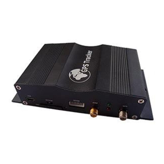
User Manual of VT1000 1. Product Overview VT1000 is a most advanced and high-cost effective GPS tracker, it is equipped with ARM9 high speedy microprocessor; using fully new and industrial grade modules, so VT1000 has high sensitivity and stable performance. Its functions also very powerful, it can supporting camera (location &driving information log on picture). -
Page 5: Specifications
User Manual of VT1000 * Harsh braking and harsh acceleration alarm * Suddenly acceleration/brake alert * Accident Alarm (optional) * Two way communication (Listen & Speak, need speaker support) (optional) * Oil leaking/Refuel Alarm (need fuel sensor support) (optional) * Accident alarm (need crash sensor support) (optional) * Support max 64G SD card store (optional) * Photo with location &... -
Page 6: First Use
Connect the device with external power like car battery, and turn on its power switch and it will do charging automatically. 5.3 LED indications Push the power switch to turn on/off VT1000 GPS LED (Red) Flashing (every 0.1 second) Initializing or back-up battery power is low Flashing (0.1 second on and 2.9 seconds off) -
Page 7: Connect The Tracker Vt1000 To Gprs01 Web Server Platform
User Manual of VT1000 6. Connect the tracker VT1000 to GPRS01 Web Server Platform Two Methods to set GPS tracker online: Configure by Computer or SMS Commands Optional 1: Configure by Computer to set GPS tracker online This part shows the basics of how to use the GPS tracker Parameter Editor. - Page 8 User Manual of VT1000 3. Open the GPS Tracker Parameter Editor ① Connect VT1000 with PC by the configuration cable ② Confirm VT1000is in the Power Off states ③ Double click GPS Tracker Parameter Editor.exe and Select the COM Port, following picture...
- Page 9 4. Click Start button to open the COM port, 5. Turn on VT1000 and it will connect with the Editor automatic, As soon as they connect successful, all the buttons are availability and the status bar will clue on’ Tracker Connect!’ , first click “Read”...
- Page 10 User Manual of VT1000 Instruction of parameter settings: Item Description GPRS Tick to enable GPRS function, select TCP or UDP mode Tracker ID Should be unique, in number, maximum 14 digits APN, Account, Put your local APN, APN username and password if necessary...
- Page 11 To set Mobile phone No. for SMS or Calling when Button Button C/IN3 C/Input 3 is triggered (alarm), it will call/SMS to this phone After write finished, click “Write” button to configure the VT1000’s Parameters. It will pop-up a mini window, as below pictures: - 11 -...
-
Page 12: Optional 2: Sms Commands To Set Gps Tracker Online
User Manual of VT1000 Please click “Read” button again, confirm your write parameter. When you finished the GPS Tracker Parameter Editor, then turn off the tracker, pull up the USB cable. Note: More about configure by computer, please check Appendix 1 Optional 2: SMS Commands to set GPS Tracker online ①... -
Page 13: Settings On Topshine Gprs01 Platform
Note: More GPRS01 Platform functions, please check manual of Operation Instruction of Topshine web-based tracking platform GPRS01. Next Step: Settings on Topshine GPRS01 Platform Turn on the tracker VT1000, when it normal working (find the GSM & GPS signal), ① Login Topshine GPRS01 Platform Website: www.global-track.net... -
Page 14: ② Vehicle Information Management
User Manual of VT1000 Note: Red box means the vehicle Online; Yellow box means the vehicle offline; Green box means the vehicle running. ② Vehicle Information Management Centralized management of all vehicles in the platform, the “Kind, GPRS ID, Plate No.” are mandatory terms, and the GPRS ID must be consistent with the tracker ID. -
Page 15: ④ Set Up Information For A New Vehicle
User Manual of VT1000 Click , then you can see picture below: Input ‘demo123’ in the blank of Group Name ,then group ‘demo123’ is ready as below: Click ④ Set up information for a new vehicle e.g. ‘Benz123’ Click the group name... - Page 16 User Manual of VT1000 2012060200001 Input the correct Kind, GPRS ID and Plate No. and Customize Mark etc. necessary information, click , then you can see group ‘demo123’ and vehicle ‘Benz123’ with tracker ID 20120602000010 have been set ready as below.
-
Page 17: Installation
User Manual of VT1000 7. Installation Please select experienced technicians to install this system. The installation should be carried in the working condition for this system. Install this system in a secret place. Prevent this system from dust and humidity. -
Page 18: Install I/O Cable
User Manual of VT1000 7.1 Install I/O Cable The I/O cable is a 16-pin cable including power, analog input, negative/positive input and output. PIN Number Color Description Input 1/SOS White wire Digital Input 1 (negative triggering), E.g. connect SOS panic... -
Page 19: Power/Gnd
User Manual of VT1000 Output 2 Yellow wire Output 3 Yellow wire E.g. connected with siren Output 4 Yellow wire E.g. Unlocked car door Output 5 Yellow wire E.g. Lock car door Blue 10 bits Resolution Analog Inputs. 0-6V DC Detection. It can be used to connect with temperature/fuel sensor etc. -
Page 20: Output
User Manual of VT1000 7.4 Output Example: Control fuel-cut 7.5 Install GPS/GSM Antenna Note: Do not shield or cover the GPS Antenna with any objects containing metal. 7.6 Install Camera (optional) (More specific details refer to Appendix 4) 7.7 Install Microphone and Speaker (optional) -
Page 21: Basic Sms Commands
User Manual of VT1000 8. Basic SMS Commands: Note: ①The default password is 000000, you should change the password when use the device. Change user’s password: W000000,001,****** (000000 is old password; ******is new password) ② Command Letter must be capitalized. -
Page 22: Set Receiving Physical Address Name Via Sms
User Manual of VT1000 8.2 Set receiving physical address name via SMS Description: To know specific address of device, send an SMS and you receive an SMS with its location physical address name. Command: W000000,111 Example: SMS send: W000000,111 Then you will receive an SMS as below picture:... -
Page 23: Enable Impact Alarm Function
When snap picture one time, it will store on SD card, it also upload the picture to platform at the same time. Note: More SMS Commands, please check Appendix 2: Command List 9. VT1000 Packing and Accessories Accessories IMAGE FUNCTION... -
Page 24: Vt1000 Optional Accessories
User Manual of VT1000 Relay 1 piece To cut-off/restore the power/fuel supply 16 PIN wire 1 piece Mainly used connect to the vehicle Microphone 1 piece Voice monitoring 10. Optional Accessories Optional Accessories Image Function Active RFID Kits anti-theft driver(student) -
Page 25: Troubleshooting
Unit is sleeping Cancel sleeping mode Wrong password in your SMS Insert the correct password The SIM in VT1000 has run out of credit Replace or top up the SIM card No SIM card Insert working SIM card. Check in phone that the SIM can send SMS messages. -
Page 26: Appendix 1 Configure By Computer
Battery is low Recharge the unit and the GSM will start working. Problem: SMS from VT1000 states ‘Last……’ Possible Cause: Resolution: Unit does not have clear view of the sky Move the antenna of the unit to a location where the sky is visible. -
Page 27: Appendix 2: Command List
Cut off Power Tick it to send alert when the external power be cut off Appendix 2: Command List Description Command Remarks Get current location W******,000 Get current location of VT1000 location W******,100 http://maps.google.com/map Google s?f=q&hl=en&q=22.542563 format via SMS ,114.077971&ie=UTF8&z= 16&iwloc=addr&om=1... - Page 28 =08, 2000m Extend Settings W******,008,ABCDEF A=0, disable position report function GHIJ### when a call is made to VT1000 A=1, enable position report function to get position SMS by Calling VT1000 I=0, disable power failure alert I=1, enable power failure alert...
- Page 29 ‘0’ is needed to be stuffed if no value available; 3. Send W******,017 or W******,117 without data to disable this function. Presetting by SMS for GPRS tracking Set ID for VT1000 by SMS W******,010,ID Tracker ID must be less than 14 digits Set APN by SMS...
- Page 30 Example: activated by an SMS or an If XX=10, VT1000 will enter incoming call) power saving mode in 10 minutes after it is immobile. Set phone number for...
-
Page 31: Appendix 3: How To Use Camera
User Manual of VT1000 clear/reset odometer W******,046 To clear and reset odometer function information to zero. function receiving W******,111 This function need support of location physical address name GPRS01 SMS01 via SMS tracking platform, address SMS will be received in text format. - Page 32 User Manual of VT1000 Configure means snap, E=0 means no action SMS for the F: Snap or not when over speed alarm triggered, W<password>,108,ABCDEFGHIJ### extended F=1 means snap, F=0 means no action photoing Example: W000000,108,1000000000### G: Snap or not when movement alarm triggered,...
- Page 33 User Manual of VT1000 2.3 On the platform applications Into our GPS Tracking Platform: http;//www.global-track.net , (following picture P1),login interface,(following picture P2) Select your device, such as instructed 1; it will display your car’s the logo on the map(instructed). Put the mouse on the logo, It will automatically pop up frame (instructed 3),you can click the ”Take Photo”...
-
Page 34: Appendix 4: Configure And Use Of Rfid Function
User Manual of VT1000 Appendix 4: Configure and use of RFID function RFID Reader RFID Tag 1. Install RFID as following: 2. How to use 2.1 SMS Commands 2.1.1 Firstly, enable the RFID: (1) Enable the RFID function:W000000,062,1 (2) Disable the RFID function: W000000,062,0 (3) The system default is RFID function enabled. - Page 35 User Manual of VT1000 RFID function, and if send the enable SMS command the RFID function will be restored. 2.1.4 Judge if need to cut off oil/fuel supply when the ignition alert occurs to stop engine start. Enable function of cutting off oil-way when illegally ignite under ARM status SMS command: W<password>,061,1...
- Page 36 User Manual of VT1000 several rings and hang off automatically, indicating the vehicle be armed. 4.5 If alert be triggered, the siren will sound for 10 seconds and shut or immediately shut when disarm action is detected. 4.6 If illegal ignition be detected and oil/fuel supply cut off enabled, then the oil/fuel supply will be cut off, and it will be immediately restored as soon as disarm action be detected.
-
Page 37: Appendix 5: Fuel Sensor Installation And Function
User Manual of VT1000 When finished, please press “save” button. Once again into the main interface, select the little red box, you will see the tracker location. Such as following picture: Appendix 5: Fuel Sensor Installation and Function 1. Installation instruction 1.1 Installation flow chart:... - Page 38 User Manual of VT1000 1.2 Operation procedures: 1.2.1 Find the position Generally installed in the middle of the fuel tank, to avoid the original fuel floater 1.2.2 Clean the oil stain on the installation position Clean the oil stain on the installation position 1.2.3 Holing...
- Page 39 User Manual of VT1000 Pistal Drill Hole saw Hexagon self tapping screw Extension cable of Fuel sensor: it’s better wiring along the fuel tank, generally for a big vehicle, 9~10 m cable is enough and 5~8 m for a small vehicle; choose the 3-core, 0.75mm2 cable.
- Page 40 User Manual of VT1000 Picture 1 2.2.2. Like picture 2 (1) Fill it up with fuel/oil in fuel tank. Let the tracker working. Then track the fuel(L) on platform: For example: the fuel(L) display: 603, this is Max Fuel, please write into “Max Fuel”.
- Page 41 User Manual of VT1000 4. Click “Save”. Finish. 2.3 Select your device, such as instructed 1; it will display your car’s the current oil/Fuel (L) (instructed2). 2.4 If you want to see the history record chart. Please click “Report Centre”(instructed 3), then the Report interface will pop up;...
- Page 42 User Manual of VT1000 it will display “Fuel Line” chart. You also can check History Report: - 42 -...
Need help?
Do you have a question about the VT1000 and is the answer not in the manual?
Questions and answers