
Related Manuals for Alto Betaverb

Summary of Contents for Alto Betaverb
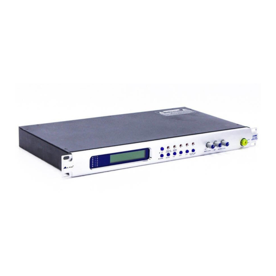
- Page 1 User's Manual βVERB β 24×32 BIT DIGITAL EFFECTS www.altoproaudio.com Version 2.3 September 2005 English English...
- Page 2 ˙ SAFETY RELATED SYMBOLS Fuse To prevent fire and damage to the product, use only the recommended fuse type as indicated in this CAUTION manual. Do not short-circuit the fuse holder. Before RISK OF ELECTRIC SHOCK DO NOT OPEN replacing the fuse, make sure that the product is OFF and disconnected from the AC outlet.
- Page 3 PREFACE Dear Customer: Thanks for choosing ▲LTO βVERB and thanks for choosing the one of results of the ▲LTO AUDIO TEAM job and researches. For our ▲LTO AUDIO TEAM, music and sound are more than a job...are first of all passion and let us say...our obsession! We have been designing professional audio products for a long time in cooperation with some of the major brands in the world in the audio field.
-
Page 4: Table Of Contents
TABLE OF CONTENTS 1. INTRODUCTION ................................... 4 2. FEATURE LIST ..................................4 3. FRONT AND BACK PANELS DESCRIPTION ......................4 3.1 Control Panel (Front Panel) a. Program and Variation Selections b. Analog Levels c. LED and Illuminated Power Switch 3.2 Analog Connections (Back Panel) a. -
Page 5: Introduction
1. INTRODUCTION Purchasing ▲LTO βVERB, you purchased a very powerful effect processor, easy to use and contained in a very efficient rack package. ▲LTO βVERB is divided in 9 effects algorithms and for each of them there are several factory presets so to reach totally 64 factory presets that can be used as starting point to create 64 customer's presets storable into 64 available memory locations. -
Page 6: Analog Levels
b. Analog levels - Analog Input Level Potentiometer (15): The input level control sets the main input gain, before the signal reaches the input bus. It controls both the Input1 and Input2 levels simultaneously. - Dry/Wet Mix Potentiometer for Analog Dry/Wet Mixing (16): This potentiometer represents one of the most powerful features of βVERB. -
Page 7: Power Up Setting
b. Power Up Setting After making your connections, turn on the system power using this procedure: Before turning on the βVERB power, check if: ˙All connections been have made correctly. ˙The volume controls of the amplifier or mixer are turned down. Insert the Power plug into the POWER input on the rear panel of the βVERB and plug the power cord into an AC outlet. - Page 8 ˙ Set manually the MONO ON/OFF switch to position ON. Connect one audio cable to the INPUT 2 of the MONO. βVERB from a mono source, and one or two other audio cables from the OUTPUT 1 and OUTPUT 2 of the βVERB to a mono/stereo amplification system or one/two mixer inputs.
-
Page 9: Operational Overview
Sending signal to the βVERB is only half of the process. With a mixing console, the output of the βVERB must go back to the mixer and turned up in the mix before to be able to hear it. Depending from the mixer, there are two options for returning the effected signal to the mix: ˙connecting to dedicated aux return inputs, or ˙connecting to channel inputs. - Page 10 Utility Button(13): To access the UTILITY Menu it's necessary to push the UTILITY Button (13). If the βVERB is already working on Utility Menu (Utility LED (4) = ON) each further use of the button will have no effect. Using the Utility Menu is possible to access the following functions: Load Preset: this function allows the loading of one of the 128 available presets, where the first 64 presets (1, 64), are factory presets, and the presets from 65 to 128 are the User's configurable presets and all not initia- lized (Empty) at βVERB selling time.
-
Page 11: Algorithms Descriptions
When Digital Mix ON/OFF is on, the analog mix potentiometer must be positioned on fully Wet. It is possible to save preset including digital direct sound. When recalled, if the Digital Mix ON/OFF function is on, the preset will have the previously chosen "%dir" and "%eff". If the Digital Mix ON/OFF is off, the recalled preset will have only the Wet full percentage. -
Page 12: Modulations
5.2 Modulations a. Tremolo Tremolo is an amplitude modulation of the signal. It is useful for adding warmth and life to standing electric piano or guitar's chords. Amplitude Multiplier Modulated bv Ramo / Sin LFO Tremolo- This program provides an amplitude modulation of the input signal and is normally used as "WET" effect without adding direct sound or adding a few percentage of it, so to avoid the direct sound to cover the amplitude modulation. -
Page 13: Delay
Amp Mod Cyl % Input Var delay line LP F LFO Sin LFO Sin LFO Sin LFO Sin Var delay line HP F Amp Mod Horn % 5.3 Delay Delay effect is a single echo repetition where the repetitions occur after a certain "delay time" and where the number of repetitions depend on a "decay time"... - Page 14 Time Right: 0/995 ms step 5 ms. Decay Left: min-max in 127 steps.Decay Right: min-max in 127 steps.Switchable effect high pass filter 50Hz/1 kHz step 1/3 oct. Switchable effect low pass filter 1 kHz/16 kHz step 1/3 oct. Link L+R: on/off. Percentage of effect : min-max in 127 steps.
- Page 15 Flanger Switchable high damp 1 kHz/16 kHz step 1/3 oct. Switchable low damp 50 Hz/1 kHz step 1/3 oct. Rate Left: min-max in 128 steps. Rate Right: min-max in 128 steps. Depth Left: min-max in 240 steps. Depth Right: min-max in 240 steps. Decay Left: min-max in 127 steps.
-
Page 16: Factory Presets Program Chart
5.5 Factory Presets Program Chart ROOM-REVERB Room 1 Room 2 Room 3 Room 4 Room 5 Room 6 Room 7 Room 8 Low Pass [Hz] Bypass Bypass Bypass Bypass Bypass Bypass Bypass Bypass H Damp [Hz] 12500 2500 12500 12500 12500 12500 12500... - Page 17 REVERSE Short G Long G Short R Long R Time [ms] PreDelay [ms] Density HP Eff [Hz] LP Eff [Hz] 6300 6300 6300 6300 Reverse Mode Gated Gated Linear Gated % Vol Eff % Vol Dir STEREO DELAY 100 ms 300 ms 400 ms M 100...
- Page 18 CHORUS Sin 1 Sin 2 Sin 3 Sin 4 Ramp 1 Ramp 2 Ramp 3 Ramp 4 H Damp [Hz] 8000 8000 8000 8000 8000 8000 8000 8000 L Damp [Hz] Rate L Rate R Depth L Depth R HP Eff [Hz] LP Eff [Hz] 6300 6300...
- Page 19 LESLIE Slow 1 Slow 2 Fast 1 Fast 2 LP Cyl [Hz] 2000 2000 2000 2000 HP Horn [Hz] 1600 1600 1600 1600 Rate Cyl Rate Horn Depth Cyl Depth Horn M Amp Cyl M Amp Horn Vol Cyl Vol Horn % Vol Eff % Vol Dir UTILITY MENU...
- Page 20 Reverb Effect - EDIT MENU Start Up/Down Enter/Esc Low Pass Input 1KHz,..,16KHz,Bypass; step 1/3 oct 1KHz,..,16KHz,Bypass; step 1/3 oct H Damp L Damp Bypass,50Hz,..,1KHz; step 1/3 oct PreDlelay Riv 0,...,254 ms step 2ms PreDlelay ER 0,...,254 ms step 2ms PreDlelay FR 0,...,254 ms step 2ms Diffusion 0,...,127;...
- Page 21 Reverse Effect - EDIT MENU init Up/Down Enter/Esc Time 36,...,636 ms step 3ms PreDelay 0,...,254 ms step 2ms Density 0,...,127; Min,...,Max High Pass Eff. Bypass,50Hz,...,1KHz; step 1/3 oct Low Pass Eff. 1KHz,...,16KHz,Bypass; step 1/3 oct Linear, Exp, Gated Reverse Mode % Volume Eff.
- Page 22 Stereo Delay Effect - EDIT MENU init Up/Down Enter/Esc Low Pass Input 1KHz,...,16KHz,Bypass; step 1/3 oct 1KHz,...,16KHz,Bypass; step 1/3 oct H Damp Bypass,50Hz,...,1KHz; step 1/3 oct L Damp 0,...,995 ms step 5ms Time R Time L 0,...,995 ms step 5ms Decay L 0,...,127;...
- Page 23 PingPong Delay Effect - EDIT MENU init Up/Down Enter/Esc Low Pass Input 1KHz,...,16KHz,Bypass; step 1/3 oct 1KHz,...,16KHz,Bypass; step 1/3 oct H Damp Bypass,50Hz,...,1KHz; step 1/3 oct L Damp 0,...,995 ms step 5ms Time Decay 0,...,127; Min,...,Max High Pass Eff. 1KHz,...,16KHz,Bypass; step 1/3 oct Bypass,50Hz,...,1KHz;...
- Page 24 Multi Delay Effect - EDIT MENU Up/Down init Up/Down Enter/Esc 1KHz,...,16KHz,Bypass; step 1/3 oct Low Pass Input H Damp 1KHz,...,16KHz,Bypass; step 1/3 oct L Damp Bypass,50Hz,...,1KHz; step 1/3 oct Time 1 0,...,995 ms step 5ms Time 2 0,...,995 ms step 5ms 0,...,995 ms step 5ms Time 3 Decay 1...
- Page 25 Chorus Effect - EDIT MENU Up/Down init Up/Down Enter/Esc H Damp 1KHz,...,16KHz,Bypass; step 1/3 oct L Damp Bypass,50Hz,...,1KHz; step 1/3 oct Rate L 0,...,128; Min,...,Max Rate R 0,...,128; Min,...,Max Depth L 0,...,240; Min,...,Max Depth R 0,...,240; Min,...,Max High Pass Eff. Bypass,50Hz,...,1KHz;...
- Page 26 Flange Effect - EDIT MENU Up/Down init Up/Down Enter/Esc 1KHz,...,16KHz,Bypass; step 1/3 oct H Damp Bypass,50Hz,...,1KHz; step 1/3 oct L Damp 0,...,128; Min,...,Max Rate L Rate R 0,...,128; Min,...,Max 0,...,240; Min,...,Max Depth L Depth R 0,...,240; Min,...,Max 0,...,127; Min,...,Max Decay L 0,...,127;...
- Page 27 Tremolo Effect - EDIT MENU Up/Down init Up/Down Enter/Esc 1KHz,...,16KHz,Bypass; step 1/3 oct H Damp L Damp Bypass,50Hz,...,1KHz; step 1/3 oct Rate L 0,...,128; Min,...,Max Rate R 0,...,128; Min,...,Max Depth L 0,...,240; Min,...,Max Depth R 0,...,240; Min,...,Max High Pass Eff. Bypass,50Hz,...,1KHz;...
- Page 28 Leslie Effect - EDIT MENU Start Up/Down Enter/Esc Low Pass Cyl 50Hz ,..,16KHz,Bypass; step 1/3 oct High Pass Horn Bypass,50Hz,.. ,16KHz; step 1/3 oct Rate Cyl 0,...,128; Min ,..,Max 0,...,128; Min ,..,Max Rate Horn Depth Cyl 0,...,240; Min ,..,Max Depth Horn 0,...,240;...
- Page 29 Effect & Parameter St_Dly Pp_Dly Mt_Dly Flanger Reverb Revers Chorus Tremolo Leslie Low Pass Time Low Pass Low Pass Low Pass H-Damp H-Damp H-Damp Low Pass Input Input Input Input H-Damp PreDelay H-Damp H-Damp H-Damp L-Damp L-Damp L-Damp High Pass Horn L-Damp Density...
- Page 30 MIDI Change Preset MIDI 1 Byte - PROGRAM CHANGE MIDI 2 Byte - 0,...,127 Legend MIDI 2 byte Preset 0,...,7 Reverb - Room Preset Custom Effect 1 8,...,15 Reverb - Hall Preset Custom Effect 1 16,...,23 Reverb - Plate Preset Custom Effect 1 24,...,27 Reverse Preset Custom Effect 2...
- Page 31 Legend MIDI 2 byte Reverse MIDI 3 byte Time 0,...,100 0 / 100ms; Step 1ms PreDelay 0,...,127 0 / 254 ms; Step 2ms Density 0,...,127 0,...,127 High Pass eff 0,...,14 Bypass,50Hz,..,1KHz; step 1/3 oct Low Pass eff 0,...,13 1KHz,..,16KHz,Bypass; step 1/3 oct Revers Mode 0,1,2 Gated, Linear, Exp...
- Page 32 Legend 2 byte Chorus 3 byte H-Damp 0,... ,13 1KHz,..,16KHz,Bypass; step 1/3 oct 0,...,14 L-Damp Bypass,50Hz,..,1KHz; step 1/3 oct 0,...,128 0,...,128 Rate L 0,...,128 0,...,128 Rate R 0,...,240 0,...,240 Depth L Depth R 0,...,240 0,...,240 Bypass,50Hz,..,1KHz; step 1/3 oct High Pass eff 0,..14 1KHz,..,16KHz,Bypass;...
-
Page 33: Technical Specifications
6. TECHNICAL SPECIFICATIONS Analog Input section Inputs Analog variable gain, 1/4" TRS and XLR-F Input Impedance 44 kOhms Max. input Level 15 dBu (4.4V RMS) Sensitivity -22 dBu (63mV RMS) Analog Output section Outputs Analog variable gain, 1/4" TRS and XLR-M Output Impedance <150 Ohms Max. -
Page 34: Warranty
7. WARRANTY 1. WARRANTY REGISTRATION CARD To obtain Warranty Service, the buyer should first fill out and return the enclosed Warranty Registration Card within 10 days of the Purchase Date. All the information presented in this Warranty Registration Card gives the manufacturer a better understanding of the sales status, so as to purport a more effective and efficient after-sales warranty service. - Page 35 No. 1, Lane 17, Sec. 2, Han Shi West Road, Taichung 40151 Taiwan http://www.altoproaudio.com Tel: 886-4-22313737 email: alto@altoproaudio.com Fax: 886-4-22346757 All rights reserved to ALTO. All features and content might be changed without prior notice. Any photocopy, translation, or reproduction of part of this manual without written permission is forbidden. Copyright...
Need help?
Do you have a question about the Betaverb and is the answer not in the manual?
Questions and answers