Table of Contents

Related Manuals for EVEKTOR-AEROTECHNIK EV-97 Eurostar SL


Summary of Contents for EVEKTOR-AEROTECHNIK EV-97 Eurostar SL
- Page 1 EVEKTOR – AEROTECHNIK a.s. tel.: +420 572 537 111 Letecka 1384 fax: +420 572 537 900 686 04 Kunovice marketing@evektor.cz CZECH REPUBLIC www.evektor.cz AIRPLANE TECHNICAL DESCRIPTION OPERATING, MAINTENANCE AND REPAIR MANUAL EV-97 Eurostar SL...
- Page 2 © EVEKTOR - AEROTECHNIK , 2008...
- Page 3 EVEKTOR – AEROTECHNIK a.s. Letecka 1384 686 04 Kunovice Czech Republic tel.: +420 572 537 111 fax: +420 572 537 900 EV-97 Eurostar SL Model: Serial Number: Registration: Owner: ........................................Document No.: Date of Issue: Revision: EV97SLNOEN 02/2008...
- Page 4 The manufacturer invites suggestions and reminders concerning this manual, and appreciates proposals for corrections. We invite you to share your experiences with us during operation of your...
-
Page 5: General
1. GENERAL Document No.: Date of Issue: Revision: EV97SLNOEN 02/2008... -
Page 6: Information Source
Information source Airplane manufacturer issues information and mandatory bulletins to ensure continued airworthiness of the airplane. The bulletins are provided to all known owners and dealers of the EV-97 Eurostar SL airplane. All bulletins may be downloaded from: http://www.evektor.cz/at/en/index.htm#sportstar You can also contact us via mail, telephone, fax or e-mail mentioned on the title page. -
Page 7: Record Of Revisions
Record of revisions Any revisions or amendments to this manual shall be issued in the form of bulletins with attached new pages. It is in the interests of every user to enter such revision into the table of revisions and to replace the existing page by the new one. -
Page 8: List Of Effective
List of Effective Pages Sec. Page Date Sec. Page Date Sec. Page Date Sec. Page Date Sec. Page Date 2-27 02/2008 02/2008 02/2008 02/2008 2-28 02/2008 02/2008 02/2008 02/2008 2-29 02/2008 02/2008 02/2008 02/2008 02/2008 2-30 02/2008 02/2008 02/2008 02/2008 02/2008 2-31 02/2008... -
Page 9: Table Of Contents
Contents GENERAL ..........................1-1 ........................1-2 NFORMATION SOURCE ........................1-3 ECORD OF REVISIONS ......................1-4 IST OF FFECTIVE AGES ..........................1-5 ONTENTS TECHNICAL DESCRIPTION ......................2-1 ....................2-2 ASIC AND GENERAL INFORMATION 2.1.1 Designation ..........................2-2 .......................2-3 ASIC TECHNICAL DATA 2.2.1 Airplane views ..........................2-3 2.2.2 Three-view drawing ........................2-4 2.2.3 Basic dimensions........................2-5 2.2.4... - Page 10 3.4.6 Trim tab deflections measurement..................3-20 ......................3-21 ERMISSIBLE OLERANCES C.G.................3-22 EIGHING THE AIRPLANE AND CALCULATION 3.6.1 Empty weight determination ....................3-22 3.6.2 Operating C.G. Range calculation ..................3-23 ........................3-24 ROUND HANDLING 3.7.1 Towing the airplane ........................3-24 3.7.2 Parking the airplane........................3-24 3.7.3 Tieing-Down...........................3-24 3.7.4 Jacking the airplane........................3-25 ........................3-25...
- Page 11 ........................5-3 ATERIALS USED 5.3.1 List of skin sheets........................5-3 ..........................5-4 KIN REPAIR 5.4.1 Riveting ............................5-5 ......................5-6 IBERGLASS PARTS REPAIRS 5.5.1 Damage classification.......................5-6 5.5.2 General ............................5-6 5.5.3 Parts of external appearance....................5-6 5.5.4 Structural parts.........................5-8 ...........................5-9 AINT REPAIRS 5.6.1 Safety rules ..........................5-9 5.6.2 Recommendation for paint repairs ....................5-9 5.6.3 Small damage ........................5-133...
- Page 12 Intentionally left blank Date of Issue: Revision: Document No.: 02/2008 EV97SLNOEN...
-
Page 13: Technical Description
2. TECHNICAL DESCRIPTION Document No.: Date of Issue: Revision: EV97SLNOEN 02/2008... -
Page 14: Basic And General Information
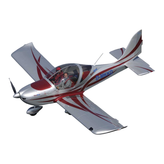
Basic and general information EV-97 Eurostar SL is a single engine, metal composite, low-wing monoplane of semimonocoque construction with two side-by side seats. The aircraft is equipped with fixed, tricycle landing gear. The standard powerplant consists of the four-cylinder, 4 stroke, ROTAX 912UL (80 hp) engine and the two blade, wooden, V 230 C fixed prop. -
Page 15: Basic Technical Data
Basic technical data 2.2.1 Airplane views Document No.: Date of Issue: Revision: EV97SLNOEN 02/2008... -
Page 16: Three-View Drawing
2.2.2 Three-view drawing Date of Issue: Revision: Document No.: 02/2008 EV97SLNOEN... -
Page 17: Basic Dimensions
2.2.3 Basic dimensions Wing span.............. 26.57 ft area ............105.92 sq ft 9.84 m MAC ...............4.10 ft 1.25 m (MTOW 992 lb, 450 kg) ....9.37 lbf/sq ft loading 45.7 kg/m (MTOW 1058 lb, 480 kg) .....9.99 lbf/sq ft 48,8 kg/m Aileron area ............2.26 sq ft 0.21 m... -
Page 18: Weight
2.2.4 Weight Empty weight (standard equipment) ..........646 lbs± 3% 293 kg ± 3% (Czech Rep., Germany..) ..... 992 lbs Maximum Take-off weight 450 kg (Slovak Republic, Canada)..1058 lbs 480 kg (Czech Rep., Germany..) ..... 992 lbs Maximum Landing weight 450 kg (Slovak Republic, Canada).. -
Page 19: Technical Description Of The Airplane
Technical description of the airplane 2.3.1 General EV-97 Eurostar SL airframe is of semi-monocoque metal composite construction formed with metal reinforcements, bulkheads and duralumin cover. Pop-rivets are used for joints and some non-supporting parts are made from fiberglass. 2.3.2 Fuselage The fuselage has a semi-monocoque construction formed with reinforcements and duralumin covers. -
Page 20: Horizontal Tail Unit
2.3.4 Horizontal tail unit The rectangular HTU consists of a stabilizer and elevator with a trim tab. The semi-monocoque construction of the HTU consists of duralumin ribs, spar and cover. The width of 8.2 ft (2.5 m) enables transport without dismantling. 2.3.4.1 Stabilizer The stabilizer is rectangular in shape and formed with a duralumin cover and ribs. -
Page 21: Landing Gear
2.3.6 Landing gear 2.3.6.1 General description The aircraft is equipped with fixed nosewheel landing gear. The nosewheel is steerable, but as an option, can be casterable, only. Fig. EV-97 Eurostar 1 - Steerable nosewheel 2 - Main landing gear 2.3.6.2 Main landing gear 2.3.6.2.1 Description The main landing gear consists of the left and right landing gear legs. - Page 22 2.3.6.3.2 Main landing gear layout MAIN LEG ATTACHMENT ANGLE REINFORCEMENT MAIN LEG ATTACHMENT MAIN LEG WHEEL WITH BRAKE SCREW 4x40 ÈSN 02 1781.04 MAIN LEG NUT M16x1.5 ÈSN 02 1412.24 WASHER SCREW 5x10 ÈSN 02 2150.01 FLIGHT DIRECTION Fig. Main leg attachment into fuselage Date of Issue: Revision: Document No.:...
- Page 23 2.3.6.3.3 Steerable nosewheel landing gear layout FUSELAGE FRAME SUSPENSION STOP NOSE WHEEL LEG RUBBER ROPE SUSPENSION FOOT PEDAL NOSE WHEEL 17 ° CONTROL ROD COTTER PIN 4x40 ÈSN 02 1781.04 NUT 765 155 WHEEL AXLE WASHER 765 478 WASHER E 54-04 21 NOSE WHEEL ASSEMBLY Document No.: Date of Issue:...
- Page 24 2.3.6.4 Auxiliary tail skid 2.3.6.4.1 Description The auxiliary tail skid is attached at the lower rear part of the fuselage and protects the aircraft from inadvertent damage during tail-down landing conditions. The tail skid is formed from composite material. Fig. Auxiliary tail skid Date of Issue: Revision: Document No.:...
- Page 25 2.3.6.5 Wheel brakes 2.3.6.5.1 Description Both wheels on the main landing gear are equipped with hydraulic disc brakes. The brake system consists of the brake pedals (pilot standard, co-pilot as an option), hydraulic brake master cylinders, plastic hoses, brake caliper with the hydraulic brake cylinder, brake pads and the brake disc which is bolted onto the inner part of the rim.
- Page 26 2.3.6.5.3 Brake system layout Parking brake ON: Step on both toe-brake pedals to raise pressure in the brake system and with the pedals pressed pull the parking brake lever up Parking brake OFF: release the parking brake lever down, step on and release the toe-brake pedals Note Parking brake should be used for short period parking.
- Page 27 2.3.6.6 Wheels 2.3.6.6.1 Description All the wheels consist of a two-part casting rim with a tire and tube. The main wheels are on an axle attached to the main gear leg, fastened by the nuts. 2.3.6.6.2 Main undercarriage wheel layout WHEEL WITH BRAKE SCREW 4x40 ÈSN 02 1781.04 MAIN LEG...
-
Page 28: Cockpit
The cockpit floor is covered with a removable carpet and the seats are also covered with a thin upholstery. The inerior cockpit sides are covered with padded panels containing pockets. The actual cockpit controls and instrument arrangement is described later. Fig.: Cockpit of the Ev-97 Eurostar SL Date of Issue: Revision: Document No.:... - Page 29 2.3.7.2 Cockpit controls The standard cockpit control arrangement is shown in the following figure. A detailed instrument panel is shown in par. 2.3.8.3. Fig. quadrant between the seats 1- flaps control lever, 2 - elevator trim tab control lever Document No.: Date of Issue: Revision: 2-17...
- Page 30 2.3.7.3 Cockpit canopy The bubble canopy consists of two parts. The front perspex portion can be tilted forward and is attached to a composite frame. The fixed rear portion is made of perspex. The canopy is attached to the nose section of the fuselage by two pins which make it possible for the canopy to be tilted forward.
-
Page 31: Equipment
2.3.8 Equipment 2.3.8.1 Seats and safety harness The plane has two side-by-side seats which are fixed and covered with upholstery, each equipped with seatbelts. Adjustable rudder pedals are optional. The seatbelts are attached alongside the seat and in the middle of the bulkhead behind the baggage compartment. The seatbelts are provided as four point safety belts. - Page 32 2.3.8.3 Instrument panel EV-97 Eurostar SL The following instrument panel is installed in the airplane, S/N (example) Date of Issue: Revision: Document No.: 2-20 02/2008 EV97SLNOEN...
-
Page 33: Avionics
2.3.9 Avionics EV-97 Eurostar SL The following instruments are installed in airplane, ……………….: (example) 2.3.9.1 Flight and navigation instruments 1 Airspeed indicator ....1 Altimeter ....... 1 Compass....... 1 Variometer ......1 Bank indicator ....... NOTE Refer to the Manuals supplied with above listed instruments for operation. -
Page 34: Additional Equipment
2.3.10 Additional equipment EV-97 Eurostar SL The following optional equipment is installed in the airplane, S/N Date of Issue: Revision: Document No.: 2-22 02/2008 EV97SLNOEN... - Page 35 Intentionally left blank Document No.: Date of Issue: Revision: 2-23 EV97SLNOEN 02/2008...
- Page 36 Intentionally left blank Date of Issue: Revision: Document No.: 2-24 02/2008 EV97SLNOEN...
-
Page 37: Control System
2.3.11 Control system 2.3.11.1 Longitudinal control system description The airplane is equipped with a classic dual control system. The elevator is controlled by a control stick, with connecting rods and arms. A control stick push/pull movement is transmitted, by a rod inside the quadrant between the seats to the elevator through a two-armed lever located underneath the baggage compartment floor cover. - Page 38 2.3.11.4 Flap control system description The wing flaps are controlled by a control lever in a changing gate. The lever push/pull movement is transferred to a longitudinal movement of a rod guided inside the quadrant between the seats. Then to an angular displacement of a two-armed lever welded onto a tube connecting left and right flap.
- Page 39 2.3.11.7 Longitudinal control system layout Document No.: Date of Issue: Revision: 2-27 EV97SLNOEN 02/2008...
- Page 40 2.3.11.7.1 Lateral control system layout Date of Issue: Revision: Document No.: 2-28 02/2008 EV97SLNOEN...
- Page 41 2.3.11.7.2 Electric aileron tab control system layout (optional) Document No.: Date of Issue: Revision: 2-29 EV97SLNOEN 02/2008...
- Page 42 2.3.11.8 Directional control system layout Date of Issue: Revision: Document No.: 2-30 02/2008 EV97SLNOEN...
- Page 43 2.3.11.9 Flap control system layout Document No.: Date of Issue: Revision: 2-31 EV97SLNOEN 02/2008...
- Page 44 2.3.11.10 Trim tab control system layout Date of Issue: Revision: Document No.: 2-32 02/2008 EV97SLNOEN...
- Page 45 2.3.11.10.1 Electric elevator trim tab control system layout (optional) Document No.: Date of Issue: Revision: 2-33 EV97SLNOEN 02/2008...
- Page 46 2.3.11.11 Nosewheel control system layout FRAME SYSTEM NOSE WHEEL LEG NUT M6 ÈSN 02 1413.44 WASHER 6 ÈSN 31 3282.11 CONTROL COTTER PIN 1.6x14 ÈSN 02 1781.05 TIGHTENING STRIP E (2:1) WASHER 6 ÈSN 31 3282.11 SCREW 6x25 ÈSN 02 1413.44 NUT M6 ÈSN 02 1413.44 COTTER PIN 1.6x14 ÈSN 02 1781.05 Date of Issue:...
-
Page 47: Powerplant
2.3.12 Powerplant 2.3.12.1 Brief description The standard powerplant consists of the four-cylinder, 4 stroke ROTAX 912UL version, (80 hp) engine and 2 blade, wooden, V 230 C fixed prop. The ROTAX 912ULS (100 hp) engine may be installed as option. The enine data is scanned by an analog instruments or by EMS (Engine Monitoring System) as an option. -
Page 48: C Ontents
2.3.12.2.2 Technical data ROTAX 912 engine is installed in the aircraft of S/N ROTAX 912UL ROTAX 912ULS Engine Model: Engine Manufacturer: Bombardier-Rotax GMBH 59.6 kW / 80 hp 73.5 kW / 100 hp Max Take-off: at 5800 rpm, max.5 min. at 5800 rpm, max.5 min. - Page 49 2.3.12.3 Propeller 2.3.12.3.1 Description The standard powerplant consists of the four-cylinder, 4 stroke ROTAX 912 (80 hp) engine and V 230 C prop. The V 230 C is a fixed, wooden, 2-blade propeller with leading edge protection. The prop is attached to the propeller hub with 6 bolts.
- Page 50 2.3.12.3.2 Propeller pitch adjustment Intentionally left blank. Date of Issue: Revision: Document No.: 2-38 02/2008 EV97SLNOEN...
- Page 51 2.3.12.4 The Engine Monitoring System (EMS) TL 3724 The Rotax 912 engine parameters are monitored by the Engine Monitoring System (EMS) TL 3724 (if installed). The following parameters are displayed on the EMS display: Engine speed Engine hours ...
- Page 52 If analog engine instruments are installed (instead of the EMS instrument) then the instruments limit indicators should show the following: Function Minimum Normal Caution Maximum Limit Operating Range Range (red line) (green arc) (yellow arc) (red line) Engine speed [RPM] 1400 1400-5500 5500-5800...
- Page 53 2.3.12.5 Engine mount 2.3.12.5.1 Description The engine mount is welded from chrome-molybdenum tubes and is attached to the firewall with 4 bolts. The bed is spring-mounted with four rubber silentblocks. Fig. Engine mount 1- bed, 2 - rubber silentblock 2.3.12.5.2 Engine mount diagram Document No.: Date of Issue: Revision:...
- Page 54 2.3.12.6 Engine cowlings 2.3.12.6.1 Description There are two fiberglass cowlings (upper and lower) attached to the engine mount which cover the engine. The interior sides of the cowlings are protected with fireproof paint, exterior sides are painted with aircraft paint. The upper cowling is connected to the lower cowling with quick-closing locks and is usually removed for preflight inspections.
-
Page 55: Fuel System
2.3.13 Fuel system 2.3.13.1 Fuel system description The standard fuel tank volume is 17.2 USGAL (65 liter). The tank is located behind the seat backrests. Fuel is pulled from the fuel tank through the fuel valve located inside the cockpit on the left-hand side, below the instrument panel. - Page 56 2.3.13.2 Standard fuel system layout Date of Issue: Revision: Document No.: 2-44 02/2008 EV97SLNOEN...
-
Page 57: Engine Lubrication System Scheme
2.3.13.3 Fuel tank draining The objective is to drain any water and/or contaminates in the fuel tank. Draining procedure: 1. Fully extend the flaps 2. Place a suitable bottle or transparent cup below the draining outlet hose (near the right-hand flap root) 3. -
Page 58: Cooling System Description
2.3.15 Cooling system description 2.3.15.1 Cooling system description The cooling system uses two forms of cooling. The cylinder heads are liquid cooled and the cylinders ram air cooled. The radiator is located in the front of the lower engine cowling. The coolant is forced through the radiator by a water pump, driven from the crankshaft to the cylinder heads. -
Page 59: Heating
2.3.16 Heating A cockpit heating system is optional. 2.3.16.1 Description One air hose leads the air to the heat exchanger in the exhaust system where the air is heated up, then it is led through the valve at the firewall to the mixing chamber in the cockpit floor. When the valve is closed, the air is led through the outlet air hose under the aircraft. -
Page 60: Ventilation
2.3.17 Ventilation 2.3.17.1 Description Ventilation is ensured by 2 eye–ball vents located on the left and right of the tip-up canopy frame. Vents are connected to the NACA scoops through tip-up canopy frame front flaps. Defrosting of windshield and sides ensured by hot air conducted from a cold/hot air mixing chamber on the firewall into the tip-up canopy frame and the through a row of holes onto the glass. -
Page 61: Wiring
2.3.18 Wiring 2.3.18.1 Wiring description The electric system is single-wire type with the negative side connected to the chassis. The power source is a single-phase generator integral to the engine. A 12V/16Ah maintenancefree battery is located on the firewall. The system is protected by the main circuit breaker (ACCU) 30 Amps. The circuits of the particular sections are guarded individually by circuit breakers. -
Page 62: Pitot-Static System
2.3.19 Pitot-static system 2.3.19.1 Pitot-static system description The Pitot-static tube, located under the left wing near the aileron root, provides both dynamic and static air pressure. Pressure distribution to individual instruments is done through flexible plastic hoses. Keep the system clear to ensure its correct function. Both hose systems (Dynamic and static) are equipped with dirt pockets. -
Page 63: Placards
2.3.20 Placards A new aircraft is equipped with placards supplied by the airplane manufacturer. These placards explain the purpose of controls, instruments, airspeed limits, weight limits, etc. Placards with supplemetal information such as a direction of handles are also supplied. The placards are usually attached to the appropriate instruments and controls. - Page 64 Intentionally left blank Date of Issue: Revision: Document No.: 2-52 02/2008 EV97SLNOEN...
-
Page 65: Operation
3. OPERATION Document No.: Date of Issue: Revision: EV97SLNOEN 02/2008... -
Page 66: Operation Outlines
Operation outlines EV-97 Eurostar SL During operation of the it is required to have in the following documentation in the plane: Airplane Technical Description, Operating, Maintenance and Repair Manual EV-97 Eurostar SL EV-97 Eurostar SL Airplane Flight Manual for ... -
Page 67: Wing
Airplane assembly 3.2.1 Wing 3.2.1.1 Wing assembly The wing assembly procedure for an aircraft not-equipped with the optional wing folding mechanism is the following (3 persons are needed to accomplish this task): 3.2.1.1.1 Necessary tools a hammer to move the wing suspension pins ... - Page 68 3.2.1.2 Wing disassembly 3.2.1.2.1 Necessary tools a hammer to tap the wing suspension pins out a screwdriver to unscrew the wing fillet connection screws wrenches to unscrew the rear wing suspension bolt nut a drift made from duralumin round or other suitable material (diameter 10-12 mm) to drive out the wing suspension pins 3.2.1.2.2 Wing-from-fuselage disassembly 1.
- Page 69 3.2.1.3 Wing folding The aircraft may be optionally adapted for wing folding possibility. The wing folding is convenient to reduce the parking area required in a hangar and to allow transportation on a suitable trailer. The wings may be folded in 15 minutes by 2 people. 3.2.1.3.1 Wing suspensions scheme Fig.
- Page 70 3.2.1.3.3 Wing folding procedure 1. Insert plastic O-ring onto right strut, secure by cotter pin. Insert the right strut into the hole provided in the rear right side of fuselage. Put the strut through the fuselage (the holes in fuselage sides are covered with spring loaded covers). see FIG.
- Page 71 3.2.1.3.4 Wing reassemble procedure 1. An assistant holds the wing tip 2. Another person removes the safety pin securing the wing on the wing rest hinge 3. The assistant removes the wing from the rest (using caution with the pitot-static tube under left wing) 4.
- Page 72 Date of Issue: Revision: Document No.: 02/2008 EV97SLNOEN...
- Page 73 Document No.: Date of Issue: Revision: EV97SLNOEN 02/2008...
-
Page 74: Horizontal Tail Unit
3.2.2 Horizontal tail unit 3.2.2.1 HTU-from-fuselage disassembly 1. Unscrew attachment bolts of HTU-fuselage fiberglass cover. 2. Disconnect the trim tab control cables (or electric wire when electric trim tab control is installed).. 3. Disconnect the elevator control rod. 4. Remove the safety pins securing the castle nuts on the bolts of the stabilizer rear suspensions. Screw off the nuts and remove the washers. -
Page 75: Vertical Tail Unit
3.2.3 Vertical tail unit 3.2.3.1 Assembly and Disassembly of the rudder 3.2.3.1.1 Necessary tools a wrench to tighten/remove the M5 nut 3.2.3.1.2 Rudder-from-fuselage disassembly 1. Disconnect the rudder control cables, attach the ends of the cables together to keep the cables from sliping inside the fuselage. -
Page 76: Landing Gear
3.2.4 Landing gear 3.2.4.1 Tire replacement 1. Support the aircraft to lift a wheel with punctured tire. Main wheel: It is recommended to support the aircraft near the main gear leg entry into the fuselage (a reinforced area) Nose wheel: a) Push the rear of the fuselage down and support the aircraft under the nosewheel leg-fuselage attachment or b) Load the fuselage rear near the fin (bags with a load) to lift the nosewheel above the ground... - Page 77 3.2.4.2 Assembly and disassembly of wheel pants An airplane may be equipped with the optional aerodynamic fiberglass wheel pants. 3.2.4.2.1 Main landing gear wheel pants The main wheel pant is attached with 8 screws to the main leg from the inner side and with 1 screw from outer...
- Page 78 3.2.4.3 Removal and replacement of mudguards The aircraft may be equipped with optional mudguards to prevent wing lower surface pollution. 3.2.4.3.1 Main landing gear wheel mudguard Demounting 1. Support the airplane to lift the main wheel with the mudguard to be removed 2.
-
Page 79: Cockpit Canopy
3.2.5 Cockpit canopy 3.2.5.1 Canopy demounting The front portion of the canopy can be removed, while the rear portion is fixed. The front section of the canopy is attached to the fuselage with two screws. The weight of canopy is counter- balanced with two gas struts inside the cockpit. -
Page 80: Leveling
Leveling Leveling is used to check the airframe alignment. First set the aircraft in a horizontal position (use boards) according to leveling points. The leveling points are the rivets on the aircraft which are (generaly) marked with red paint. The location of the points is shown in the Leveling Record. -
Page 81: Measurement Of Control Surfaces Deflections
Measurement of control surfaces deflections 3.4.1 Required deflections The deflection of the control surfaces are specified in the Control Surfaces Deflection Record (see Appendices of this Manual) and in the following Figure. A protractor with deflecting hand is used by the airplane manufacturer to measure deflections. The protractor is attached to a control surface with a hand clamp. -
Page 82: Aileron Deflection Measurement
3.4.2 Aileron deflection measurement Measurement procedure: 1. Attach a protractor with a deflection hand at the aileron upper surface by means of a clamp. 2. Set the aileron in neutral position (the aileron must fit the wing profile). 3. Zero the protractor - starting position for measurement . 4. -
Page 83: Elevator Deflections Measurement
3.4.4 Elevator deflections measurement The starting position to measure the elevator deflections is the neutral positions of the control stick and elevator. The neutral position of the control stick is set by the aircraft manufacturer, by means of a jig. The distances between the control stick and instrument panel, and between the control stick and fuselage side can be used to set the neutral position. -
Page 84: Trim Tab Deflections Measurement
3.4.6 Trim tab deflections measurement The trim tab deflection is measured from the neutral position. When the trim tab profile does not protrude from the elevator profile with elevator set in neutral position. Measurement procedure: 1. Attach a protractor with a deflection hand at the trim tab 2. -
Page 85: Permissible Tolerances
Permissible Tolerances The following table indicates the permissible tolerances for critical parts of the airplane. These values should not be exceeded in operation. It is expected that an operator will take steps if excessive plays are found on/in part not listed below. -
Page 86: Empty Weight Determination
Weighing the airplane and C.G. calculation WARNING Never exceed the maximum takeoff weight and c.g. range for any configuration of crew, fuel and baggage as shown in the flight manual. The removal or addition of equipment may result in changes to the center of gravity and empty weight of the aircraft. -
Page 87: Operating C.g. Range Calculation
3.6.2 Operating C.G. Range calculation On the basis of knowledge of arms, weights of items, airplane empty weight and the C.G. position it is possible to calculate weight and C.G. position according to below given formula: Item Arm to the Datum Weight Moment (Leading edge) -
Page 88: Ground Handling
Ground handling 3.7.1 Towing the airplane It is easy to tow the airplane a short distance by holding the blade root, since the empty weight of this airplane is relatively low. Suitable surfaces to hold the aircraft airframe, are the rear part of the fuselage before the fin and the wing roots. -
Page 89: Jacking The Airplane
3.7.4 Jacking the airplane Because the empty weight of this airplane is relatively low it is easy to lift the airplane using 2 people. First prepare two suitable jacks to support the aircraft. The aircraft should be lifted by the following parts: ... - Page 90 Intentionally left blank Date of Issue: Revision: Document No.: 3-26 02/2008 EV97SLNOEN...
-
Page 91: Maintenance
4. MAINTENANCE Document No.: Date of Issue: Revision: EV97SLNOEN 02/2008... -
Page 92: Overall Maintenance Survey
Overall maintenance survey Aircraft maintenance is required to mantain its airworthiness. Periodical events are performed (periodical and pre-flight inspections) along with irregular events e.g. a repair of a damage as required. Pre-flight inspection A pre-flight inspection is performed prior to the beginning of each flight. A pre-flight inspection should be repeated prior to each flight even during the same day. -
Page 93: Periodical Inspection Intervals
Periodical inspections 4.4.1 Periodical inspection intervals The periods for overall checks and contingent maintenance will depend on the conditions of the operation and the overall condition of the airplane. The manufacturer recommends maintenance checks and periodic inspections in the following periods: 25 ±... -
Page 94: Periodical Inspections - Events
4.4.3 Periodical inspections - events Model: S/N.: Hours flown: Date of inspection: Registration: No. of Takeoffs: EV -97 Eurostar SL Inspection Event Carried Inspected Event description Tick off performed inspection out by: every every after the first hrs. hrs. hrs. - Page 95 Inspection Event Carried Inspected Event description Tick off performed inspection out by: every every after the first hrs. hrs. hrs. 3.7. Cooling system 3.7.1. Visually check radiator for condition and leaks 3.7.2. Visually check condition, attachment of hoses; radiator left hose clearance from exhaust pipe min.
- Page 96 Inspection Event Carried Inspected Event description Tick off performed inspection out by: every every after the first hrs. hrs. hrs. 4.3.3. Install spinner 4.3.4. Pitch change mechanism (if controllable pitch prop is mounted) see manufacturer instructions Check condition and function according to the prop manufacturer´s instructions LANDING GEAR NOSEWHEEL LANDING GEAR...
- Page 97 Inspection Event Carried Inspected Event description Tick off performed inspection out by: every every after the first hrs. hrs. hrs. 6.1.3. Check tightening and security of fixed joints 6.1.4. Check cloth cover which covers the leg-fuselage input hole 6.2.
- Page 98 Inspection Event Carried Inspected Event description Tick off performed inspection out by: every every after the first hrs. hrs. hrs. 7.3.4. Check condition of flap control pin and wear of the groove at the flap root ...
- Page 99 Inspection Event Carried Inspected Event description Tick off performed inspection out by: every every after the first hrs. hrs. hrs. 9.5. Check play - move the stabilizer frontward- rearward, upward-downward - contact the airplane manufacurer if play exceeded tolerances ...
- Page 100 Inspection Event Carried Inspected Event description Tick off performed inspection out by: every every after the first hrs. hrs. hrs. 11.4.7. Lubricate per Lubricating Chart 11.5. Rudder control 11.5.1. Check stiffness of movement ...
-
Page 101: List Of Periodical Inspections Of Rotax 912 Ul Engine
4.4.4 List of periodical inspections of Rotax 912 UL engine Refer to the Rotax 912 Operator's and Maintenance Manual for engine maintenance. Document No.: Date of Issue: Revision: 4-11 EV97SLNOEN 02/2008... -
Page 102: Fluids
Fluids The fluids are: fuel, engine oil, liquid coolant and brake fluid. Filling locations can be seen in the Figure below. Fuel and Brake fluid filling locations are described in 4.6.4.3 and 4.6.3.2 respectivly. Fig. Filling locations in engine compartment 1- oil tank, 2 - liquid coolant tank Date of Issue:... -
Page 103: Engine Oil
4.5.1 Engine oil 4.5.1.1 Recommended brands The recommended oil brands are listed in Service Information 18 UL 97-D/E, Jan. 1998, which is enclosed with this Manual. 4.5.1.1.1 Table of oils see Engine Operator’s manual for suitable oil grades. 4.5.1.2 Oil quantity The total oil quantity in the Rotax 912 lubricating system amounts to 0.9 USGAL (3.5 liters). - Page 104 4.5.1.5 Oil filter replacement Remove engine cowlings. Unscrew the elbow on the left front (as viewed in flight direction) exhaust pipe using nut wrench size 12. Loose a clamp of that pip on the exhaust muffler using wrench 13. Disconnect the elbow from the engine and turn the exhaust pipe slightly to move it from the oil filter.
-
Page 105: Coolant
4.5.2 Coolant 4.5.2.1 Recommended types Refer to the Rotax 912 Operator’s Manual for recommended coolant types. The “BASF Glysantin Anticorrosion“, “FRIDEX G 48“ or “Glysantin Protect Plus (produced by BASF)“ is recommended by the engine manufacturer. The engine manufacturer also recommends the use of antifreeze concentrate during cold weather operation. -
Page 106: Brake Fluid
4.5.3 Brake fluid 4.5.3.1 Recommended types Only brake fluid of J 1703c classification should be used for hydraulic brake system (type for middle hard or hard operation). Czech Rep. Foreign Syntol HD 205 ATE Blau STOP SP 19 ... -
Page 107: Fuel
4.5.4 Fuel 4.5.4.1 Recommended brands Refer to Operators Manual for all versions of Rotax 912 for recommended fuel brands. Fuel E10 (with max 10% ethanol) It is recommended when using E10 fuel to drain it off and replace it with another ethanol-free fuel when seasonal or other long-term non-use of the airplane is expected. - Page 108 A gasoline can and a funnel with a flexible end may be used to fill the fuel tank or a device described below may be constructed. It consists of a gasoline can and tire-pump. A gasoline can funnel is set on the gasoline can - a tire valve is brazed on the funnel and a hose on the tire-pump (compressor) is connected to the valve.
-
Page 109: Lubrication
Lubrication 4.6.1 Lubrication fundamentals There are some generally inaccessible joints and control system parts inside the wings and fuselage, which have been cleaned and lubricated during airplane assembly. Lubrication of these will be performed during a periodic inspection. There are some parts, e.g. landing gear, which are exposed to external conditions and to varying loads. -
Page 110: Lubricating Points
4.6.2.2 Lubricating points after the Every Every Unit Lubricating point Lubricant first 50 hrs. 100 hrs 25 hrs. Prop Adjustable props acc. to Prop Manual Engine oil change acc. to Engine Manual carburetor control cable at inlet into the bowden (in engine compartment) ... -
Page 111: Mechanism Adjustments
Mechanism adjustments 4.7.1 Torque moments Strength class Metric thread 10.9 12.9 1,67 kg.m 0,17 3,45 kg.m 0,35 5,39 6,86 9,80 13,72 16,67 kg.m 0,55 0,70 1,00 1,40 1,70 8,82 10,78 14,70 20,59 25,49 kg.m 0,90 1,10 1,50 2,10 2,60 12,74 15,69 22,55 32,36... -
Page 112: Necessary Maintenance Tools
Necessary maintenance tools EV-97 Eurostar SL No special tools are needed for the maintenance. Tools used for automobile maintenance are suitable. Access holes The following are the inspection and access holes: Screw caps on the wings lower surface - access to the aileron control rods and levers and to the pitot/static installation in the left half of the wing ... -
Page 113: Brake System Efficiency Adjustment Brake Pad Replacement
4.10 Brake system efficiency adjustment 4.10.1 Brake pad replacement Brake pad replacement is only performed when a pad is worn-out. CAUTION Due to the possibility of brake fluid leaking, it is advisable not to loosen the hose cup nut during brake pad removal. -
Page 114: Bleeding
4.10.2 Bleeding It is important to thoroughly bleed the brake system. Otherwise the system function may be unreliable and the brakes may fail. There are two main reasons for air entering the brake system: 1. Disconnected or loose hoses 2. Insufficient quantity of brake fluid Fig. -
Page 115: Control Surfaces Deflection Setting
4.11 Control surfaces deflection setting Control surface deflections of a new aircraft are set by the manufacturer. Deflections are adjusted to values specified in the Control Surfaces Deflection Record enclosed in this Manual. A neutral position of the control surfaces and controls is used as a base for adjustment of deflections. -
Page 116: Rudder Deflection Adjustment
4.11.4 Rudder deflection adjustment The rudder deflections are set by the aircraft manufacturer. If necessary the rudder deflections can be adjusted by abjustable stops located on the rudder control cable in the cockpit (see figure on page 2-29). 4.11.5 Trim tab adjustment The following may be adjusted: a) The position of the trim tab control lever may be adjusted against a groove in the quadrant between the seats. -
Page 117: Steerable Nosewheel Landing Gear Adjustment
4.12 Steerable nosewheel landing gear adjustment A steerable nosewheel adjustment is necessary so the airplane tracks during straight taxiing with engine idling (to eliminate prop turning moment) with rudder pedals held in neutral position (no crosswind!). Procedure: 1. Lift the nosewheel and neutralize wheel and rudder pedals 2. -
Page 118: Engine Idle Adjustment
4.13 Engine idle adjustment Because the engine idle is adjusted on a running engine, use extreme caution near the propeller. The aircraft should be tied down. Use the adjustment screw on the carburetor of the Rotax 912 engine to adjust the idle. Idle engine speed is approximately 1400 r.p.m.. 4.14 Tire inflation pressure Nose wheel pressure:... -
Page 119: Cleaning And Care Airplane Care Outlines
4.15 Cleaning and care 4.15.1 Airplane care outlines Use mild detergents to clean the exterior surfaces. Oil spots on the surfaces (except the canopy!) may be cleaned with gasoline or strong detergents such as 409. Upholstery covers can be removed from the cockpit, brushed or washed in lukewarm water with a laundry detergent. -
Page 120: Engine Maintenance
4.15.5 Engine maintenance Refer to the engine manufacturer's instructions for engine maintenance. 4.15.6 Propeller maintenance Refer to the propeller manufacturer's instructions for engine maintenance. Date of Issue: Revision: Document No.: 4-30 02/2008 EV97SLNOEN... -
Page 121: Winter Operation
4.15.7 Winter operation 4.15.7.1 General It is considered a winter operation, if the outside temperature falls below 41 °F (+5 °C) . 4.15.7.2 Preparing the aircraft for winter operation Aircraft airframe Lubricate the aircraft per Lubricating Chart (100 hr. Inspection) if the last inspection was not within 6 months ... - Page 122 Pre-heating engine and oil It is permissible to start an engine without pre-heating if the outside air temperature is not below 41 °F (+5 °C). Pre-heat the engine and oil if air temperature falls below 41 °F (+5 °C). Use suitable air heater or a dryer.
- Page 123 Intentionally left blank Document No.: Date of Issue: Revision: 4-33 EV97SLNOEN 02/2008...
-
Page 125: Repairs
5. REPAIRS Document No.: Date of Issue: Revision: EV97SLNOEN 02/2008... -
Page 126: Repair Guidelines
Repair guidelines Dents, cracks and loose rivets are the most frequent problems encounered during the operation of an all-metal airplane. The following guedelines should be considered during repair: 1. The Strength in any cross-section of a repaired area/part should at a minimum be the same as the strength of the original undamaged area or part. -
Page 127: Materials Used
Materials used 5.3.1 List of skin sheets Duralumin sheets plated by aluminum are used for skins. The following thickness are used: 0.016 in 0.4 mm 0.020 in 0.5 mm 0.024 in 0.6 mm Material qualities are shown in the following table : Z 424253.61 Czech Standard Al Cu Mg 1... -
Page 128: Skin Repair
Skin repair 1. To prevent small cracks (0.2 in, max.5 mm) from spreading, drill a hole of 0.06 in (1.5 mm), diameter at the end of the crack 2. Small holes (up to 0.16 in, 4 mm) can be repaired by a "POP"rivets 3. -
Page 129: Riveting
5.4.1 Riveting "POP" rivets are used in most cases. Aircraft solid rivets are used only on wing spars, the wing box inside the fuselage and on some airplane parts with high loads. These parts must be repaired only by an authorized repair station. When pop-rivets are to be removed, weaken the rivet head by drilling and then carefully drive out with a drift. -
Page 130: Fiberglass Parts Repairs
Fiberglass parts repairs 5.5.1 Damage classification Any damage of parts from reinforces plastics with epoxy matrix leads to increased saturation of the matrix with humidity and subsequently to loss of properties. Therefore we recommend to carry out their repair as soon as possible after the damage has occurred. Two kinds of parts are made from these materials in the airplane: ... - Page 131 Grinding Grinding or eventually sealing the surface is made after setting the mixture and possible tearing off the the used folie. It is suitable to start grinding with grain size up to 160 and finish with grain size of at least 400. It is carried out by dry grinding equipment with suction from the grinding area. Al2O3 (fused corundum) can be used as grinding material.
-
Page 132: Structural Parts
Grinding Carry out grinding and evetually apply mastick on the surface after setting, eventually tearing off the folie (see small damage). It is suitable to begin grinding by abrasive with grain size of 160 and finish by grain size of at least 400. Dry grinding equipment is used with suction from the grinding area. -
Page 133: Paint Repairs
Paint repairs 5.6.1 Safety rules When working with paints, thinners and solvents follow the following safety rules: it is necessary to follow safety rules for working with flammable and volatile substances working area must be properly aerated it is prohibited to smoke and anyway handle with free fire in a working area ... - Page 134 Applied also by spraying onto washed surfaces or by wiping with wet (by pouring and dipping) textile wad. After applying it, let it act for some time (see manufacturers recommendation) and then it is rinsed with clear water (by means of sponge dipped in ample amount of water or water jet).
- Page 135 5.6.2.2 Bonding rivet heads, big irregularities and material transitions CAUTION In case that airplane surface remains without top coat, carry out just rivet head bonding. After perfect degreasing carry out bonding of rivet heads, big irregularities and transitions of fibreglass parts with Al-sheet. Epoxide and polyester bonding agents for car bodies are suitable;...
- Page 136 Recommended primers Surface Manufact Type Further Surface Recommen Drying urer, components mass (between name [g/µm/m2] thickness spraying/total) [µm] /20°C Al-alloys BASF epoxide BASF 1.62 15min / 12hour Glasurit (at 50 it can Glasurit epoxy- 801-1871 be also used 965-32/2 fibreglass (base) as filler) (hardener)
-
Page 137: Small Damage
type of manufacturer type other items surface recommended drying colour name weight thickness time [g/µm/m2] [µm] (beween spray- coats / total) /20°C Double- base colour acrylic- BASF 1.2-1.4 15-20 10 min / 20 coat coat: polyure Glasurit (by shade) BASF 352-216 Glasurit R-55/ (thinner, long) - Page 138 5.6.3.4 Aplication of primer For reaching the satisfactory equal adhesion we recommend to carry out a spray coat of the place to be repaired by adhesive interlayer (see the tab. below). Adhesive interlayer surface manufacturer type surface recommend drying (total) , name weight /20°C...
-
Page 139: Airplane Assembly And Leveling After A Repair
manufacturer, type of color type other surface recommended drying name component weight thickness (between spray [g/µm/m [µm] coats/ total) /20°C Glossy top coat : acrylic- BASF 0.92 30-40 5 min / 6 hrs BASF polyurethan Glasurit Glasurit 923-155 929-73 (base) (standard hardener) Glasurit... -
Page 140: Spare Parts Order
Spare parts order Use the "Spare Parts Order" form to order a replacement for a damaged or worn-out part. Do not hesitate to contact the airplane manufacturer (phone or fax) to request a required part. On the Spare Part Order form additional information is necessary for systematic monitoring and analysis of our planes reliability. - Page 141 Intentionally left blank Document No.: Date of Issue: Revision: 5-17 EV97SLNOEN 02/2008...
-
Page 143: Appendices
6. APPENDICES Document No.: Date of Issue: Revision: EV97SLNOEN 02/2008... -
Page 144: List Of Appendices
List of Appendices Leveling Record Control Surfaces Deflection Record Weight and Balance Record Flight Test Record Spare Parts Order Airplane Failure Card Airplane Placards Airplane Wiring diagrams Service Instruction SI-18-1997, Rev. 5, September 2004 For actual ROTAX information you can visit http://www.rotax-owner.com/ http://www.kodiakbs.com/4intro.htm... - Page 145 Spare Parts Order Please, do not complete gray-shaded areas. Date: EVEKTOR - AEROTECHNIK From: 686 04 KUNOVICE CZECH REPUBLIC Tel.: +420 572 537 111 Fax.: +420 572 537 900 1.Registration......4.Type........2.S/N........5.Tot. hours flown....3.Number of Take-offs..... 6. Date of Failure detection....Damaged part ................
- Page 147 Airplane Failure Card Dear customer, We´d like to ask you for your cooperation in obtaining information required for systematic improvement of our planes reliability. Please, send or transmit completed card to the following address: EVEKTOR AEROTECHNIK Quality Control Department 686 04 Kunovice CZECH REPUBLIC Airplane: Registration:...
Need help?
Do you have a question about the EV-97 Eurostar SL and is the answer not in the manual?
Questions and answers