Table of Contents
Advertisement
Quick Links
- 1 Roughing-In Data Parts List
- 2 Operation Start-Up
- 3 How to Brew in an Automatic Urn
- 4 Care and Cleaning of Coffee Urns
- 5 IV. Trouble Shooting Auto Refill, Low Water Cutoff, and Liquid Level Control System
- 6 Repair/Replacement Instructions for Electrical and Mechanical Components
- 7 Part Numbers & Quantity Required for 1 Year
- 8 Part Numbers and Quantities
- Download this manual
S6161-JB-FSE-010
0910-LP-641-2046
[ SGML Version See Change Record ]
INSTALLATION, OPERATION &
COUNTER MOUNTED
MID LINE COFFEE URNS
DISTRIBUTION STATEMENT E: DISTRIBUTION AUTHORIZED TO DOD COMPONENTS
ONLY; CRITICAL TECHNOLOGY; DATE OF PUBLICATION. OTHER REQUESTS SHALL
BE REFERRED TO THE NAVAL SEA SYSTEMS COMMAND (SEA-09B2).
WARNING: THIS DOCUMENT CONTAINS TECHNICAL DATA WHOSE EXPORT IS
RESTRICTED BY THE ARMS EXPORT CONTROL ACT (TITLE 22. U.S.C. SEC. 2751 ET.
SEQ.) OR EXECUTIVE ORDER 12470. VIOLATIONS OF THESE EXPORT LAWS ARE
SUBJECT TO SEVERE CRIMINAL PENALTIES.
DESTRUCTION NOTICE: DESTROY BY ANY METHOD THAT WILL PREVENT DISCLO-
SURE OF CONTENTS OR RECONSTRUCTION OF THE DOCUMENT.
PUBLISHED BY DIRECTION OF COMMANDER, NAVAL SEA SYSTEMS COMMAND
@@FIpgtype@@TITLE@@!FIpgtype@@
TECHNICAL MANUAL
SERVICE MANUAL
SINGLE OR TWIN
AUTOMATIC
TITLE-1 / (TITLE-2 Blank)@@FIpgtype@@TITLE@@!FIpgtype@@
JUN 30, 1990
Advertisement
Table of Contents

Summary of Contents for American Metal Ware 7443
- Page 1 S6161-JB-FSE-010 0910-LP-641-2046 [ SGML Version See Change Record ] TECHNICAL MANUAL INSTALLATION, OPERATION & SERVICE MANUAL SINGLE OR TWIN AUTOMATIC COUNTER MOUNTED MID LINE COFFEE URNS DISTRIBUTION STATEMENT E: DISTRIBUTION AUTHORIZED TO DOD COMPONENTS ONLY; CRITICAL TECHNOLOGY; DATE OF PUBLICATION. OTHER REQUESTS SHALL BE REFERRED TO THE NAVAL SEA SYSTEMS COMMAND (SEA-09B2).
- Page 2 TITLE-2 @@FIpgtype@@BLANK@@!FIpgtype@@...
- Page 3 S6161-JB-FSE-010 RECORD OF CHANGES CHANGE NO. DATE TITLE OR BRIEF DESCRIPTION ENTERED BY NOTE THIS TECHNICAL MANUAL (TM) HAS BEEN DEVELOPED FROM AN INTELLIGENT ELECTRONIC SOURCE KNOWN AS STANDARD GENERALIZED MARKUP LANGUAGE (SGML). THERE IS NO LOEP. ALL CHANGES, IF APPLICABLE, ARE INCLUDED. THE PAGINATION IN THIS TM WILL NOT MATCH THE PAGINATION OF THE ORIGINAL PAPER TM;...
- Page 4 RECORD OF CHANGES-2 @@FIpgtype@@BLANK@@!FIpgtype@@...
-
Page 5: Table Of Contents
S6161-JB-FSE-010 TABLE OF CONTENTS Chapter/Paragraph Page GENERAL DESCRIPTION ....... . INSTALLATION . - Page 6 S6161-JB-FSE-010 LIST OF TABLES Table Title Page Roughing-In Data Parts List ....... . Brew Baslet Selection Chart .
- Page 7 S6161-JB-FSE-010 LIST OF ILLUSTRATIONS Figure Title Page Roughing-In Data ........ROUGH-IN SPECS.
- Page 8 @@FIpgtype@@BLANK@@!FIpgtype@@...
- Page 9 S6161-JB-FSE-010 CHAPTER 1 SECTION ELECTRIC, STEAM, GAS TWIN MODELS: 7443 7446 74410 SINGLE MODELS: 7413 7416 74110 MID LINE AUTOMATIC COFFEE URNS FRESH WATER BREWING SYSTEM THE MID LINE URN...American’s Budget Cutter, completely automatic coffee urn. When a basic, no trills, nothing added urn is needed, this is it! Then build by adding what you want - such as air agitation for mixing of coffee, or any other of the many extras found in the OPTIONS SECTION of this catalog.
-
Page 10: Roughing-In Data Parts List
Available modified for marine (shipboard) use; no spillage of liquid with 15° list in any plane, and other requirements. Contact factory for detailed quotation and data. Roughing-In Data Roughing-In Data Parts List Model No. Work Height Overall Height 7443 30-1/2 15-1/4 7-5/8 7-3/4 21-5/8 27-1/8... -
Page 11: Brew Baslet Selection Chart
All SS Permanent Filter Brow Basket with SS woven wire cloth bottom is avail- able. Filter paper is available from our stock. See price list. TWIN MODELS: 7443 • 7446 • 74410 SINGLE MODELS: 7413 • 7416 • 74110 PRODUCTION-ENGINEERING DATA MODEL NO. -
Page 12: Standard Voltage
S6161-JB-FSE-010 Standard Voltage 120/240 Volt 120/208 Volt 1-PH. 3 WIRE 1-PH. 3 WIRE MODEL AMPS AMPS 7443 7446 11.5 74410 7413 7416 11.5 74110 Standard Voltage (cont’d) 240 Volt 120/108 Volt 480 Volt 3-PH. 3 Wire 3-PH. 4 Wire 3PH. -
Page 13: General Description
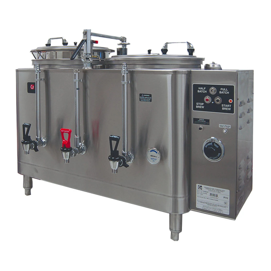
S6161-JB-FSE-010 GENERAL DESCRIPTION This urn is an automatic, pushbutton operated, volume brewing unit. It consists of a non-pressure, vented water tank of large capacity into which two stainless steel liners are inserted. Electric heat is used to keep water in the tank always at the desired temperature. For this type of heat, a ther- mostat, sensing the water temperature and controlling a contactor, switches on and off the electric immersion heater found inside. -
Page 14: Operation Start-Up
S6161-JB-FSE-010 2. An experienced electrician should be responsible for connecting urn to electric power. 3. Check rating marking on urn to be sure supply lines match voltage and phase requirements. 4. Neutral wire normally required on all single phase and on 208 Volt three phase power supplies to operate 120 Volt AC control Circuit. - Page 15 S6161-JB-FSE-010 through heat exchange coil and come out of the spray nozzle and spray over the coffee in the brew basket. The rate at which the water flows is controlled by a two stage water flow regulator system designed to provide accu- rate flow rate under all conditions.
-
Page 16: How To Brew In An Automatic Urn
S6161-JB-FSE-010 HOW TO BREW IN AN AUTOMATIC URN 1. Place filter in brew basket with designated amount of ground coffee (automatic urns are designed to use 1, 2, or 3 lbs. of coffee). Make certain you have a level bed of coffee. 2. -
Page 17: Care And Cleaning Of Coffee Urns
S6161-JB-FSE-010 9. Push brew timer start button and allow to spray-over full timer amount into liner. Check total spray-over water by drawing off into one gallon measure, a gallon at a time. If spray-over is slightly over or under desired amount, change timer setting; longer time to increase amount, shorter time to decrease amount 10. - Page 18 S6161-JB-FSE-010 SEMI-WEEKLY CLEANING PROCEDURE 1. Be sure outer jacket is full of water. 2. Turn on heat and fill urn liner 3/4 full of water; use only urn cleaning compounds (See Note) following manu- facturer’s directions; mix thoroughly and let stand about 30 minutes. 3.
- Page 19 S6161-JB-FSE-010 Figure (3) ROUGH-IN SPECS. FOR AUTO URNS 1-11 / (1-12 Blank)
- Page 20 1-12 @@FIpgtype@@BLANK@@!FIpgtype@@...
- Page 21 S6161-JB-FSE-010 Figure (4) 7400E URN CONTROL CIRCUIT WIRING HARNESS DIAGRAM: NCC TIMER, AUTO REFILL, LOW WATER CUTOFF, OPT. 43 (AIR AGITATION) 1-13 / (1-14 Blank)
- Page 22 1-14 @@FIpgtype@@BLANK@@!FIpgtype@@...
- Page 23 S6161-JB-FSE-010 Figure (5) TAB TERMINAL HEATER WIRING - URNS WITHOUT PUMP 1-15 / (1-16 Blank)
- Page 24 1-16 @@FIpgtype@@BLANK@@!FIpgtype@@...
-
Page 25: Iv. Trouble Shooting Auto Refill, Low Water Cutoff, And Liquid Level Control System
IV. Trouble Shooting Auto Refill, Low Water Cutoff, and Liquid Level Control System. PROBLEM POSSIBLE CAUSE SERVICE CHECK REMEDY A. Overfilling of water compart- 1. Fill solenoid valve leaking due Disassemble and clean out. May require new ment when power to urn is to dirt or scale holding valve plunger assembly. - Page 26 IV. Trouble Shooting Auto Refill, Low Water Cutoff, and Liquid Level Control System. - Continued PROBLEM POSSIBLE CAUSE SERVICE CHECK REMEDY 5. Water strainer clogged. No sprayover on automatic urns. Remove and clean micromesh screen filter located in water strainer. (In line with fill solenoid valve).
- Page 27 IV. Trouble Shooting Auto Refill, Low Water Cutoff, and Liquid Level Control System. - Continued PROBLEM POSSIBLE CAUSE SERVICE CHECK REMEDY F. High speed (rapid fire) chatter- 1. Capacitor failure on liquid Visual and audio. Replace liquid level control. Also, check ing that ends with liquid level level control printed circuit board contactor or steam valve or gas valve, fill...
- Page 28 IV. Trouble Shooting Auto Refill, Low Water Cutoff, and Liquid Level Control System. - Continued PROBLEM POSSIBLE CAUSE SERVICE CHECK REMEDY M. Water never reaches brewing Thermostat set too low. Thermometer needle should stop at Turn thermostat knob to brew. Remove and temperature.
- Page 29 S6161-JB-FSE-010 NOTE Beginning January, 1979, relay no longer plug-in type, but soldered directly to liquid level control. AUTO REFILL AND LOW WATER CUTOFF: WHAT THEY ARE 1. Auto Refill of the water compartment keeps the urn body filled with water. When water is used, the fill valve opens automatically to let in more.
-
Page 30: Quick Service Check Of Liquid Level Control System
S6161-JB-FSE-010 B. Operation Figure (9) Figure (10) QUICK SERVICE CHECK OF LIQUID LEVEL CONTROL SYSTEM 1. All wires secure and property connected. 1-22... -
Page 31: Repair/Replacement Instructions For Electrical And Mechanical Components
S6161-JB-FSE-010 2. Plug-in relay on printed circuit board seated all the way onto socket. 3. Clean the electrodes. Lime (mineral scale) build-up can interfere with the operation of any liquid level con- trol system. REPAIR/REPLACEMENT INSTRUCTIONS FOR ELECTRICAL AND MECHANICAL COMPO- NENTS Thermostat - Part Number 504001 1. - Page 32 S6161-JB-FSE-010 3. Lift complete spray arm assembly off inlet piston. 4. Replace ″O″ rings and teflon seal (see elastomer kit Part Number 521021 - Figure 12) on inlet piston and lubricate with silicone grease. 5. To replace inlet piston, loosen locknut below cam washers and unscrew from hex base fitting. 6.
- Page 33 S6161-JB-FSE-010 a. Place alignment mark on liner ring and urn top. b. Remove screws at top, fastening liner ring to urn body (if supplied). c. Insert 1/4″ x 1-1/2″ x approximately 15″ long flat bar stock into slot in liner drain nut at bottom. d.
- Page 34 S6161-JB-FSE-010 1. Shut off power to urn. 2. Shut off water supply to urn. 3. Remove access cover from control housing. 4. Disconnect 2 brew/refill water solenoid valves from electric circuit. 5. Disconnect tube flare nut on water supply at Y strainer. If slip joint assembly, remove as follows: 6.
- Page 35 S6161-JB-FSE-010 11. Turn on power. Timer - Part Number 507028 - Figure 11 1. Shut off power to urn, and remove access cover from control housing. 2. Disconnect all wiring from timer. 3. Remove 2-6/32 screws from timer dial on front panel of control housing. 4.
- Page 36 S6161-JB-FSE-010 Figure (6) ILLUSTRATED PARTS BREAKDOWN 7400 SERIES 1-28...
-
Page 37: Part Numbers & Quantity Required For 1 Year
S6161-JB-FSE-010 PART NUMBERS & QUANTITY REQUIRED FOR 1 YEAR 1-29... -
Page 38: Part Numbers And Quantities
Part Numbers and Quantities FIG. & 7413 7443 7444 7416 7446 MANUFAC- MFR. MFR. PART REF. DESCRIPTION 7413EX 7443EX 7444EX 7416EX 7446EX TURER CODE GAGE SHIELDS 522003-Coffee Tomlinson Ind. 87294 A-78-10-1/2 522002-Water 87294 A-78-9-1/2 522004-Coffee 87294 A-78-13 522047-Water 87294 A-78-12... - Page 39 Part Numbers and Quantities - Continued FIG. & 7413 7443 7444 7416 7446 MANUFAC- MFR. MFR. PART REF. DESCRIPTION 7413EX 7443EX 7444EX 7416EX 7446EX TURER CODE 513006-Urn Handle 02594 507028-Timer-NCC National Controls 28081 TAM-1432-120 505002-Liquid level 02594 Control 518005-Electrode 02594 Assbly.
- Page 40 Part Numbers and Quantities - Continued FIG. & 7413 7443 7444 7416 7446 MANUFAC- MFR. MFR. PART REF. DESCRIPTION 7413EX 7443EX 7444EX 7416EX 7446EX TURER CODE A-668-2-(208V- 02594 5.5KW-1PH) A-668-5-(208V- 02594 6.0KW-1PH) A-668-1-(240V- 02594 11.5KW-1PH) A-668-2-(240V- 02594 7.0KW-1PH) A-668-5-(240V- 02594 8.0KW-1PH)
- Page 41 S6161-JB-FSE-010 Figure (11) 507028 NCC Timer Figure (12) 505002 Liquid Level Control 1-33...
- Page 42 S6161-JB-FSE-010 Figure (13) 521021- Urn Elastomer Kit Figure (14) Seal Kit P/N 521028 1-34...
- Page 43 S6161-JB-FSE-010 Figure (15) Option 43 Outside Tube Kit P/N 512015 When Supplied. Figure (16) Figure (17) 1-35...
- Page 44 S6161-JB-FSE-010 Figure (18) Figure (19) .5CC Disposable Tube of Loctite 271 Cover Handle Kit for Automatic Urns P/N 513001 1-36...
- Page 45 S6161-JB-FSE-010 SECTION INSTALLATION AND SERVICE DESCRIPTION S301 Standard Open Frame Solenoid Valve is a 2-way, normally closed, direct acting, general purpose type. All stainless steel construction with optional synthetic seating and sealing materials. Valves my be mounted in any position. A spring loaded plunger assures positive shutoff. CS4 solenoid coil is rated at 10 watts.
- Page 46 S6161-JB-FSE-010 3. Apply thread seal sparingly to male threads only. 4. Provide clearance for solenoid removal 5. Wire in accordance with applicable national and local codes. S301 Standard Open Frame Solenoid Valve SERVICE AND REPAIR WARNING Disassembly, reassembly or internal adjustment without factory test may result in hazardous condition.
-
Page 47: Valve Disassembly
S6161-JB-FSE-010 S301 standard solenoid valves provide dependable operation for many years. However, foreign matter between valve seat and disc can cause leakage. VALVE DISASSEMBLY 1. Unscrew hex nut from plunger tube to remove lock-washer, nameplate and spring washer. 2. Lift coil frame, coil and bottom spring washer from valve body. Be careful, do not disarrange solenoid assem- bly. -
Page 48: Recommended Coffee Urn Cleaners
S6161-JB-FSE-010 Manufacturers/Suppliers for Component Parts - Continued Mfg. Code 95263 Leecraft 21-37-44th Rd. Long Island City, NY 11101 28081 National Controls Corp. 9311 N. DuPage Ave. Lombard, IL 60148 77857 Robertshaw Controls New Stanton Division Youngwood, PA Recommended Coffee Urn Cleaners ″DIP-IT″...
Need help?
Do you have a question about the 7443 and is the answer not in the manual?
Questions and answers