
Summary of Contents for Link4 iPonic 600
- Page 1 ™ iPonic I N T E L L I G E N T E N V I R O N M E N T A L C O N T R O L L E R Installation and User’s Guide November 2011 Preliminary Edition Copyright ©...
- Page 2 iPonic ™ I N T E L L I G E N T E N V I R O N M E N T A L C O N T R O L L E R Installation and User’s Guide November 2011 Preliminary Edition Copyright ©...
-
Page 3: Table Of Contents
Optional Ethernet Cable Installation ................11 Equipment Installation ....................12 Low Voltage Output Installation ................. 13 Programming ................. 15 Before You Begin....................... 15 iPonic 600™ Main Status Screens ................15 Navigation ........................15 Main Status Screen Entries ................18 Programming Screens ....................20 1.0 CURRENT SETPOINT PROGRAMMING ............ - Page 4 3.2.4 CO2 ..................... 33 4.0 SYSTEM SETUP ....................34 4.1 Equipment Setup ..................35 4.1.1 Quick Setup ..................35 4.1.2 Advanced ..................... 35 4.1.2.1 Timed Override ................. 36 4.1.2.2 Initial Settings ................37 4.2. Scheduling Setup (Growth Curve Setup) ............. 42 4.3.
-
Page 6: Introduction
The reason why we stand out from others is because of our Link4 Promise: Our passion is to provide growers with intelligent control solutions. We understand controlling your growing environment is critical to your success. -
Page 7: Terms And Conditions
No affirmation of fact or promise made by Link4, whether or not in this contract, will constitute a warranty that the goods will conform to the affirmation or promise. -
Page 8: Installation
4 – Self Drilling Screws. Upon arrival, check the contents with the packing list for damaged or missing components (If you have the Integrated iPonic 600 Series Model, simply mount the panel using the two holes on each side of the unit.. -
Page 9: Mounting The Iponic 600
The use of a sealed outlet is recommended if the power output is exposed to moisture. 4. Identify what type of surface you will be mounting the iPonic 600 and use appropriate hardware to ensure proper mounting and load bearing. Consider the additional weight of the external equipment‟s power cords. -
Page 10: Before You Begin
(HAF) fans) may be active to maintain air movement within the hydroponic environment. Whenever the temperature within the hydroponic facility moves above the cool setpoint, or below the heat setpoint (falls outside the Normal temperature range) the iPonic 600 will enter cooling or heating stages to bring it back in line. -
Page 11: Ramping
Ramping In addition, you have the option of a temperature ramp between the setpoints. Each setpoint time period begins with a Ramp time. The benefit of ramping allows for you to make smooth transitions within the hydroponic facility so that the plants don‟t experience temperature shock. Ramping also saves energy, which translates directly into lower operating costs. -
Page 12: Control Strategy
In order to aid you with the process, Link4 has provided several worksheets in the following pages. It is assumed that you already possess a general understanding of hydroponic growth room controls. If not, please review this section carefully. - Page 13 Figure 3.3 Blank worksheet for setpoints and stages iGrowSeries 100 Installation Manual 960-0001-20...
-
Page 14: Internal Layout
Although the unit is pre-wired it is good to have some familiarity with the internal layout. Manual Override Master Reset Switches Button Screen contrast adjustment Communication Module (OPTIONAL) USB Storage Input Figure 4.2 Board Layout of the iPonic 600 960-0001-20 iGrowSeries 100 Installation and User Manual... - Page 15 Figure 4.3 Electrical Connection Diagram of the iPonic 614 iGrowSeries 100 Installation Manual 960-0001-20...
-
Page 16: Connecting To The Iponic 600
2. You may extend the sensor cable as needed, but be sure to use an adapter and wire approved by Link4 to make any extensions (the wire and adapter can be purchased from Link4). It should be noted that the controller is calibrated for a 50 ft. temperature probe. If additional wires are added or removed, software calibration will be necessary to ensure proper temperature measurement accuracy. -
Page 17: Equipment Installation
Equipment Installation The iPonic 600 has eight (8) 115 VAC electrical outlets, a resettable 15 ampere fuse and a six foot power cord. On each side of the unit the bottom two outlets are ganged, as shown in the Fig.5.2 below, whereas, the top two are independent. -
Page 18: Low Voltage Output Installation
Low Voltage Output Installation Your iPonic 600™ has two (outputs #7 and #8) relays that are provided as dry contacts, i.e. switch closures. If an output is activated to ON, the switch is “closed” (shorted); and if it is activated to OFF, the switch is “open”... - Page 19 iGrowSeries 100 Installation Manual 960-0001-20...
-
Page 20: Programming
Programming Before You Begin Before the iPonic 600™ is programmed, it is recommended that the following steps are followed: Hardware is properly installed and tested with manual switches. All internal switches have been restored back to the OFF state. - Page 21 Navigation further information in this manual. The iPonic 600™ has a unique touch sensitive navigation design that utilizes a touch wheel and 4 navigational touch sensitive “buttons” ( HOME, CANCEL, OK, BACK). The behaviors of the wheel and buttons are ...
- Page 22 960-0001-20 iGrowSeries 100 Installation and User Manual...
-
Page 23: Main Status Screen Entries
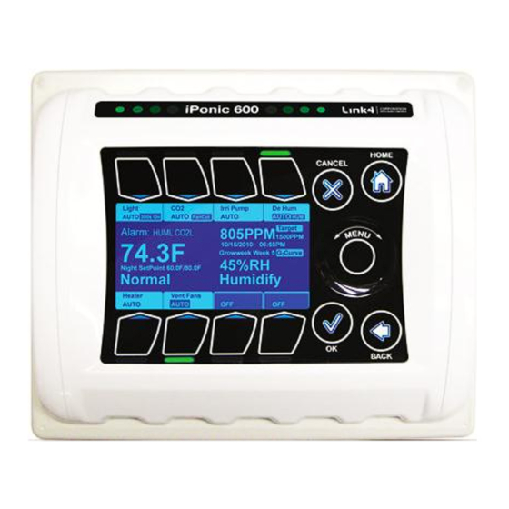
Main Status Screen Entries iGrowSeries 100 Installation Manual 960-0001-20... - Page 24 Note that the display area itself is not touch sensitive. The main status screen displays the current status of your hydroponic growth room compartment. The numbers shown are only sample numbers and will differ for each user, but a description for each display will be explained. ...
-
Page 25: Programming Screens
Programming Screens Once the WHEEL or the OK button is activated, the following six choices will be displayed. This is the main menu for the program. These are the six main programming and report areas:. 1. Current Setpoints - this is where the user can program the temperature and humidity setpoints and the CO2 and light targets. -
Page 26: Current Setpoint Programming
1.0 CURRENT SETPOINT PROGRAMMING From the main menu when you select 1. Current Setpoints, you will see the following screen. Setpoint programming enables the user to program three different setpoints for temperature and humidity during the 24 hour day. The Setpoints Menu can be entered by highlighting the Current Setpoints option on Main Menu using the Wheel or Button #1 and pressing OK. -
Page 27: Temperature Setpoint
1.1 Temperature Setpoint There are three set points provided for the user. NIGHT DAY and NIGHT are active by default. DIF can be turned on if desired. To select Day, Wheel or Button #1 can be used to highlight Day option Day and Night options are the same. -
Page 28: Global Temperature Settings
1.1.1 Global Temperature Settings Deadband functions as a hysteresis when temperature drops to a lower stage of cooling or heating. This prevents the adjacent stages from oscillating back and forth from small temperature fluctuations. Press #1 followed by wheel to increase or decrease deadband value. -
Page 29: Global Humidity Settings
This is the screen you will get when the setpoint is turned OFF. Pressing Tab #1 will turn it back ON. 1.2.1 Global Humidity Settings We can reduce the humidity of the hydroponic facility by turning on the vent fan. But if the outdoor temperature is low or the outside humidity is high we disable the fan. -
Page 30: Co2 Setpoint
1.3 CO2 SetPoint The CO2 setpoint is the threshold below which the CO2 injection will be enabled. Use the wheel to increase or decrease the setpoint value. Press #7 to set the Day and Night start times. Press #8 to go to the Global CO2 settings screen. If the Night CO2 setpoint is ON, then you will see this screen. - Page 31 deadband. If the light level falls below the threshold, the controller will consider this condition to be the "night" condition and stop injecting/ generating CO2. Once the light level has increased beyond the threshold + deadband, the CO2 injection process (if needed) will resume. Press #2 to go to these settings, Use Wheel to select which setting you want.
-
Page 32: Light Settings
1.4 Light Settings Press #1 Change Light Mode. Options are: bank only Alternate banks bank only Both banks Press #2 Change Light Time The option lets you either to set a fixed time window, i.e,, a Turn ON .and a Turn OFF time, or to synchronize the lights ON with the Day Setpoint. -
Page 33: Growth Schedule
2.0 GROWTH SCHEDULE The growth schedule enables the user to set specific temperature, humidity, CO2 and light levels setpoints on a weekly or growing stage basis. The purpose is to eliminate the need to regularly alter the setpoints as the plants are growing but to let the controller do it automatically for you. The Vegetative phase and the Flowering phase let you program one set of setpoints for the entire phase. - Page 34 Here you select which group of four weeks you want to program. Press OK to select. You will then go to the next screen. Here you can select which week you want to program. Press OK to select. You will then go to the screens shown in sections 1.1 -1.4 above.
- Page 35 Press #1 to save your current growth schedule Press #2 to restore a previously stored schedule Press #3 delete a previously stored schedule Please refer to Page No: 51 iGrowSeries 100 Installation Manual 960-0001-20...
-
Page 36: Reports
3.0 REPORTS The third main section of the iPonic 600 controller is the Reports section. This section provides a brief overview of the options available. This section gives the reports and graphs and equipment usage as well as operational costs. User can go to reports... -
Page 37: Temperature
This section allows the user to view the historical data collected by the controller in a graphical manner. Pressing Button #2 from Reports submenu will take the user to graphing submenu. The graphs for the following sensors can be seen: ... -
Page 38: Humidity
3.2.2 Humidity In the humidity option user can view graphs for the following • Inside Humidity • Humidity Setpoint • Dehumidify Setpoint To highlight the sub options Wheel or Buttons #1 - #3 can be used to go to the corresponding options. Pressing OK will let user select the options. -
Page 39: System Setup
4.0 SYSTEM SETUP The fourth option in the menu selection – System Setup – is where the user can set up the equipment at installation time, as well as other miscellaneous operations. Pressing OK or Button #3 will let the user to go to system setup submenu The subsections under the system setup are :... -
Page 40: Equipment Setup
4.1 Equipment Setup In Equipment setup you have two options to choose from- Quick Setup and Advanced. For most grow room applications, Quick Setup will be sufficient. The Advanced option lets the user customize the equipment types, the outputs to which they are connected and the names displayed. 4.1.1 Quick Setup In this screen you can select the equipment that will control your Growth Room and the setup is automatically run by your... -
Page 41: Timed Override
Selecting a channel gets you to the equipment screen. Here you can: Press #1 for Timed Override Press #3 for Initial Settings (set the equipment name, its type, the energy type, etc.) Press #4 for Assign Stages to each of the equipment channels –... -
Page 42: Initial Settings
4.1.2.2 Initial Settings 4.1.2.2.1 Set Type Before equipment can be utilized the proper equipment type must be defined. Press #1 to go to further screens. You can assign a name to the equipment by pressing on #3. This name will be displayed at the MAIN status screen. Please refer to Page No: 41 to change time There are 9 equipment types you can choose from for your particular output.:... - Page 43 In order to change the type to some other type like, from On/Off to Vent as shown in the figure, we get a warning popup as shown in figure. Vents require 2 consecutive output channels (1&2, 3&4, 5&6, 7&8). The first channel (odd numbered) must be wired to Open vent, and the other (even numbered) to CLOSE it.
- Page 44 Rain Vent Open Limit: This is the maximum position the vent can be open when the rain is detected. The value can be changed by selecting Button #1 and the Wheel can be used to modify the value. Wind Vent Override Set Vent Open Limit: This is the maximum position the vent can be open when the wind is at or exceeding a user-specified speed.
- Page 45 can again be opened. By pressing Button #8 user can to go to this option. Wheel can be used to increase or decrease the values Shock Protection: Selecting a shock protection mode helps in opening the curtain slowly, preventing it to open all at once and thus preventing sudden temperature changes.
- Page 46 Irrigation option If you selected Irrigation option in the equipment type, you can see this screen. This option allows you to change the start, end and the amount of time you want to water plants. Press #2 to go to this option. You can enable/ disable this option by pressing #1 Press #5 to change the start time.
-
Page 47: Scheduling Setup (Growth Curve Setup)
4.2. Scheduling Setup (Growth Curve Setup) Press #1 to enable or disable the growth curve process Press #2 to enter the total number of weeks for the growing process. Press #3 to enter the number of weeks for the Vegetative phase. -
Page 48: Sensor Setup
4.3. Sensor Setup The Sensor Setup menu can be found under the System Setup menu. Scroll to the appropriate line using the Wheel or quickly navigate by pressing Button #3 and then OK. In Sensor Setting you have two options Basic: In this option you can select sensor module or an outdoor sensor. -
Page 49: Map Sensors
4.3.1.1 Map Sensors The mapping of the inputs to the different sensors is done here. The figure below shows the different inputs available for mapping. InTemp: Inside Temperature sensor In Hum: Inside Humidity sensor Light: Light sensor OutTemp: Outside temperature sensor Wind: Wind direction and speed sensor Rain: Rain sensor Back up Temp: Back up temperature sensor... -
Page 50: Analog Sensor Mapping
Self Test Time: The time interval between planned sensor tests. Set Retest Time: The delay after which a test should repeat once a previous test has failed. Button #4 is used to go to this option. Set Temp Difference: Temperature difference which should be seen when the test is in progress. -
Page 51: Alarms Setup
4.4 Alarms Setup Selecting this option takes you to the Alarm Settings screen. When an alarm condition occurs, an indication of the alarm will be displayed on the main screen of the controller. If you want the alarm to trigger an external device, such as a “Sensaphone”, you will need to have programmed a channel which you designated as an “Alarm”... -
Page 52: Time/Date Setup
4.5 Time/Date Setup This section allows the user to change the time and date values on the iPonic controller. Time and Date setup menu can be found under system setup menu Wheel or Button #5 can be used to go to highlight this option and OK to select this option. -
Page 53: Advanced
4.6 Advanced Press #1 to go to Global Humidity setting Press #2 to go to Global Temp setting Press #3 to go to Global CO2 setting Press #4 to go to Global Light setting Press #5 to go to Air Exchange Press #6 to change Password Press #7 to run diagnostics Button #8 takes you to more options in Advanced setup... -
Page 54: Diagnostics
4.6.2 Diagnostics Save FS: This option lets you save all the files into a USB. The files include log and configuration files. UI Test This tests the functionality of the touch sensitive user interface. Press #2 followed by conformation to run the test. Pressing a given button highlights it on the screen. -
Page 55: Save/Restore
4.7 Save/Restore This option lets you label and store your program in either the internal memory of the iPonic controller or a USB drive or SD Card. You may have programs for different crops or for different seasons of the year. This will be a convenient way of storing your programs with the capability to restore the program whenever desired. -
Page 56: Save Log Files
4.7.2 Save Log Files To save the log file select the Save Log Files option by highlighting it using the Wheel or by pressing Button #2 and press OK. Currently supported Save Log File options include: • Save History Log File •... -
Page 57: Location Setup
4.8 Location Setup Location setup allows the user to setup the latitude and longitude values. The iPonic controllers have an internal astronomical clock and can calculate the precise sunrise and sunset times once the location of the unit is entered. Location setup menu can be found under system setup menu. -
Page 58: Communication Setup
4.9 Communication Setup The Communication Setup screen can be accessed by navigating appropriate line in the System Setup Menu. Communication setup menu can be found under system setup menu Wheel or Button #7 can be used to go to highlight this option and OK to select this option IP Address Setup: Allows the user to configure the network settings to enable the unit for web access... -
Page 59: Measurement Units
4.10 Measurement Units The units for temperature, wind speed, as well as light can be adjusted under the Measurement Units section of the System Setup. Scroll the Wheel to the desired menu and select OK. The units can be changed by pressing the buttons for the corresponding measurement (Button #5, #6, #7). -
Page 60: Save/Restore Config
5.0 SAVE/RESTORE CONFIG This option lets you label and store your program in either the internal memory of the iPonic controller or a USB drive or SD Card. You may have programs for different crops or for different seasons of the year. This will be a convenient way of storing your programs with the capability to restore the program whenever desired. -
Page 61: Stages
6.0 STAGES The last main section of the iPonic controller is the Stages section. This is where you assign equipment to particular cooling, heating, humidification and dehumidification stages. The Stage settings can be set for: • Temp Stages • Humidity stages Note: There are up to 8 temperature stages and 4 humidity/dehumidify stages. -
Page 62: Temperature Stages
6.1 Temperature Stages Here you can quickly set the temperature stage options for every piece of equipment. The arrows are used for moving the highlight cell to the desired stage. The Setup and OK buttons are used to select or deselect the highlighted stage for a device. For On/Off device types all stages are active i.e. - Page 63 NOTES AREA iGrowSeries 100 Installation Manual 960-0001-20...
- Page 64 NOTES AREA 960-0001-20 iGrowSeries 100 Installation and User Manual...
- Page 65 VISIT US ON THE WEB! • Product Information • User Manuals • Quick Start Guides • Firmware Upgrades www.iponic.link4corp.com iGrowSeries 100 Installation Manual 960-0001-20...
- Page 66 No affirmation of fact or promise made by Link4, whether or not in this contract, will constitute a warranty that the goods will conform to the affirmation or promise.
- Page 67 Ramping In addition, you have the option of a temperature ramp between the setpoints. Each setpoint time period begins with a Ramp time. The benefit of ramping allows for you to make smooth transitions within the hydroponic facility so that the plants don‟t experience temperature shock. Ramping also saves energy, which translates directly into lower operating costs.
- Page 68 Although the unit is pre-wired it is good to have some familiarity with the internal layout. Manual Override Master Reset Switches Button Screen contrast adjustment Communication Module (OPTIONAL) USB Storage Input Figure 4.2 Board Layout of the iPonic 600 960-0001-20 iGrowSeries 100 Installation and User Manual...
- Page 69 Equipment Installation The iPonic 600 has eight (8) 115 VAC electrical outlets, a resettable 15 ampere fuse and a six foot power cord. On each side of the unit the bottom two outlets are ganged, as shown in the Fig.5.2 below, whereas, the top two are independent.
- Page 70 Low Voltage Output Installation Your iPonic 600™ has two (outputs #7 and #8) relays that are provided as dry contacts, i.e. switch closures. If an output is activated to ON, the switch is “closed” (shorted); and if it is activated to OFF, the switch is “open”...
- Page 71 960-0001-20 iGrowSeries 100 Installation and User Manual...
- Page 72 Main Status Screen Entries iGrowSeries 100 Installation Manual 960-0001-20...
Need help?
Do you have a question about the iPonic 600 and is the answer not in the manual?
Questions and answers