
Related Manuals for Roma Medical Reno II P319


Summary of Contents for Roma Medical Reno II P319
- Page 1 Reno II Model – P319 USER MANUAL Please ensure that this manual is read and understood before using the powerchair. Oct 2014 KB&S17249 Rev 1...
-
Page 2: Table Of Contents
Contents Page Introduction Intended Use Technical Specification Feature Guide Safety Advice Adjustments & Battery Removal Joystick depth Footplate height Seat swivel Arm width Flip up armrest & angle adjustment Battery removal VR2 Joystick Controller Brake Release / Freewheel Operation Starting to Drive ... -
Page 3: Introduction
Introduction Congratulations on your purchase of the ROMA Reno powerchair. This powerchair incorporates the latest innovative designs. The ROMA Reno can be used in confined spaces both indoors and out. The powerchair can be easily dismantled without tools and will fit into the boot of vehicles for easy transport or stored neatly indoors. The detachable battery pack allows convenient charging wherever necessary. -
Page 4: Feature Guide
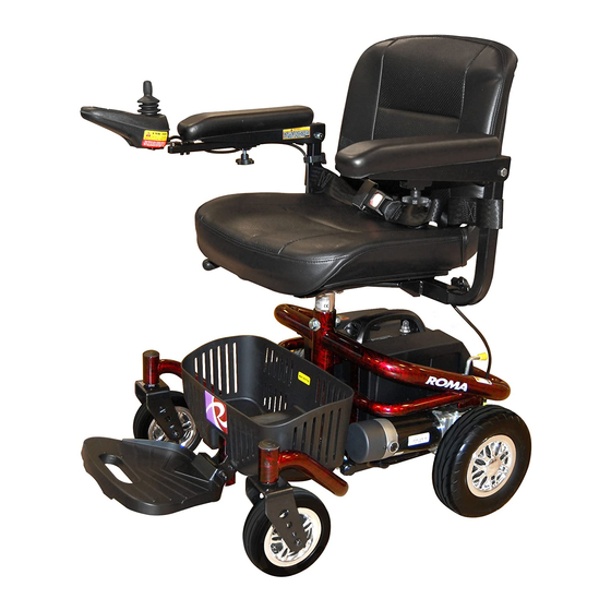
Feature Guide ‘Reno’ 1. Programmable joystick controller 2. Flip up, width adjustable armrests 3. Padded seat and fold down backrest 4. Removable battery pack 5. Rear anti-tippers 6. Puncture proof non-marking wheels 7. Flip up and depth adjustable footplate 8. Handy storage basket... -
Page 5: Safety Advice
Safety Advice Read this manual carefully before using your powerchair Turn the power off when transferring to and from the powerchair Select a slow speed when going down gradients (max 6°) or over uneven ground Keep your feet on the powerchair whilst driving ... -
Page 6: Adjustments & Battery Removal
Adjustments and Battery Removal Joystick Depth Adjustment It is possible to adjust the depth of the joystick controller for added comfort. Simply loosen the handknob and slide the joystick to the required distance and fully re-tighten the handknob. Footplate Height Adjustment The height of the footplate can be adjusted by fully undoing the two fixing bolts. -
Page 7: Seat Swivel
Continued….. Seat swivel & Removal The seat can be swivelled around the base unit. Lift up on the lever on the right side of the seat and rotate as necessary. To remove the seat fold down the backrest, lift up the lever and gently pull the seat upwards away from the chair at the same time. -
Page 8: Flip Up Armrest & Angle Adjustment
Continued….. Flip up armrests & angle adjustment The armrests flip up to allow for easier transfers. Simply lift the armrest when transferring. The angle of the armrest can be adjusted by undoing the locking nut and setting at the desired height. The nut should then be tightened to lock the adjustment in place. Battery removal The battery can be easily removed for charging away from the powerchair or for storage. -
Page 9: Vr2 Joystick Controller
Continued….. VR2 Joystick Controller Battery Gauge (1) This is a 10-segment display, which indicates if the VR2 is switched on and gives the state of charge of the battery. Also, any faults in your power chair’s electrical system are also indicated by this display. -
Page 10: Brake Release / Freewheel Operation
Continued….. Joystick ‘Lock’ Function Your VR2 controller is equipped with a lock function to prevent any unauthorised use. To lock the controller: When the power is on, press and hold the power button for about 1 second until the system bleeps. ... -
Page 11: Starting To Drive
Starting to drive your powerchair Getting Started Select an area with plenty of space. Ensure that when seated in the in the powerchair you are in a comfortable position and can easily and freely operate the controls. Moving off and steering Turn the power on and check that your battery is fully charged. -
Page 12: Reaching And Stretching
Continued….. Drop Kerb Descent Do not reverse down drop kerbs, please use a ramp/drop-kerb in forward motion to descend. Warning: NEVER reverse down a drop kerb or ramp onto a main thoroughfare. Reaching and Stretching Care must be taken when reaching and stretching for objects as this may affect the stability of the powerchair. -
Page 13: Disassembly & Assembly
Disassembly & Assembly Warning: We advise caution when disassembling and lifting items. You must ensure that the person undertaking the action is able to safely and correctly handle the weight to avoid any personal injury. Ensure that the power is switched off and the joystick cable is disconnected before dismantling. - Page 14 Continued….. To reassemble locate the pivot pin of the front chassis into the receiving slots of the rear chassis (each side) and lowered to the bottom location. Fully located in the bottom position...
- Page 15 Continued….. Push down on the rear part of the frame as shown below. This will reconnect the two parts of the frame together. You will hear the latch ‘click’ into place. ALWAYS check that both parts are fully connected before refitting the seat and battery box.
-
Page 16: Battery And Battery Charger
Battery and Battery Charger IMPORTANT: The VR2 controller MUST be switched off when charging. Battery Charger The battery charger is a 4 amp switch mode type off board. The battery charging port is located on the underside of the joystick controller. There is also a charging port on the battery pack. -
Page 17: Maintenance
Maintenance Product Life Expectancy Your powerchair has been designed to provide the user with a long, reliable life provided it is correctly maintained and regularly serviced by an authorised dealer. However, due to inevitable wear and tear and technological improvements it is recommended that the average useable life of this powerchair is five years. -
Page 18: Check List
Continued….. Check List If your powerchair fails to operate, please check the following: The unit is switched on. All plugs and connections are firmly fixed. Battery level shows full charge. Freewheeling device is in the drive position. ... -
Page 19: Further Information
Further Information Safety Information Regarding Electromagnetic Interference (EMI) Powerchairs and powerchairs are designed to operate under certain conditions. However, radio waves or electromagnetic fields may affect the operation of the powerchair. The source of EMI could be radio or television transmitters or portable devices such as mobile phones, portable CB radios etc. - Page 20 Continued….. Product Stability Powerchairs are designed to allow the user flexibility of movement in restricted areas. Driving at maximum speed and attempting sharp turns can create a situation where the product becomes unstable. Therefore it is essential that the user pay attention the guidance set out in this manual.
- Page 21 Continued….. Transportation The P319 Reno Powerchair was tested to ISO 7176/19 on .09.10.2014.by Millbrook Services Test No...S13301 The test chair was fitted with a high back seat and Unwin Safety Systems items 1pair x Quattro with tongue and buckle fro the front (FR 01) 1pair x Quattro with Karabiner for the rear ( FR 02) 3point Occupant restraint (OCR01) Other systems are available for these wheelchairs, for further details please contact the...
- Page 22 Notes...
- Page 23 Notes...
- Page 24 Warranty Terms and Conditions This is to certify that your Roma Medical product is warranted for a period of 12 months from the date of original purchase. This warranty is not transferable. Should a defect or operating fault arise within this period the Dealer from where the product was originally purchased should be notified immediately.
Need help?
Do you have a question about the Reno II P319 and is the answer not in the manual?
Questions and answers