Table of Contents
Advertisement
Advertisement
Table of Contents

Related Manuals for Microdigital MDR-AH Series

Summary of Contents for Microdigital MDR-AH Series
-
Page 1: User Manual
INSTRUCTION MANUAL (MDR-AHxxxx Series _Ver. 1.0) H.264 Video Compression Analog HD Digital Video Recorder User Manual About this user guide Before installing and using this unit, please read this user guide carefully. Be sure to keep it handy for later reference... -
Page 2: Safety Precautions
Safety Precautions Explanation of Graphical Symbols This symbol indicates the presence of important operating and maintenance (servicing) instructions in the literature accompanying the product. This symbol indicates the presence of Uninsulated ”dangerous voltage” within the product’s enclosure that may be of sufficient magnitude to constitute a risk of electric shock to persons. - Page 3 These precautions must be followed for safety reasons. Warning Do not uses if the unit emits smoke, strange sounds are heard, or odor is emitted. Make sure the power cable is not damaged. Make sure there is no dust accumulation on the power plug or the outlet. ...
-
Page 4: Product Components
Product Components The package contains the main unit and its components as specified below. When you purchase the unit, Please check to ensure the components specified below are included. DVR Set (4/8/16ch) Client Software CD Remote Control Battery1.5V (AAA x 2EA) Quick Guide HDD data power cable(SATA) HDD mounting bracket &... - Page 5 Mounting the HARD DISK (4/8/16ch) Remove the screws and the top cover How to mount HDD x 1 1. Mount the HDD into bottom 2. Mount the HDD into bottom 3. Connect the HDD SATA and case as specified above case as specified above HDD power cable as specified above...
-
Page 6: Compatible Hdd Models
Basic function of the MOUSE ① Left button: SELECT function ② Wheel: MOVEMENT function on a drop-down menu Compatible HDD Models 제조회사 모델명 용량 SATA Type BUFFER Seagate ST4000VM000-1F3168 [fw: SC25] 4 TB SATA 3 5900 RPM 64 MB ST3000VX000-1CU166 3 TB SATA 3 7200 RPM... - Page 7 ST3500413AS 500 GB SATA 3 7200 RPM 16 MB ST3500830SCE 500 GB SATA 2 7200 RPM 8 MB ST3500418AS 500 GB SATA 2 7200 RPM 16 MB ST3500410AS 500 GB SATA 2 7200 RPM 16 MB ST3500312CS [fw: SC13] 500 GB SATA 2 5900 RPM 8 MB...
- Page 8 WD10PURX-64D85Y0 1 TB SATA 3 64 MB / WD10EURX-64RPPY0 WD10EURX-63FH1Y0 1 TB SATA 3 5400 RPM 64 MB WD10EZRX-00A8LB0 1 TB SATA 3 5400 RPM 64 MB WD10EARS-00Y5B1 1 TB SATA 3 5400 RPM 64 MB WD10EVDS-63U8B1 1 TB SATA 3 7200 RPM 32 MB WD10EALX-229BA1...
-
Page 9: Specifications
Specifications Please note that specifications and unit exterior design are subject to change without notification MODEL 16CH Description 960H / AHD 2.0 (720p & 1080p) Hybrid DVR Number of Channels Input Camera 720p25/30/50/60, 1080p25/30 or NTSC/PAL Video Main Monitor HDMI and VGA(Max. 1920x1080) Output Sub Monitor CVBS or SPOT... - Page 10 e-SATA None Front Rear User I/F Input Method IR, Mouse, Keyboard Controller 10/100/1000 Network Interface 10/100 Base-T Base-TX Network Dynamic DNS Yes (Free DDNS) Dual Encoding for Network Digital Zoom DLS (Day Light Saving) NTP (Network Time Protocol) Features S.M.A.R.T Internal Beep Multi-Language e-mail Notification...
-
Page 11: Table Of Contents
Table of Contents Main Features ......................14 Name, Function and Connection ................15 2-1. Front Panel ........................... 15 2-2. Rear Panel ........................... 15 2-3. Remote control ..........................16 Setting up the DVR ..................... 17 3-1. Setup – Main Screen ........................17 3-1-1. - Page 12 4-4. Digital Zoom in Live and Playback Screen ..................49 5. PTZ Control ........................50 6. Back up ......................... 51 6-1. Still Image backup onto USB flash Drive..................51 6-2. Video backup onto USB flash Drive ....................51 6-3. Transferring still images or video from the ARCHIVE list .............. 52 6-4.
- Page 13 9-7-8. Upgrade ............................ 90 9-7-9. Information ..........................90 9-8. Operation ............................. 91 9-8-1. Addition, Delete, and modify of DVR sites ................. 91 9-8-1-1. Addition of sites ........................91 9-8-1-2. Delete of sites ........................91 9-8-1-3. Modify of sites ........................92 9-8-2.
-
Page 14: Main Features
1. Main Features All Video input is detected automatically(Analog / 960H / AHD 720p / AHD 1080p) H.264 Video compression Reliable File system HDMI & VGA Output 4 channel audio recording Individual channel operation ... -
Page 15: Name, Function And Connection
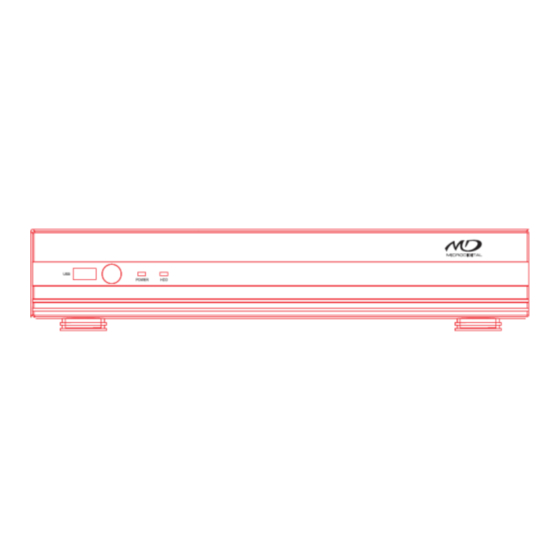
2. Name, Function and Connection 2-1. Front Panel The following information will help you to operate the front panel controls. 4/8/16 CH Name Description POWER LED light is on when power is applied to the system. LED light is on when the system is recording video data. There is a USB port located on the left side of the front panel. -
Page 16: Remote Control
Table 2.2.1. Rear panel connections Connection Purpose VIDEO IN connectors for video input. (960H & Analog HD) AUDIO IN 4 connectors for audio input. AUDIO OUT 1 connector for audio output. HDMI OUT connectors for main video output. HDMI VGA OUT Connector for VGA monitor. -
Page 17: Setting Up The Dvr
During playback – To move the playback position 60 seconds forward . During Pause – To move the playback position moves 1 frame forward ⑤ F/REW: During playback – To move the playback position 60 seconds back. ... -
Page 18: Setup - Menu Tree
To enter the setup menu, select a right button of the mouse or press the SETUP button on the remote control. Table 3.1.1. Setup menu tree When the DVR prompts the LOG-IN window, enter the PASSWORD using the virtual keyboard, or the front panel, or the remote control. - Page 19 NAME COVERT BRIGHTNESS CONTRAST SATURATION – MAIN OUTPUT RESOLUTION – SUB MONITOR OUTPUT(CVBS/SPOT) RECORD – CHANNEL RESOLUTION FRAME RATE QUALITY RECORDING SENSOR RECORDING PRE RECORD POST EVENT RECORD AUDIO SCHEDULE DEVICE – ALARM OUT ALARM DURATION – CONTROLLER & PTZ CONTROLLER - SPEED - ID...
- Page 20 – RECORDING LIMIT RECORDING LIMIT DAYS SYSTEM – DVR-ID – DESCRIPTION – LANGUAGE – DATE FORMAT – SET DATE & TIME TIME DISPLAY FORMAT TIME ZONE DAYLIGHT SAVING SET DATE & TIME – CLIENT ACCESS – – SEND EMAIL –...
-
Page 21: Setup - Display Mode
QUALITY – WIRELESS LAN CONFIG – SAVE SETUP TO A USB – LOAD SETUP FROM A USB – LOAD DEFAULT – LOAD FACTORY DEFAULT – SOFTWARE UPGRADE 3-2. Setup – Display Mode In the SETUP menu, select the DISPLAY tab. Then, the DISPLAY menu is displayed as pictured below. Navigate through the menu items or change the settings using the mouse or the remote control. -
Page 22: Setup - Recording Mode
SEQUENCE Enable/disable sequential display of video in full screen mode. SEQUENCE- Set the dwell time of each, single channel display in sequential display mode (3~60seconds) DWELL TIME Select a channel to apply the name and covert settings change using CHANNEL the mouse or the remote control. - Page 23 Navigate through the menu items or change the settings using the mouse or the remote control. Figure 3.3.1. Recording mode setup screen Table 3.3.1. Menu items in Recording mode setup Menu item Description Select a channel for applying the following settings using the mouse or the CHANNEL remote control.
-
Page 24: Recording Schedules
RECORDING PRE RECORD Enable/disable pre-event recording. Options are: OFF, 15 seconds, 30 seconds, 1 minute, 3 minutes and 20 minutes. POST EVENT Set the post event recording time duration for the specified channel. (10~60 RECORD seconds) AUDIO Enable/disable audio recording for the specified channel. SCHEDULE Set the recording schedule. - Page 25 Figure 3.4.1. Device mode setup screen Table 3.4.1. Menu items in Device Setup screen Item Description ALARM OUT Only one Alarm-out is available. Set alarm dwell time from 5 to 60 seconds or infinite. /ALARM DURATION CONTROLLER & PTZ Set the controller and PTZ camera speed, number, type and ID. CHANNEL Select specified channel for motion zone setup.
-
Page 26: Controller & Ptz Setup
REMOTE CONTROL ID Set the remote control ID. 1. Select ID. 2. Input the remote control ID number. 3. An icon will indicate on the Live Screen if the remote control ID is synchronized. The options are from 0 to 99 Select the type of each sensor. -
Page 27: Motion Zone Setup
Figure 3.4.1.2. Controller Selection Screen 3-4-2. Motion Zone Setup Select MOTION ZONE using the mouse or the remote control and select either PARTIAL ZONE or FULL ZONE using the mouse control. The default value is FULL ZONE. If FULL ZONE is selected, the motion setting screen is not displayed. Only set the level of sensitivity for MOTION SENSITIVITY. -
Page 28: Setup - Storage Mode
3-5. Setup – Storage Mode In the SETUP menu, select the STORAGE tab. Then, the STORAGE menu is displayed as pictured below. Navigate through the menu items or change the settings using the mouse or the remote control. Figure 3.5.1. STORAGE setup screen Table 3.5.1. -
Page 29: Setup - System Mode
RECORDING LIMIT Enable/disable recording limit. RECORDING Set the recording limit days. (1- 90 days) LIMIT DAYS If the RECORDING LIMIT DAYS are set to 1, the data will be overwritten after 24 hours. 3-6. Setup – System Mode In the SETUP menu, select the SYSTEM tab. Then, the SYSTEM menu is displayed as pictured below. Navigate through the menu items using the mouse or the remote control and change the value of the menu... - Page 30 Figure 3.6.1. SYSTEM Setup Screen Table 3.6.1. Menu items in SYSTEM Setup screen Item Description DVR ID Name the DVR (e.g. Factory, Library, Store, Location etc) This is to used to identify the name of each DVR under the same network. Press the button to view the system information.
- Page 31 DAY LIGHT SAVING Select DAYLIGHT SAVING using the mouse or the remote control and select the appropriate daylight saving time zone. If choosing EU or OTHERS, set the applicable conditions. The options are: OFF / USA / EU / OTHERS OFF: Daylight saving is turned off.
- Page 32 CONNECTION PERIOD TIME – Refresh the time at the designated time (e.g. 1AM) INTERVAL – Every 1 hour ~ 24 hours ONCE – Synchronizes time only once. NTP will not synchronize unless the Connection Mode is changed. DVR sends E-MAIL Notification when the NTP server time is faster than the system time with bellow message.
- Page 33 SYSTEM EVENT NOTIFICATION HEALTH CHECK – OFF, ON (Allows the user to set MAIL STATUS periodically) : DAILY or WEELY or MONTHLY VIDEO CLIP SETUP – Set video recording time for the e-mail appending Features motion detection or alarm input events only EVENT AND NOTIFICATION –...
-
Page 34: Setup - Security Mode
HDD FAILURE – Enable Email, Beep and Alarm output Notification when the HDD fails. 3-7. Setup – SECURITY Mode In the SETUP menu, select the SECURITY tab. Then, the SECURITY menu is displayed as pictured below. Navigate through the menu items or change the settings using the mouse or the remote control. Figure 3.7.1. - Page 35 ADMIN, NETOWRK, USER1, USER2, USER3: V check: It means the user can access to the function. Blank: It means the user cannot access to the function. Change the name of USER1, USER2 and USER3. USER NAME Click “ENTER” after naming. USER PASSWORD Options are ADMIN, USER1, USER2 and USER3.
-
Page 36: Setup - Network Mode
Allows specific users to view selected channels or block the view of NETWORK LIVE AUTHORITY selected channels. When user set this function, they can see a user login window. Then, user can select one of user types ◀ ▲ ▶ ▼ (ADMIN, USER1, USER2, USER3) using the mouse or the control button ( ) on the remote control. -
Page 37: Port, Network Audio Port And Web Port
PORT has to be the next number of the DVR port. (PORT + 1). WEB PORT Enter the port number for connection using web. Default is 80. Select a type of network connection. NETWORK TYPE DVR will automatically retrieve an IP address. DHCP Network information must be manually configured STATIC... -
Page 38: Network Types
3-8-2. Network Types 3-8-2-1. DHCP An IP address is automatically assigned by the DHCP server, which automatically assigns IP address and other parameters to new devices. When ADSL or other network being used adopts variable IP method, not fixed IP. This option is used as a way to automatically get IP address. -
Page 39: Network Stream
Figure 3.8.3.2. Network setup screen – DDNS Server 2 3-8-4. Network Stream User can set the resolution, the frame rate and the quality for a network stream classified by channel. It is recommended that user should adjust each item to proper level to get the network service smoothly. The maximum value for the network stream is VGA 15fps per channel but the recording resolution and frame rate are sending when only one user connects to the one channel mode via network. - Page 40 Figure 3.9.1. Config setup screen Table 3.9.1. Config setup Item Description SAVE SETUP TO User can save the current configuration (Setting values) of the DVR to the USB flash drive. Plug in the USB flash on the front panel and press A USB the button to start the saving process.
-
Page 41: Live, Search And Playback
SOFTWARE Upgrade softeware to the latest version. UPGRADE After connecting USB flash drive to USB port on the DVR, click SEARCH. It will automatically find the upgrade file. Please refer to 7. Upgrading Firmware. 4. Live, Search and Playback 4-1. Live Viewing Screen In the Live screen, video inputs from the cameras are displayed as they are configured in the Display Setup screen. - Page 42 Indicates that HDD is recycled. Continuous recording in progress. Manual recording in progress. To set the Manual recording mode, press the Record button on the front panel. Motion alarm recording in progress. Sensor recording in progress. Indicates that the lock is set. To Audio mute.
- Page 43 Table 4.1.2. Menu Items in Quick Operation Window Icon Description Select this option to enter the Setup menu. SETUP Select this option to mute audio on all channels. AUDIO SEARCH Search button. Click this button to enter the search menu. BACKUP Capture pictures and store as BMP files CAMERA PTZ...
-
Page 44: Search Screen
4-2. SEARCH Screen To enter the search screen, select SEARCH menu on the screen using the mouse or press SEARCH icon on live screen. Figure 4.2.1. Search Screen There are 7 ways of search menu such as TIME LINE (Calendar), EVENT, GO TO FIRST TIME, GO TO LAST TIME, GO TO SPECIFIC TIME, ARCHIVE LIST, and LOG LIST on the screen. -
Page 45: Event Search
Figure 4.2.2. Time Line Search screen When it clicks a Timeline menu, user can see a calendar which has recording data. Select a specific date and time. Use a drag-and-drop function of the mouse control. User can select a specific minutes using a button in the above red box. -
Page 46: Go To First Time
Figure 4.2.3.1. Event Search screen When the Event menu is selected, the user can see a calendar, which has recorded data. Select a specific date and the event log will be displayed. Press the PLAY button to playback the data or the SAVE button to save the data after selecting the specific data. -
Page 47: Log Search
Figure 4.2.6 Archive Search Screen When it clicks an Archive menu, user can see a calendar which has recording data. Select a specific date and then user can see all data. When it presses a Display button, the still image or the first frame of the selected video is opened and user can save the data. -
Page 48: Play Mode
4-3. Play mode During playback of a recorded event, the mode changes from SEARCH to PLAY. While in PLAY mode, you may return to the SEARCH screen by pressing the X button on the status bar or the ESC button of a remote control. -
Page 49: Digital Zoom In Live And Playback Screen
4-4. Digital Zoom in Live and Playback Screen DVR series supports Digital Zoom feature during live and playback mode. 1. Double click the target channel. 2. Click the left button of the mouse and drag to make rectangular shape. -
Page 50: Ptz Control
5. PTZ Control To control the PTZ functions of the camera, select PTZ menu on the screen using the mouse. Please refer to the table 5.1. for the control. Table 5.1. Button Functions in PTZ Control Item Description INITIALIZE Initialize the PTZ settings of the selected camera. ◀... -
Page 51: Back Up
6. Back up 6-1. Still Image backup onto USB flash Drive Still images can be captured and archived onto the USB flash drive or an USB external hard drive in live mode or while playing back recorded video. In live mode, press the BACKUP button to launch the archive function or select BACK UP menu on the screen using the mouse. -
Page 52: Transferring Still Images Or Video From The Archive List
Figure 6.2.1. Video Archiving and Backup Screen 6-3. Transferring still images or video from the ARCHIVE list The stored data onto hard drive will be found in the ARCHIVE list in SEARCH window. User can back up still images or video into the storage device from the ARCHIVE list. 1. -
Page 53: Playback Of Backup Video
Figure 6.3.1. Archive Search Screen 6-4. Playback of Backup Video NSF format: NSF format video can be played back by the player (the HD player) that the DVR copies on USB flash drive with video. Two folders are copied on USB flash drive - BACKUP DATA: NSF format video file and INDEX file for a title file of date and time - HD PLAYER: Exclusive video viewer. -
Page 54: Upgrading Firmware
AVI format: It can be played back by Window Media Player™ or other media player that is compatible with AVI format video. Timestamp On AVI. The subtitle is embedded to the video clip file. The subtitle is embedded to the AVI file. 7. - Page 55 2. You can see the following message when pressing the software upgrade menu after putting the USB memory drive on the system. 3. You can see the following message when pressing the scan button. Please check the current firmware version and the firmware version which you want to upgrade. The system will upgrade automatically when pressing the upgrade button.
- Page 56 NOTICE If selecting REBOOT LATER, the upgraded software will not be applied until the system reboots. If selecting REBOOT NOW when the USB flash drive is plugged, the following message will pop up. Remove the USB flash drive and select OK. Remote Firmware Upgrade User can upgrade the firmware via Network as follows.
- Page 57 2. Press the password for admin. Just admin is possible to connect to the remote setup menu. 3. Go to the Remote Upgrade menu. Then, you can see the current F/W version as follows. To upgrade a new F/W, insert the F/W in your PC and press the UPGRADE button. 4.
-
Page 58: Network Access Using The Exclusive Network Viewer, Ums Single
5. When finishing the upgrade, the network streaming would be connected again automatically and you can see the following screen. Please check the current F/W version if the upgrade is succeeded. 8. Network access using the Exclusive network viewer, UMS single The DVR provides a live remote monitoring feature. -
Page 59: Installing The Network Viewer
O/S: Windows 2000, XP Professional, XP home, Vista, 7(NOTE: Not all versions of Vista and 7 are supported) Direct X: DirectX 9.0c or higher 8-2. Installing the network viewer 1. Insert the provided CD in the CD drive and double-click “UMSClient(XXXX).exe” 2. -
Page 60: Live Monitoring Mode And Functions
8-3. Live monitoring mode and functions. Button Function Description Displays the current date and time. DATE & TIME CONNECT/DISCONNECT Connect/disconnect network connection. SEARCH Switches the live mode to search mode. DISPLAY MODE Select a channel and screen display mode. PAN/TILT/ZOOM/ FOCUS Control the PAN / TILT / ZOOM / FOCUS features on the remote camera. - Page 61 ALARM The ON/OFF button of the alarm output of the DVR. When an alarm of the DVR is output, this button becomes Red. DVR HDD storage Indicator. HDD USAGE NETWORK BANDWIDTH Shows the transferred frames and network bandwidth. AUDIO Adjust the volume. The audio can be turned on or off by clicking the audio icon.
-
Page 62: Bi Directional Audio
Image capture of live screen Still-image of live screen can be captured and saved as BMP or JPEG file. 1. Click the channel to be captured. Then the channel screen is surrounded with a red line. 2. Click the CAPTURE button. Then the IMAGE CAPTURE dialog is displayed. 3. - Page 63 DISCONNECT Disconnect network connection.. LIVE Switches the search mode to live mode. DISPLAY MODE Select a channel and screen display mode. SEARCH The calendar shows dates with recorded video in a light blue and the selected date in dark CALENDAR blue.
- Page 64 The timeline shows recorded data in color on the bar. You can adjust the timeline scale and move it to the time you wish to playback. Then click the play icon to display the recorded video. CHANNEL To display the recorded data of selected channel or all channels on a time line scale.
-
Page 65: Pc System Configuration
Backup of video in the remote DVR Video recorded in the remote DVR cab be backed up on the PC HDD as AVI format. 1. Connect the network to the remote DVR and play the video recorded in the remote DVR. 2. - Page 66 Setting General Set the Security Option, Save Path, and Miscellaneous. Security Option: Set a password for security options. When you access any of the selected functions, you will need to enter the password. Save Path: Specify the location to record for backup and still image capture. ...
- Page 67 ID: Input ID of DVR. Default ID is “admin”. Password: Input network password of DVR. Default Password is “1111”. Click OK button. And then the registered site is added on the directory window. Setting Event Set the record path and the size of local disk space for the log files. ...
- Page 68 Setting Record Record Setup: You can set the recording conditions as the following; Always, Event, or Auto record. And you can also select target DVR/DVRs and channel/channels When you set the recording condition to event, you can set event for motion or alarm with duration. Record Local Storage Setup: You can select the local disk to record and the amount of disk space you want to allow the program to use for recording.
- Page 69 Setting Secondary Monitor Used to calibrate the second monitor image. Setting Language English, French and Spanish is selectable. About “About” provides network client version information.
-
Page 70: Ums Client Connection
8-7. UMS Client Connection CONNECT button to appear on the site registered under the ”OK” button Click is pressed, the connection to the site. If you want to connect directly to an IP address or Domain address to “OK” button... -
Page 71: Network Access Using The Exclusive Network Viewer, Ums Multi
9. Network access using the Exclusive network viewer, UMS Multi 9-1. Overview The UMS Multi-Client is a multiple site monitoring client software with; video, audio, and alarm signals from the DVRs over networks. The UMS Multi-Client does not limit the number of DVR units to register. The program displays to up 256 live videos on one display and even playback videos window on the same or another display monitor. -
Page 72: Installing The Program
9-3. Installing the program 1. Insert the provided CD in the CD drive and double-click “UMSMultiClient (XXXX).exe” 2. Select a destination folder and click “Next”. 3. Select the program folder and click “Next”. 4. The setup status screen is displayed. 5. -
Page 73: Live Window
9-4. Live Window When installation is completed, double click the “UMS Multi Client” icon on your desktop to start the program. 9-4-1. Main user interface 9-4-2. Control buttons Button Description Click this icon to run a playback window to search and play videos that are recorded in local PC. - Page 74 Click this icon to disconnect the selected site/sites. DISCONNECT Click this icon to setup configuration of UMS MULTI CLIENT. SETUP Click this icon to capture a still image CAPTURE Opens list of events logged by the UMS Multi Client. EVENT LIST Click this icon to play/pause live video.
-
Page 75: Search And Playback Window
9-5. Search and Playback Window 9-5-1. Main user interface You can access to search window by clicking the search icon (Local Playback / Remote Playback) on the upper left of Live Window. 9-5-2. Main control panel Button Description Click this icon to run a playback window to search and play videos that are recorded in local PC. - Page 76 Click this icon to capture a still image. CAPTURE Opens list of events logged by the UMS Multi Client. EVENT LIST Click this icon to set the beginning time for backup of the recorded MARK IN video in AVI format. Click this icon to set the ending time for backup of the recorded video MARK OUT in AVI format.
-
Page 77: Setup Of Ums Multi Client
Thumbnail search over the network. - List the thumbnail 24images from 00:00 to 23:00. - Select one of 24 images every 150sec for an hour. - Then play the tile * Click the “PREVIOUS” button to go the previous step. 9-6. -
Page 78: Event
9-6-2. Event Event log can be archived and searched. Event Log: Specify the location to save event logs and select event to archive. Event Search: Event log can be searched from the selected time. -
Page 79: Record
9-6-3. Record Record Setup: You can set the recording conditions as the following; Always, Event, or Auto record. And you can also select target DVR/DVRs and channel/channels. When you set the recording condition to event, you can set event for motion or alarm with duration. Record Local Storage Setup: You can select the local disk to record and the amount of disk space you want to allow the program to use for recording. -
Page 80: Display
9-6-4. DISPLAY You can select the OSD (On Screen Display) to be displayed. 9-6-5. Language You can select a language to be display. -
Page 81: About
9-6-6. About “About” provides network client version information. 9-7. Remote Setup The menu settings for the DVR unit can be set over network. Put the cursor of the mouse on the channel, which is connected to the site and right click on the mouse to open the submenu. -
Page 82: Display
NOTICE Web Setup is prohibited when DVR is in local Setup Menu. 9-7-1. Display Select the DISPLAY tab to set the DISPLAY conditions. These settings apply to all channels. OSD: Sets whether to display or not date and time as well as channel number on the screen. ... -
Page 83: Record
SEQUENCE DWELL TIME: Sets the interval for automatically switching the screens. CHANNEL: Name, Covert, Brightness, Contrast, Hue, Saturation, These settings apply to the specified channel only. 9-7-2. Record Select RECORD tab to set the recording conditions. These settings apply to the specified channel only. ... -
Page 84: Device
9-7-3. Device Select Device to set Alarm Out, Controller and PTZ, SPOT Out, Motion zone ALARM OUT: Set the Alarm Output Connector. o ALARM DURATION: Set alarm dwell time from 5 to 60 seconds or infinite. CONTROLLER: Set the controller baud rate and ID. ... -
Page 85: Storage
9-7-4. Storage Select Storage to configure continued recording settings by overwriting the hard disk and the storage period for the recording data. OVERWRITE: Select on to continue recording by overwriting when the hard disk becomes full. DISK INFO: Hard drive information. ... -
Page 86: System
9-7-5. System Select System to set system and time settings. DATE FORMAT: Select the date display format. CLIENT ACCCESS: Enable/Disable remote access through network client software. NTP SETUP: Sets whether to synchronize the time using NTP server or not. o Primary SNTP Server: Input the NTP primary server address. - Page 87 o Connection Mode: Select the connection mode to NTP time server. SEND E-Mail SETUP: Sets whether to enable/disable e-mail sending function. o SEVER TYPE: Select GMAIL, HOTMAIL, AOL, YAHOO or MANUAL) o MAIL SERVER: Input the SMTP server name as well as the user ID and password. o MAIL PORT: Mail port setting.
-
Page 88: Security
9-7-6. Security Select the Security tab to set the DISPLAY conditions. USER AUTHORITY: Select which users have access to each function, password check can be implemented for each function accessed. USER PASSWORD: Select Username to change Password CHANGE: Select whether to KEEP or CHANGE the current password. NEW PASSWORD: Input NEW Password if CHANGE was selected. -
Page 89: Network
9-7-7. Network PORT: When connecting multiple DVRs to the network, set a unique port number. NETWORK AUDIO PORT: Display the network audio port (NETWORK PORT + 1). WEB PORT: Set a web server port number. NETWORK TYPE ( Cannot be altered remotely ) o STATIC: The address setting mode is manual. -
Page 90: Upgrade
9-7-8. Upgrade Shows the current Firmware version installed on DVR. Browse: Select BROWSE to locate the firmware file. Upgrade: Select UPGRADE to upgrade the firmware of the DVR. Please refer to page 59 for the Remote Upgrade. 9-7-9. Information Display general information about the DVR. -
Page 91: Operation
9-8. Operation 9-8-1. Addition, Delete, and modify of DVR sites 9-8-1-1. Addition of sites 1. Click SITE ADDITION button. And then the following window will be displayed as below. o Model: User has to select surely a suitable type. SDVR series, H series DVR N series DVR, HD DVR IP Camera o Site Name: Input a name that properly describes a site. -
Page 92: Modify Of Sites
2. Click SITE DELETE button. And then the selected site/sites is/are deleted. 9-8-1-3. Modify of sites 1. Select the site/sites to modify from the directory window. 2. Click NET FINDER button. And then the following window displays. 3. Click MODIFY button. And then the modified information is applied. 9-8-2. -
Page 93: Disconnect
2. Click CONNECT button, and then site/sites displays/display as connected. 9-8-2-2. Disconnect 1. Select site/sites to disconnect from the directory window. 2. Click DISCONNECT button, and then selected site/sites disconnected. -
Page 94: Still-Image Capture During Live
9-8-3. Still-image capture during Live 1. Double-click a channel to capture from the display screen. (Otherwise all channels will be captured.). 2. Click CAPTURE button. And then a Capture window displays. 3. Set Save path, File Name, and File Format. And then click OK button. 4. -
Page 95: Recording Video On Local Pc During Live
9-8-4. Recording Video on local PC during Live 1. Click SETUP button. And then a setup window display. 2. Select Record and set the values. 3. Select Disk and set the values. -
Page 96: Local Playback And Remote Playback
4. Click RECORD ON button. And the color of button is changed. 5. Live video data is recorded as set in Record and Disk setup. These video data can be searched and play-backed with Local Playback. 9-8-5. Local Playback and Remote Playback 9-8-5-1. -
Page 97: Playback Of Recorded Video On Remote Dvr
9-8-5-2. Playback of recorded video on remote DVR 1. Click REMOTE PLAYBACK button. And then Playback Window display over Live Window. 2. Select site to connect from the directory window. 3. Click CONNECT button. And then Green bar displays on Search calendar and slide window. 4. -
Page 98: Avi Backup During Playback
5. Video data that is recorded on a remote DVR is play-backed. 9-8-6. AVI Backup during playback You can back up the recorded videos in AVI format during playback. 1. Double-click the target channel to backup. 2. Select the beginning time by using the search calendar and slide bar. 3. -
Page 99: Network - By An Web-Browser Viewer
click the OK button. The backup will begin. 7. AVI video data is recorded as set in AVI Backup window. AVI format video can be played back by Window Media Player™ or other media player that is compatible with AVI format video. Notice When it does a backup with NSF format, user can do a playback using the DVR player. - Page 100 2. Input the IP address or Domain name address that you pre-registered on www.bestddns.com on the address field and press “Go”. Please pre-register on www.okddns.com in Korea and on www.ddnscenter.com in USA. 3. Click this bar. Then the dialog box is displayed. 4.
- Page 101 IP address: Input IP address of the DVR from SETUP>SYSTEM>DESCRIPTION>IP ADDRESS or Domain name address that you pre-registered on www.bestddns.com, www.okddns.com or www.ddnscenter.com, Port No: Input Port number (The number is set on SETUP>NETWORK>PORT.) ID: Input ID of DVR. ...
-
Page 102: Appendix: How To Connect Network
APPENDIX: How to connect network A. How to set IP address of the DVR and open TCP port of the router? The port forwarding is dependent on the brand and model of the router. The port forwarding is required to allow access to the DVR beyond a router. -
Page 103: How To Access Dvr From Remote Pc
4. Enter the user name and password (admin is default) and press the OK button. 5. Select the Port Range Forwarding tab. 6. Enter the each field. Application: Enter a description of the DVR (Example: store1) Start: Enter the first number of the port you need to port forward (Example: 5445) iii. - Page 104 1. Run the pre-install the network client software on the supplied CD. (Refer to Chapter 6. Network access using the Exclusive network viewer) 2. Check the IP address from SETUP>SYSTEM>DESCRIPTION of DVR. 3. Run network client software and click button. 4.
- Page 105 3. Confirm the Mac address and Serial No. from the label of the rear panel of the DVR. 4. Open the web browser and log on http://www.bestddns.com. Please log on http://www.okddns.com in Korea and http://www.ddnscenter.com in USA. MAC Address: Input the Mac address (EX. 0002690XXXXX) without any space. ...
-
Page 106: How To Access Dvr With Iphone
Model: Select one type surely among SDVR series, H DVR series DVR / N series DVR, HD DVR / IP Camera. Site Name: Input the name of the DVR. Site Address: Input the Domain Name that is registered on http://www.bestddns.com. Please log on http://www.okddns.com in Korea and http://www.ddnscenter.com in USA. - Page 107 2. Search “MD Viewer” in the App Store. LIVE 1. Open the installed “MD Viewer” App and click button to add a remote device. 2. Enter the site name, IP or DDNS address, Network Port number (default 5445), ID(default admin) and Password (default 1111).
- Page 108 6. Drag and drop channels Touch and drag one channel to the other channel to swap the channel location. To swap the channel, drag a channel to another channel. 7. Digital Zoom In-Out Double tap on the desired channel to view in 1channel mode. Then use the iPhone zoom feature using two fingers to pinch the screen to zoom in or out on the video image.
- Page 109 Playback 1. Select Mode as ‘Playback’ and click ‘CONNECT’ button. Then select Date & Time and click PLAY button. 2. The app will display the selected channel(s). Double tap the channel screen to switch 1 channel display to 4, 8, 10, 16 channels split display depending on the DVR. 3.
-
Page 110: How To Access Dvr With Android
D. How to access DVR with Android? App Viewer for Android Phone 1. Enter Google Play Store. 2. Search “MD Viewer” in the Android Market and install the “MD Viewer” app. Live 1. Open the installed “MD Viewer” App and select the Live Preview. Then click the menu button of the phone to add a remote device. - Page 111 Playback 1. Select the registered device and select PLAYBACK and select up to 4 channels to search. Then click START button. 2. The app will display the selected channel(s). Double tap the channel screen to switch 1 channel display to 4 channels split display.
- Page 112 PTZ Control To control the PTZ function of the camera, tap the channel screen, then the channel name will be highlighted in Yellow. Using the PTZ menu icons on the screen, control PTZF.
Need help?
Do you have a question about the MDR-AH Series and is the answer not in the manual?
Questions and answers