Advertisement
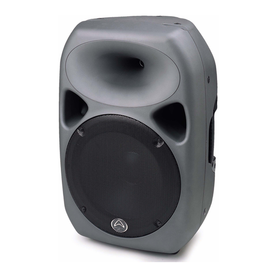
Titan 15 ACTIVE
IAG House, Sovereign Court, Ermine Business Park, Huntingdon, Cambs, PE29 6XU, England
The information in this s
ervice
m
anual
Service Manual
Wharfedale Professional
www.wharfedalepro.com
is subject to change without notice. All rights reserved
Professional Sound Systems
SCHEMATIC DIAGRAM
ELECTRONIC PARTS LIST
ELECTRONIC PARTS LIST
ELECTRONIC PARTS LIST
ELECTRONIC PARTS LIST
ELECTRONIC PARTS LIST
ELECTRONIC PARTS LIST
2008 Wharfedale Pro is a member of the International Audio Group
1
2
3
4
5
6
7
8
9
10
11
12
13
14
15
16
17
Advertisement
Table of Contents

Summary of Contents for Titan 15 ACTIVE
-
Page 1: Table Of Contents
Professional Sound Systems Titan 15 ACTIVE Service Manual SPECIFICATION SPECIFICATION ASSEMBLY SKETCH SCHEMATIC DIAGRAM SCHEMATIC DIAGRAM SCHEMATIC DIAGRAM SCHEMATIC DIAGRAM SCHEMATIC DIAGRAM SCHEMATIC DIAGRAM SCHEMATIC DIAGRAM ASSEMBLY PARTS LIST ELECTRONIC PARTS LIST ELECTRONIC PARTS LIST ELECTRONIC PARTS LIST ELECTRONIC PARTS LIST... -
Page 2: Specification
1.SPECIFICATIONS System Type Active 15 2-way Bi-Amplified system Frequency Response (+/-3dB) 50-20kHz Low Frequency Transducer Size (mm / inches) 381mm / 15" Coil Size (mm / inches) 75mm / 3.0" Impedance 4Ω High Frequency Transducer Type Compression Driver Coil Size (mm / inches) 51mm / 2"... -
Page 3: Specification
2.SPECIFICATIONS Input B % type Line level input Input Sensitivity XLR / 1/4" Combo jack: 1.78dBv or 1.228Vrms RCA: 0dBu (-2.2dBv or 0.775Vrms) Maximum Input Level +22dBu Combo jack: 1/4" - XLR / Summed dual RCA jacks Input Connectors Line Output Line Output Connector Switchable LOOP / MIX Balanced Male XLR Connector... -
Page 4: Assembly Sketch
3.ASSEMBLY SKETCH... -
Page 5: Schematic Diagram
4.SCHEMATIC DIAGRAM... - Page 6 5.SCHEMATIC DIAGRAM...
-
Page 7: Schematic Diagram
6.SCHEMATIC DIAGRAM... -
Page 8: Schematic Diagram
7.SCHEMATIC DIAGRAM... -
Page 9: Schematic Diagram
8.SCHEMATIC DIAGRAM... -
Page 10: Schematic Diagram
9.SCHEMATIC DIAGRAM... -
Page 11: Schematic Diagram
10.SCHEMATIC DIAGRAM... -
Page 12: Assembly Parts List
11.ASSEMBLY PARTS LIST PART NAME DESCRIPTION 313-2104900001R LOGO 310-2104900000R GRILLE 537-4001080801AR M4×8 SCREW 513-4012130800AR LEVEL 565-0534100000R COPPER NUT 537-5001250801AR M5×25 SCREW 565-0537100000R COPPER NUT ZD-70401-01R WOOFER 200-2105000003R BAFFLE 537-6001100801AR M6×10 SCREW 249-2010490001R PANEL 559-5001300071R M5*30 SCREW ZD-70100-01R TWEETER 500-1200951100R 274-0400900786R PLUG 321-4201202286R M12×M8×42... - Page 13 12.ELECTRONIC PARTS LIST PART NAME DESCRIPTION LOCATION 031-2200512121R FUSE 50T040H 042-1003005001R POWER SWITCH RF-1003TV-5AC250V 044-2600000000R POWER SOCKET RF-2004 055-0305006133R RIBBON CABLE 5PIN 24AWG UL1007 L=60mm RIBBON CABLE 055-0310025133R 10PIN 24AWG UL1007 L=250mm RIBBON CABLE 055-0402032311R 2pin 18AWG UL1617 L=320mm 055-0407005111R RIBBON CABLE 7PIN 18AWG UL1015 L=50mm 060-0180120300R...
- Page 14 13.ELECTRONIC PARTS LIST 008-1021040005R CAPACITOR 102PF 400V M C10.11.17.22 013-2240320503R CAPACITOR 220NF100V 7.5*5.0*8.0 ±5% 013-3304025005R CAPACITOR 334/275V J C16% 18 014-1040311028R CAPACITOR MKS2 100nF 100V 10% C21.31.32.81.99.100 014-1050411006R CAPACITOR 1UF/250V 10% 016-4741112201R CAPACITOR 0.47UF/100V P=15mm C56& 63.89.90 017-0190000000R NJM7815FA TO-220F(JRC) 017-1830000000R KIA7915 TO-220 KEC 017-2700000000R...
- Page 15 14.ELECTRONIC PARTS LIST R74.75.76.85.94.95.96. 002-1004032010R RESISTOR 100KΩ 1/8W 1% 0805 002-1502032050R RESISTOR 1.5K 0805 ±5% 1/8W 002-1504032050R RESISTOR 150K 0805 ±5% 1/8W 002-1603032050R RESISTOR 16K 0805 ±5% 1/8W R111 002-1800042050R RESISTOR 18R 0805 1/8W 1% R65.67 002-1803032010R RESISTOR 18K 1/8W 0805 1% R3.88 002-2003032010R RESISTOR...
- Page 16 15.ELECTRONIC PARTS LIST 088-1472525000R LED BOARD R113.115.117.119.121. 001-1002105050R RESISTOR 1K 1/4W J 019-0379132200R POWER LED φ3mm LED1& 6 053-1472511658R 64*64mm 1.6T 1OZ 055-1302044444R RIBBON CABLE L=440MM ±10 UL1007#26 CON8& CON9 088-1472525501R AMP BOARD 002-1002032010R RESISTOR 1K 1/8W 1% 0805 002-1003032010R RESISTOR 10KΩ...
- Page 17 16.ELECTRONIC PARTS LIST 017-1124000000R IR2153D DIP-8 IR 018-2800112115 R FIELD EFFECT TRANSISTOR J112G TO-92 019-0311122001R POWER LED 204HD/E-A RED φ3 LED7 019-0322122001R POWER LED LED 204GD/E-A GREEN φ3 LED8 020-1032120325R POTENTIOMETER RD16K12D0094-10K15Ax2 VR201.204 020-5052119425R POTENTIOMETER RD 16K124A068-50KCBX2SII VR-202.203 040-1400000000R SWITCH JPS2281EA SW201.201 048-3000000000R...
- Page 18 17.ELECTRONIC PARTS LIST 002-4702032010QR RESISTOR 4.7K 1/8W 1% 0805 R259.264 002-4703032010R RESISTOR 47KΩ 1/8W 1% 0805 R208.211.277.5B 002-5102032010R RESISTOR 5.1KΩ 1/8W 1% 0805 R273.274 002-5102032100R RESISTOR 51K±5%1/8W 0805 R249 002-5602032010R RESISTOR 5.6KΩ 1/8W 1% 0805 R20.279 002-6801032010R RESISTOR 680Ω 1/8W 1% 0805 002-6802032050R RESISTOR 6.8K 0805 ±5% 1/8W...
Need help?
Do you have a question about the 15 ACTIVE and is the answer not in the manual?
Questions and answers