Table of Contents
Advertisement
04/06
PLEASE READ THESE OPERATING INSTRUCTIONS CAREFULY
Misuse and abuse of these instruments cannot be prevented by any
printed word and may cause injury and or equipment damage. Please
follow all these instructions and measurement procedures faithfully and
adhere to all standard industry safety rules and practices.
The Professional's Choice
OPERATING INSTRUCTIONS
Model DM-4100A
DIGITAL MULTIMETER
®
2150 Joshua's Path, Suite 302
Hauppauge, New York 11788
1-800-645-5398 | 631-231-7050
Fax: 631-434-3128
Form # 414
Advertisement
Table of Contents

Subscribe to Our Youtube Channel
Related Manuals for Sperry instrument DM-4100A


Summary of Contents for Sperry instrument DM-4100A
-
Page 1: Operating Instructions
04/06 Form # 414 OPERATING INSTRUCTIONS Model DM-4100A DIGITAL MULTIMETER PLEASE READ THESE OPERATING INSTRUCTIONS CAREFULY Misuse and abuse of these instruments cannot be prevented by any printed word and may cause injury and or equipment damage. Please follow all these instructions and measurement procedures faithfully and adhere to all standard industry safety rules and practices. -
Page 2: Table Of Contents
CONTENTS SECTION TITLE PAGE Warranty Description Features Specifications Safety Rules Front Panel Controls Preparation for Use Unpacking and Contents Check Pre-Operation Procedure Battery Replacement Fuse Replacement Operation Voltage Measurements Current Measurements 12-13 Resistance Measurements Battery Test Measurements Diode Tests Non Contact Voltage (NCV) Tests Maintenance 10.1 Cleaning... -
Page 3: Warranty
ONE YEAR LIMITED WARRANTY Sperry Instruments, Inc. warrants that this Sperry instrument has been carefully tested, inspected and warranted for one (1) year from the date of purchase by the original end user, provided the instrument has not been misused, damaged due to negligence, neglect or unauthorized repair, abused or used contrary to the operating instructions. -
Page 4: Description
DESCRIPTION Sec. 1 This exceptional 3-1/2 digit handheld, digital multimeter has the capacity of reading up to 6 functions on up to 18 ranges. This DMM offers a powerhouse of measurement capability in a small self-contained housing. It is designed for the professional at work, in the field or in the laboratory. - Page 5 Storage Environment: -20° C to 60° C (-4 F to 140° F) at 80% relative humidity. Power Source: One (1) 9V Transistor Type Battery. (NEDA #1604). Power Consumption: 30mW typical Battery Life: 1000 hours typical with zinc carbon. Battery Indicator: "...
- Page 6 DC Current Range Resolution Accuracy (18°C to 28°C) Full Scale Burden Voltage 1µA ±(1.0% of rdg + 1D) 0.35V 20mA 10µA " " 200mA 100µA " " 10mA ±(2.0% of rdg + 3d) 0.70V Overload Protection: 0.5A/250V fuse on mA inputs 10A for 60 seconds on 10A input (unfused) Resistance Range...
-
Page 7: Safety Rules
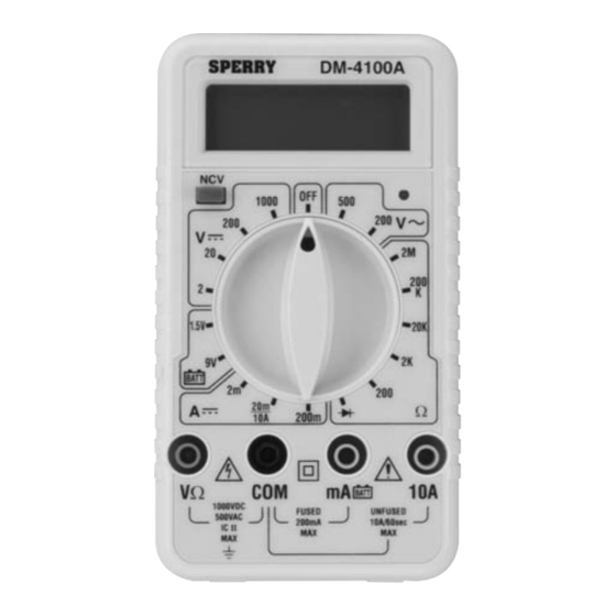
SAFETY RULES Sec. 4 1. Read these operating instructions thoroughly and completely before oper- ating your DMM. Pay particular attention to WARNINGS and CAUTIONS, which will inform you of potentially dangerous procedures. These instruc- tions must be followed. 2. Always inspect your DMM, test leads and accessories for any sign of damage or abnormality before every use. - Page 8 NCV Sensor End Digital Display Non Contact Voltage Function Range Selector Switch Input Terminals Fig. 1...
-
Page 9: Front Panel Controls
Sec. 6 UNPACKING AND CONTENTS CHECK Sec. 6.1 The DM-4100A comes complete and ready to use. Check the following contents list when unpacking. If any pieces are missing notify the distributor you purchased the instrument from or Sperry Instrument, Inc. -
Page 10: Battery Replacement
7. If any abnormal conditions exist, do not attempt to take any electrical measurements. Instead refer to sec. 14 Return for Repairs. BATTERY REPLACEMENT Sec. 7 The DM-4100A has a self-contained power supply consisting of One 9V Transistor Type Battery (NEDA #1604). - Page 11 WARNING Before attempting to replace the battery, first disconnect the test leads from any energized circuit and then disconnect the test leads from the instrument. 1. Disconnect the test leads from any energized circuit and then from the instrument. 2. Turn the range switch to the "OFF" position 3.
-
Page 12: Fuse Replacement
FUSE REPLACEMENT Sec. 8 A 0.5A, 250V, 5 x 20mm fast acting fuse, Part # F-17 is installed in the instru- ment and used to protect the ampere ranges (other than the 10A range) along with other solid state components. WARNING Before attempting to replace the fuse, disconnect the test leads from any energized circuit and then disconnect the test leads from the instrument. -
Page 13: Operation
OPERATION Sec. 9 Before making any measurements always examine the instrument and acces- sories used with the instrument for damage, contamination (excessive dirt, grease, etc.) and defects. Examine the test leads for cracked or frayed insula- tion and make sure the lead plugs fit snugly into the instrument jacks. If any abnormal conditions exist do not attempt to make any measurements. -
Page 14: Current Measurements
CURRENT MEASUREMENTS Sec. 9.2 1. Insert the black and red test leads into the respective "COM" and "10A" terminals. 2. Place the function switch to the 10A position. Always start with the highest range of the function to be measured. CAUTION The 10A range is unprotected and has a very low internal resistance. -
Page 15: Resistance Measurements
3. Raise the "COM" terminal potential above 500V to ground. 4. Energize the circuit. If the reading is within the next lower range, switch to that range after completely de-energizing the circuit under test. Continue changing to lower ranges if the reading is within the next lowest range to obtain the best accuracy. -
Page 16: Diode Tests
CAUTION To avoid electric shock, instrument damage and/or equipment damage. Do not exceed 10Vdc while set to take measurements in the battery test range. 3. Connect the test leads to the 1.5Vdc battery under test. Normally a good 1.5Vdc battery will read above 1.25Vdc. Consult the battery manufacturer for complete battery specifica- tions to determine actual battery life remaining and condition of battery... -
Page 17: Maintenance
MAINTENANCE Sec. 10 Maintenance consists of periodic cleaning, battery replacement, fuse replacement and recalibration. CLEANING Sec. 10.1 The exterior of the instrument can be cleaned with a soft clean cloth to remove any oil, grease or grime from the exterior of the instru- ment. -
Page 18: Calibration Procedure
CAUTION The following procedure should be performed by persons trained and qualified in electronics and electronic equipment service. DO NOT attempt this procedure if not qualified. WARNING Do not attempt calibration or service unless another person, capable of rendering first aid and resuscitation is present. Fig. - Page 19 Carefully inspect the other DCV ranges. Your readings should be within specification ±0.5% + 1 digit. There is no adjustment for ACV. Calibrate DCV first. Carefully inspect the ACV ranges. Your readings should be within ± 1.2% + 4 digits of the ACV calibration source. Set the output of the DC calibrator for 1.9 ±0.02% and connect it to the "10A"...
-
Page 20: Diagrams
DIAGRAMS Sec. 12 CIRCUIT DIAGRAM Sec. 12.1 Note: Subsequent revisions to this document may exist. Use for general references only. -
Page 21: Parts List
PARTS LIST Sec. 12.2 Size Part Description R001 R002 100J* R003 1/4WC R004 1/4WC R005 1/4WC R01 R02 274KF X2 1/4WC R03 R04 176KF X2 1/4WC 90KF 1/4WC 1/4WC 900F 1/4WC 100F 1/4W C R10,R98 47KJ X2 R11,R13,R20 110KJ X3 R12,R16,R19 1MJ X6 R41,R42,R43... - Page 22 10nF/25V 10uF/16V C40,C90 1uF/25V X2 330PJ D10,D11,D12,D13 1N4004 X4 1 N4007 D40,D90 1N4148 X2 LED (red) Zn 3.6VB SMD 1/2W 2SC2859 Q11,Q12,Q90,Q91 PN2222 X4 0.5A/250V PTC 2.2K 500V A/D 5106 4069 S0-8 BEEPER...
-
Page 23: Return For Repairs
RETURN FOR REPAIR Sec. 13 Before returning your digital Multimeter for repair be sure to check that the fail- ure to operate properly is not due to the following: 1. Weak battery 2. Open fuse 3. Open, loose or intermittent test leads. If these conditions do not exist and the instrument fails to operate properly return the instrument and accessories prepaid to: Sperry Instruments, Inc.
Need help?
Do you have a question about the DM-4100A and is the answer not in the manual?
Questions and answers