Table of Contents
Advertisement
OPERATOR'S MANUAL
MODEL #
HDS 2.0/10 Ed Cage / HPB-201107D
HDS 2.0/14 Ed Cage / HPB-201407D
HDS 2.5/10 Ed Cage / HPB-251007D
HDS 2.5/16 Ea Cage / HPB-251607A
HDS 3.5/20 Ea Cage / HPB-352007A
HDS 3.9/20 Ea Cage / HPB-392007A
To locate your local Kärcher Shark Commercial Pressure Washer Dealer nearest you,
visit www.karchercommercial.com or www.karchershark.com
ORDER #
1.575-500.0
HDS 3.5/30 Ea Cage / HPB-353007A
1.575-501.0
HDS 3.5/30 Eb Cage / HPB-353007B
1.575-502.0
HDS 3.5/30 Ec Cage / HPB-353007C
1.575-503.0
1.575-504.0
1.575-505.0
98000780-1
MODEL #
®
ORDER #
1.575-508.0
1.575-509.0
1.575-510.0
9.800-078.0
Advertisement
Table of Contents

Related Manuals for Karcher Shark HDS 2.0/10 Ed Cage


Summary of Contents for Karcher Shark HDS 2.0/10 Ed Cage
- Page 1 ® OPERATOR’S MANUAL 98000780-1 MODEL # ORDER # MODEL # ORDER # HDS 2.0/10 Ed Cage / HPB-201107D 1.575-500.0 HDS 3.5/30 Ea Cage / HPB-353007A 1.575-508.0 HDS 2.0/14 Ed Cage / HPB-201407D 1.575-501.0 HDS 3.5/30 Eb Cage / HPB-353007B 1.575-509.0 HDS 2.5/10 Ed Cage / HPB-251007D...
-
Page 2: Table Of Contents
CONTENTS Introduction & Important Safety Information Component Identifications Assembly Instructions Installation Operating Instructions Detergents & General Cleaning Techniques Shut Down & Clean-up Procedures Storage Troubleshooting 15-16 Maintenance Charts Oil Change Record Preventative Maintenance Maintenance & Service 18-20 1.575-500.0 Exploded View and Parts List 21-23 1.575-501.0, 502.0, 503.0, 504.0 Exploded View &... - Page 3 CONTENTS 1.575-501.0, 502.0, 503.0, 504.0 Auto Start/Stop - Steam Options Exploded View & Parts List 1.575-505.0, 506.0, 507.0, 508.0, 509.0, 510.0 Auto Start Stop - Steam Options Exploded View & Parts List 1.575-505.0, 506.0, 507.0, 508.0, 509.0, 510.0 Pump Assembly Exploded View & Parts List 1.575-501.0, 502.0, 503.0, 504.0 Steam Option Exploded View &...
-
Page 4: Introduction & Important Safety Information
INTRODUCTION & IMPORTANT SAFETY INFORMATION connected to a power supply receptacle protected Thank you for purchasing this Pressure Washer. by a GFCI. We reserve the right to make changes at any time DANGER: Improper connection of the equip- without incurring any obligation. ment-grounding conductor can result in a risk of Owner/User Responsibility: electrocution. -
Page 5: Important Safety Information
IMPORTANT SAFETY INFORMATION 10. Keep operating area clear of all persons. 14. Be cer tain all quick cou- WARNING pler fittings are secured be- WARNING: High pressure spray WARNING fore using pressure washer. can cause paint chips or other WARNING: High pressure particles to become airborne developed by these machines and fly at high speeds. - Page 6 IMPORTANT SAFETY INFORMATION 21. Do not operate this machine when fatigued or under the influence of alcohol, prescription medications, or drugs. Follow the maintenance instructions specified in the manual. HDS 500-510 • 9.800-078.0 • Rev. 4/10...
-
Page 7: Component Identifications
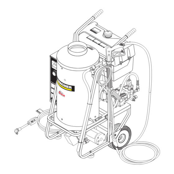
COMPONENT IDENTIFICATION - 1.575-500.0 Fuel Tank Fresh Water Faucet (not included) Wand Holder Burner Unloader Chamber Discharge Nipple GFCI Garden Hose (not included) Pump Rupture Disc High Limit Thermostat Nozzle Coupler Insulated Spray Gun Variable Pressure Insulated Wand Burner Motor Control 98000780-2 Handle... -
Page 8: Component Identification
COMPONENT IDENTIFICATION - 1.575-501.0 - 1.575-504.0 CAUTION HOT WATER: Must use insulated spray gun and wand. Fuel Tank Fresh Water Faucet (not included) Pump & Burner Switch Pressure Switch Control Panel High Limit Pump Unloader Thermostat Burner Chamber Garden Hose (not included) Discharge Downstream... - Page 9 COMPONENT IDENTIFICATION - 1.575-505.0 - 1.575-510.0 CAUTION HOT WATER: Must use insulated spray gun and wand. Quick Coupler Fuel Tank Discharge Nipple Burner Switch Pump Switch Detergent Pick-Up Hose Wand Holder High Limit Control Thermostat Panel Pressure Switch GFCI Pump Downstream Detergent Injector Unloader...
-
Page 10: Assembly Instructions
ASSEMBLY INSTRUCTIONS Fuel 98000780-5 STEP 1: Connect water supply STEP 2: Check fuel tank and STEP 3: Connect high pressure hose. pump oil levels. hose to discharge nipple by sliding quick coupler collar back. Insert quick coupler onto discharge nipple and secure by pushing quick coupler collar forward. -
Page 11: Installation
INSTALLATION Electrical: Place machine in a convenient location providing ample support, draining and room for maintenance. This machine, when installed, must be electrically This machine is intended for outdoor use. Machine grounded in accordance to local codes. Check for must be stored indoors when not in use. proper power supply using a volt meter. -
Page 12: Operating Instructions
OPERATING INSTRUCTIONS STEP 1: Turn water on. STEP 2: Connect the power cord STEP 3: Grip spray gun handle into the proper electrical outlet, then securely and pull trigger. Then turn push in the GFCI reset button. (Re- variable pressure control handle fer to serial plate for information). -
Page 13: Detergents & General Cleaning Techniques
DETERGENTS & GENERAL OPERATING TECHNIQUES WARNING: Some detergents pump protector engages and cools the pump by dis- WARNING may be harmful if inhaled or in- charging the warm water onto the ground. This thermal gested, causing severe nausea, device prevents internal damage to the pump. fainting or poisoning. -
Page 14: Shut Down & Clean-Up Procedures
SHUTTING DOWN AND CLEAN-UP STEP 1: Remove detergent suction STEP 2: Turn burner switch off and STEP 3: Turn off water supply. tube from container and insert into continue spraying water, allowing 1 gallon of fresh water. Turn variable the water to cool. After water has pressure wand handle for low pres- cooled to less than 100°F, turn the sure or connect the black detergent... -
Page 15: Troubleshooting
TROUBLESHOOTING PROBLEM POSSIBLE CAUSE SOLUTION LOW OPERATING Faulty pressure gauge Install new gauge. PRESSURE Insufficient water supply Use larger garden hose; clean filter washer at water inlet. Old, worn or incorrect spray Match nozzle number to machine and/or replace nozzle with new nozzle. - Page 16 TROUBLESHOOTING PROBLEM POSSIBLE CAUSE SOLUTION LOW WATER Improper fuel or water in fuel Drain fuel tank and replace with proper fuel. TEMPERATURE Low fuel pressure Increase fuel pressure. Weak fuel pump Check fuel pump temperature. Replace pump if needed. Fuel filter partially clogged Replace as needed.
-
Page 17: Maintenance Charts
MAINTENANCE CHARTS This pressure washer was produced with the best available materials and quality craftsmanship. However, you as the owner have certain responsibilities for the correct care of the equipment. Attention to regular preventative maintenance procedures will assist in preserving the performance of your equipment. Contact your Pressure Washers dealer for maintenance. -
Page 18: Preventative Maintenance
PREVENTATIVE MAINTENANCE 1. Use clean fuel — kerosene, No. 1 home heating essary. Store the machine in a heated room. If this is fuel or diesel fuel. Clean or replace fuel filter every not possible then mix a 50/50 solution of anti-freeze/ 100 hours of operation. -
Page 19: Rupture Disk
MAINTENANCE Electrode Setting - Wayne: Step 4 After circulating solution flush entire system with fresh water. (See illustration below) Removal of Soot In Heating Coil: 1/8" In the heating process, fuel residue in the form of soot 1/8" Electrodes deposits may develop between the heating coil pipe and block air flow which will affect burner combustion. -
Page 20: Fuel Pressure Adjustment
MAINTENANCE Fuel Pressure Adjustment: FUEL AIR ADJUSTMENT: WAYNE To adjust fuel pressure, turn the adjusting screw with a standard screwdriver (located on the fuel pump) clock- wise to increase, counterclockwise to decrease. Do not exceed 200 PSI. Air Band Air Adjustment Pressure The oil burner on this machine is preset for operation at Gauge Port... -
Page 21: 5-500.0 Exploded View And Parts List
EXPLODED VIEW - 1.575-500.0 8, 23 Burner Detail See Control For Detail See Steam Valve Options Illus. Optional Filter Upgrade 98000780-7 HDS 500-510 • 9.800-078.0 • Rev. 4/10... -
Page 22: Parts List
EXPLODED VIEW - 1.575-500.0 PARTS LIST ITEM PART NO. DESCRIPTION 9.800-006.0 Label, Hot/Caliente w/Arrows Warning 9.803-029.0 Tank Head Assy 9.802-904.0 Insulation, Top Head 9.802-825.0 Clip, Retaining U-Type 9.802-081.0 Tank, Fuel 6 Gal Blank 9.802-254.0 Hose, 1/4", Push-On, Fuel Line 12˝ 9.800-110.0 Label, Logo, Large 9.802-753.0... - Page 23 EXPLODED VIEW - 1.575-500.0 PARTS LIST ITEM PART NO. DESCRIPTION 9.802-141.0 Hose Barb, 1/4" x 3/8" Double 9.802-709.0 Bolt, 5/16" x 3/4" NC GR 5 CS ZN 9.802-804.0 Washer, 5/16", Flat, SAE 9.800-020.0 Label, Cold Water Inlet, HS 9.802-107.0 Fastener, Ratchet, Black Nylon 9.802-070.0 Grip, 1"...
- Page 24 EXPLODED VIEW - 1.575-501.0, 502.0, 503.0, 504.0 10, 17 For Detail See Steam Detail See Valve Control Options Panel Illus. Illus. To Fuel Tank Optional Filter Upgrade 98000780-8 HDS 500-510 • 9.800-078.0 • Rev. 4/10...
- Page 25 EXPLODED VIEW - 1.575-501.0, 502.0, 503.0, 504.0 ITEM PART NO. DESCRIPTION 9.800-002.0 Label, Use Only Kerosene 9.800-006.0 Label, "Hot/Caliente" with Arrows Warning 9.800-015.0 Label, Warn, Service Cord 9.800-021.0 Label, Hot Water Outlet 9.800-110.0 Label, Logo Large 9.800-035.0 Label, Warning (Lexan) For Motor, Please see specifications pages.
- Page 26 EXPLODED VIEW - 1.575-501.0, 502.0, 503.0, 504.0 ITEM PART NO. DESCRIPTION 8.902-433.0 Relief Valve USA 9.196-012.0 Screw, 10-24 x 1/4" 8.711-785.0 Hose, 3/8", Push-On 30" 9.803-029.0 Tank Head Assy. 16" x 8" 8.706-248.0 Plug, 3/8" 9.803-061.0 Axle, 5/8" x 25.710 9.802-782.0 Collar, 5/8"...
- Page 27 EXPLODED VIEW - 1.575-505.0, 506.0, 507.0, 508.0, 509.0, 510.0 18, 29, 84, 87 27, 41, 71 86, 69 Detail See Control Panel 75, 26 Illus. 14 8 Detail See Pump Illus. Detail See Steam Valve Options Illus. Optional Detail See Filter Optional Upgrade...
- Page 28 1.575-505.0, 506.0, 507.0, 508.0, 509.0, 510.0 PARTS LIST ITEM PART NO. DESCRIPTION 9.800-002.0 Label, Use Only Kerosene 9.800-006.0 Label, "Hot/Caliente" with Arrows Warning 9.800-015.0 Label, Warning, Service Cord 9.800-021.0 Label, Hot Water Outlet 9.800-110.0 Label, Logo Large 9.800-035.0 Label, Warning (Lexan) 9.802-066.0 Pad, Soft Rubber, 50 Duro 9.802-070.0...
- Page 29 1.575-505.0, 506.0, 507.0, 508.0, 509.0, 510.0 PARTS LIST ITEM PART NO. DESCRIPTION 8.719-935.0 Retainer Ring, Insulation 9.196-012.0 Screw, 10-24 x 1/4" 8.711-785.0 Hose, 3/8" Push-On 2.50 ft 9.802-212.0 Filter, Fuel/H 9.802-781.0 Nut, 3/8" Flange, Whiz Loc 9.803-264.0 Nipple, 1/4" x 3", Black Pipe 9.802-810.0 Washer, 5/8"...
- Page 30 1.575-505.0, 508.0, 509.0, 510.0 PARTS LIST ITEM PART NO. DESCRIPTION 9.800-032.0 Label, Motor Overload Reset (505.0) 9.802-436.0 Cord Service 10-3 (505.0) 41" 9.802-437.0 Cord Service 10-4 (509.0) 41" 9.802-425.0 Cord Service 8-3 (508.0) 41" 8.704-660.0 Label, Kärcher-Shark 9.802-793.0 Nut, Cage 1/4"...
-
Page 31: 5-500.0 Control Panel, Exploded View & Parts List
CONTROL PANEL - 1.575-500.0 4,11 (Reversed View of Label) CONTROL PANEL - 1.575-500.0 PARTS LIST ITEM PART NO. DESCRIPTION 9.800-016.0 Label, Disconnect Power Supply 9.802-759.0 Screw, 10/32" x 1/2" NHSOC, Black 9.802-449.0 Switch, 3 PS, 115V-230V, 1PH 9.802-285.0 Thermostat, Adjustable, 302°F 9.802-762.0 Screw, 10/32"... - Page 32 CONTROL PANEL - 1.575-500.0 PARTS LIST ITEM PART NO. DESCRIPTION 9.803-094.0 Electric Box Cover, Black 9.802-103.0 Bushing, Snap, 5/8" 9.800-040.0 Label, Ground 9.800-018.0 Label, Tipover Hazard 9.800-049.0 Label, Cleaning Solution 8.750-096.0 Knob, Thermostat 302°F 8.712-190.0 Bezel, Plastic 9.196-012.0 Screw, 10/24 x 1/4" Hex ...
-
Page 33: Exploded View & Parts List
CONTROL PANEL - 1.575-501.0, 502.0, 503.0, 504.0 34, 35 15, 16 CONTROL PANEL - 1.575-501.0, 502.0, 503.0, 504.0 PARTS LIST ITEM PART NO. DESCRIPTION For Fuse, Please see specifications pages. (503.0, 504.0) For Fuse, Please see specifications pages. (503.0, 504.0) 9.802-449.0 Switch, 3 PS, 115V-230V, 1 PH Salzer 9.802-299.0... - Page 34 CONTROL PANEL - 1.575-501.0, 502.0, 503.0, 504.0 PARTS LIST ITEM PART NO. DESCRIPTION For Transformer, Please see specifications pages. (503.0, 504.0) 9.802-880.0 Cover, Electrical Box, Black 9.800-016.0 Label, Disconnect Power 9.802-759.0 Screw, 10/32" x 1/2" (503.0, 504.0) (501.0, 502.0) 9.802-791.0 Nut, Cage, 10/32"...
-
Page 35: Exploded View & Parts List
CONTROL PANEL - 1.575-505.0, 506.0, 507.0, 508.0, 509.0, 510.0 35, 36 2, 8 1.575-505.0, 506.0, 507.0, 508.0, 509.0, 510.0 PARTS LIST ITEM PART NO. DESCRIPTION 9.802-451.0 Switch, Rocker, Carling w/Green Lens (Time Delay option) 9.802-452.0 Rocker Switch, Red Lens (Time Delay option) 9.802-447.0 ... - Page 36 1.575-505.0, 506.0, 507.0, 508.0, 509.0, 510.0 PARTS LIST ITEM PART NO. DESCRIPTION 9.802-303.0 Nozzle, SAQCMEG 0055, Red (505.0, 506.0, 507.0) 9.802-304.0 Nozzle, SAQCMEG 1505.5, Yellow (505.0, 506.0, 507.0) 9.802-305.0 Nozzle, SAQCMEG 2505.5, Green (505.0, 506.0, 507.0) 9.802-306.0 Nozzle, SAQCMEG 4005.5, White (505.0, 506.0, 507.0) 9.802-295.0 Nozzle, SAQCMEG 0004, Red (508.0, 509.0, 510.0) 9.802-296.0...
-
Page 37: Exploded View & Parts List
FLOAT TANK OPTION - 505.0, 506.0, 507.0, 508.0, 509.0, 510.0 Steam Option 1, 8 To Float To Float Tank Tank Auto Start/Stop Auto Start/Stop Option Steam Option ITEM PART NO. DESCRIPTION 9.802-085.0 Tank, Float 9.803-269.0 Shelf, Float Tank, Black 9.802-767.0 Screw, 3/8"... - Page 38 FLOAT TANK 505.0, 506.0, 507.0, 508.0, 509.0, 510.0 PARTS LIST ITEM PART NO. DESCRIPTION 9.803-265.0 Elbow, 1/2" Female, Brass 9.802-111.0 Nipple, 1/2" NPT, 5/16", Modified Close 9.802-043.0 Elbow, 1/2" x 1/2" Female, 90° 9.802-240.0 Hose, 3/8" x 22", 2 Wire, Pressure Loop 9.802-146.0 Swivel, 1/2"...
-
Page 39: Exploded View & Parts List
AUTO START/STOP OPTIONS 501.0, 502.0, 503.0, 504.0 AUTO START/STOP OPTIONS PARTS LIST 501.0, 502.0, 503.0, 504.0 ITEM PART NO. DESCRIPTION 9.802-146.0 Swivel, 1/2" MP x 3/4" GHF w/Strainer 9.802-117.0 Tee, 1/2" Female Pipe 9.803-989.0 Nipple, 1/2" Hex 9.802-127.0 Nipple, 1/2" JIC x 1/2" MPT Pipe 9.802-151.0 Swivel, 1/2"... -
Page 40: Auto Start/Stop Options Exploded View & Parts List
AUTO START/STOP OPTIONS 505.0, 506.0, 507.0, 508.0, 509.0, 510.0 AUTO START/STOP OPTIONS PARTS LIST 505.0, 506.0, 507.0, 508.0, 509.0, 510.0 ITEM PART NO. DESCRIPTION 9.802-146.0 Swivel, 1/2" MP x 3/4" GHF w/Strainer 9.802-117.0 Tee, 1/2" Female Pipe 9.803-989.0 Nipple, 1/2" Hex 9.802-127.0 Nipple, 1/2"... - Page 41 AUTO START/STOP - STEAM OPTIONS & PARTS LIST 501.0, 502.0, 503.0, 504.0 ITEM PART NO. DESCRIPTION 9.803-546.0 Hose, 3/8" x 18" Pressure Loop 9.802-146.0 Swivel, 1/2 x 3/4 GHF w/Strainer 9.802-123.0 Tee, 1/2" w/1/8" Hole Street 9.802-131.0 Elbow, 1/2" JIC x 1/2 - 90° 9.802-142.0 Hose Barb, 1/4 Barb x 1/8"...
- Page 42 AUTO START/STOP - STEAM OPTIONS & PARTS LIST 505.0, 506.0, 507.0, 508.0, 509.0, 510.0 ITEM PART NO. DESCRIPTION 9.802-240.0 Hose, 3/8" x 22" Pressure Loop 9.802-146.0 Swivel, 1/2 x 3/4 GHF w/Strainer 9.802-123.0 Tee, 1/2" w/1/8" Hole Street 9.802-131.0 Elbow, 1/2" JIC x 1/2 - 90° 9.802-142.0 Hose Barb, 1/4 Barb x 1/8"...
- Page 43 1.575-505.0, 506.0, 507.0, 508.0, 509.0, 510.0 PUMP ASSEMBLY 1.575-505.0, 506.0, 507.0, 508.0, 509.0, 510.0 PARTS LIST ITEM PART NO. DESCRIPTION 9.802-182.0 Pump Protector, 1/2" PTP 9.802-458.0 Pressure Switch, 1/4" 9.802-039.0 Elbow, 1/2" JIC x 3/8", 90° 9.802-146.0 Swivel, 1/2" GHF For Unloader, Please see specifications pages For Pump, Please see specifications pages 9.802-632.0...
- Page 44 501.0, 502.0, 503.0, 504.0 STEAM OPTION 501.0, 502.0, 503.0, 504.0 PARTS LIST ITEM PART NO. DESCRIPTION 9.802-143.0 Hose Barb, 1/4" Barb x 1/4" Pipe, 90° 6.390-126.0 Clamp, Hose, .46-, .54 ST 9.802-187.0 Valve, Flow Control w/Metering 9.802-010.0 Nipple, 1/4" Hex Steel 9.804.022.0 Cap, Valve with 1/4"...
- Page 45 1.575-505.0, 506.0, 507.0, 508.0, 509.0, 510.0 STEAM OPTIONS 1.575-505.0, 506.0, 507.0, 508.0, 509.0, 510.0 PARTS LIST ITEM PART NO. DESCRIPTION 9.802-143.0 Hose Barb, 1/4" Barb x 1/4" Pipe, 90° 6.390-126.0 Clamp, Hose, .46-, .54 ST 9.802-187.0 Valve, Flow Control w/Metering 9.802-010.0 Nipple, 1/4"...
- Page 46 HOSE & SPRAY GUN ASSEMBLY Pressure Nozzle HOSE & SPRAY GUN ASSEMBLY PARTS LIST ITEM PART NO. DESCRIPTION 9.802-165.0 Coupler, 1/4" Male 9.802-096.0 Quick Coupler O-Ring, Small 9.802-286.0 Nozzle Only, 1/8" Soap 9.802-222.0 Wand, Zinc, VP, w/Coupler 9.803-267.0 ...
- Page 47 UU1 UNLOADER VALVE EXPLODED VIEW 9.175-018.0, 3500 PSI Universal Unloader UU1 UNLOADER VALVE EXPLODED VIEW PARTS LIST ITEM PART # DESCRIPTION KIT QTY ITEM PART # DESCRIPTION KIT QTY 9.149-006.0 Sliding Connector Guide Piston Housing O-Ring Back up Piston Conical Seal 8.749-795.0 Piston O-Ring Back up 8.749-796.0...
- Page 48 KE.1 SERIES PUMP EXPLODED VIEW 9.803-814.0 KE 2020F.1 9.803-815.0 KE 2020S.1 9.803-816.0 KE 2825F.1 9.803-817.0 KE 2825S.1 9.803-818.0 KE 3525F.1 TORQUE SPECS Item # Ft.-lbs KE.1 SERIES PUMP EXPLODED VIEW PARTS LIST ITEM PART NO. DESCRIPTION ITEM PART NO. DESCRIPTION 9.803-938.0 Crankcase 9.803-951.0 Brass Plug G1/4 9.804-586.0 Plunger Oil Seal...
- Page 49 KE.1 SERIES PUMP PARTS LIST (CONT) ITEM PART NO. DESCRIPTION 9.804-584.0 Flange Screw 9.804-585.0 Crankshaft Seal See Kit Plunger Nut See Kit Copper Spacer See Kit Plunger 15mm (2020F, 2825F, 3525F) See Kit Plunger 18mm (2020S, 2825S) See Kit Copper Spacer See Kit O-Ring Ø1.78 x 5.28 See Kit...
- Page 50 KM.2 PUMP EXPLODED VIEW 9.803-405.0 KM4030R.2 9.803-406.0 KM4030L.2 9.802-343.0 KM4035R.2 9.803-407.0 KM4035L.2 9.802-342.0 KM5030R.2 9.803-408.0 KM5030L.2 8.749-940.0 KM6035R.2 8.749-941.0 KM6035L.2 8.904-689.0 KM3540R.2 TORQUE SPECS Item # Ft.-lbs KM.2 PUMP EXPLODED VIEW PARTS LIST ITEM PART NO. DESCRIPTION ITEM PART NO. DESCRIPTION 8.717-130.0 Crankcase...
- Page 51 KM.2 PUMP EXPLODED VIEW PARTS LIST (CONT) ITEM PART NO. DESCRIPTION 9.803-144.0 Plunger Rod 9.803-158.0 Connecting Rod 9.802-913.0 Snap Ring 9.802-916.0 Connecting Rod Pin 9.803-218.0 Spring Washer 9.803-238.0 Connecting Rod Screw 8.933-016.0 O-Ring, Ø2.62 x 126.67 9.803-165.0 Crankcase Cover 9.803-197.0 O-Ring, Ø1.78 x 14 9.803-202.0 Sight Glass 3/4...
- Page 52 SPECIFICATIONS MOTOR PUMP Machine Pump Pump Unloader Unloader Pulley Motor Motor Pulley Part # Model Parts# Replacement Production Pulley Part # Size Voltage Part # Pulley Part # 1.575-500.0 KE2020F 9.803-814.0 9.175-018.0 9.175-016.0 1.5 HP 120v/1ph/60Hz 9.802-338.0 1.575-501.0 KE2020F 9.803-814.0 9.175-018.0 9.175-016.0 2 HP 120v/1ph/60Hz 9.802-339.0...
- Page 53 SPECIFICATIONS CONTROLS MOTOR Model Bushing Belt Belt Motor Stepdown Primary Second Part # Bushing Part # Size Part # Contactor Overload Transformer Fuse Part# Fuse Part# 500.0 501.0 502.0 503.0 9.802-551.0 9.802-461.0 9.802-463.0 504.0 9.802-551.0 9.802-461.0 9.802-463.0 505.0 Hx1-1/8" 9.802-400.0 AX 34(2) 9.802-407.0 8.724-281.0...
-
Page 54: Burner Specifications
BURNER SPECIFICATIONS Burner Burner Fuel Pump/ Fuel Model # Assy # Fuel Nozzle Transformer Motor Solenoid/Cord Solenoid Coil Electrode 1.575-500.0 9.802-558.0 9.802-583.0 9.802-647.0 9.802-642.0 9.802-645.0 9.802-640.0 9.802-570.0 1.575-501.0 9.802-555.0 9.802-583.0 9.802-647.0 9.802-642.0 9.802-645.0 9.802-640.0 9.802-570.0 1.575-502.0 9.802-558.0 9.802-584.0 9.802-647.0 9.802-642.0 9.802-645.0 9.802-640.0 9.802-670.0... - Page 55 LIMITED NEW PRODUCT Phone: 360-833-1600 ® WARRANTY—COMMERCIAL fax: 800-248-8409 PRESSURE WASHERS www.karchercommercial.com WHAT THIS WARRANTY COVERS All Kärcher commercial pressure washers are warranted by Kärcher to the original purchaser to be free from defects in materials and workmanship under normal use, for the periods specified below. This Limited Warranty, subject to the exclusions shown below, is calculated from the date of the original purchase, and applies to the original components only.
- Page 56 ® www.karchercommercial.com www.karchershark.com Form HDS 500-510 # 9.800-078.0 • Revised 4/10 • Printed in U.S.A. or Mexico...
Need help?
Do you have a question about the HDS 2.0/10 Ed Cage and is the answer not in the manual?
Questions and answers