
Summary of Contents for Green eco Therm Pelletherm v2
- Page 1 USER MANUAL of hot water pellet boiler of series “Pelletherm v2” http:// www.greenecotherm.eu...
- Page 2 IN CASE THAT REQUIREMENTS, DEPICTED IN THIS MANUAL ARE NOT SATISFIED, FAILURES OF THE UNIT COULD BE EXPECTED, OR EVEN FATAL CONSEQUENCES, FOR WHICH THE PRODUCER COMPANY DOES NOT TAKE RESPONSIBILITY. Hot water pellet boiler of series “Pelletherm v2” user manual ; (document version: 31.10.2011 15:51) p. 2/52...
-
Page 3: Table Of Contents
............. 11 Table 2.5 ENplus - European standard for wood pellets; ....... 12 Description of hot water pellet boiler of series “Pelletherm v2”..13 Installation process................. 17 4.1. Hot water pellet boiler connection methodology ....... 20 4.1.1. - Page 4 Operation faults and their repairing ..........43 5.9. Hot water boiler warranty form completion........46 5.10. Actions, after the unit is not in exploitation anymore...... 46 Electrical scheme of automatic pellet boiler of series “Pelletherm v2”........................47 QUALITY CERTIFICATE ................49 WARRANTY FORM..................
-
Page 5: Properties And Advantages
1. Hot water pellet boiler of series “Pelletherm v2” – description, properties and advantages. “Pelletherm v2” is steel-plate hot water pellet boiler, which uses solid biomass fuel in shape of pellets. The boiler is designed to be connected to local hot-water heating systems, as well as heating up domestic hot water. -
Page 6: The Unit Is Equipped With
The unit is equipped with: • Steel plates welded heat exchanger for heating-up the circuit water; • Flue gas fan; • Fresh air supplying fan; • Burner’s ash removal mechanism – removes the ash residuum out of the burner’s grate; •... - Page 7 • The boiler is automatic and the thermal comfort achieved is close to that, originating from exploitation of fully automatic boilers, (for example liquid or gas fuel, as well as electric boiler), which makes is applicable in heating systems, equipped with programmable room thermostat; •...
- Page 8 Hot water boiler of series v2” technical data. • Thermal and technical data for hot water pellet boiler of series “Pelletherm v2”, utilizing wood pellets are given in Table 2.1; • Dimensions and technical data for hot water pellet boiler of series “Pelletherm v2”...
-
Page 9: Table 2.1 Thermal And Technical Data For Hot Water Pellet Boiler Of Series Pelletherm V2", Utilizing Wood Pellets
The quantity depends on the ash contents in the raw Solid fuel residue fuel, as well as operating conditions Table 2.1 Thermal and technical data for hot water pellet boiler of series “Pelletherm v2”, utilizing wood pellets. p. 9/52... - Page 10 Parameter Dimension Value Pelletherm Pelletherm Model of the hot water boiler 30v2 45v2 Weight Water jacket capacity dm³ Fuel hopper capacity dm³ 100 kg wood pellets Overall dimension of the unit 1515 x 850 x 1618 x 850 (WxDxH) 1375 x 1380 Class (according to EN 303-5)
-
Page 11: Table 2.3 Recommended Solid Fuel Properties – Wood Pellets
Parameter Dimension Value Pellet’s characteristic size 6 – 14 Recommended fuel net calorific value (low MJ/kg >17.2 heating value) kWh/kg >4.7 Wood pellet class ENplus-A1, ENplus-A2, ENplus-B Wood pellets category A, AB, B, BC, C, CD, E, EF Ash content See Table 2.4. -
Page 12: Table 2.5 Enplus - European Standard For Wood Pellets
The European wood pellets standard EN 14961-2:2010 defines wood pellets certificate ENplus for pellets, utilized in boilers and appliances for domestic heating systems. The certificate EN-B is applied for pellets, utilized in industrial boilers. In principal the ENplus standard defines two quality classes: А1 и... -
Page 13: Description Of Hot Water Pellet Boiler Of Series "Pelletherm V2
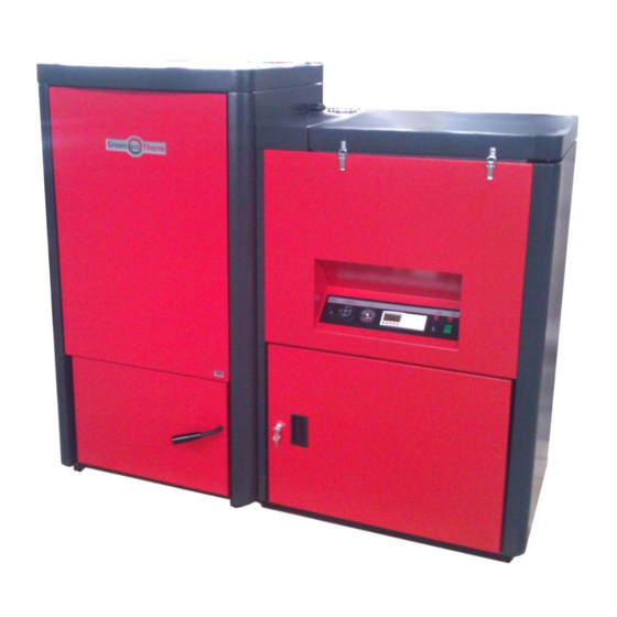
Description of hot water pellet boiler of series “ Pelletherm v2”. The heat exchanger of the boiler complies with the acting requirements for such kind of units, defined in operating norm : EN 303-5/2000 – „Heating boilers for solid fuels, hand and automatically fired, nominal heat output up to 300 kW. - Page 14 • Outer decorative covers are carbon steel plates color painted details; Figure 3.1 External view of hot water pellet boiler of series “Pelletherm v2”; The unit is designed and assembled in two main modules – the heat exchanger (the left one) and the fuel hopper module (the right one).
- Page 15 Figure 3.2 Partly sectioned view of hot water pellet boiler of series “Pelletherm v2” – front view; Flue gases exit duct External fuel delivery orifice Figure 3.3 External view of hot water pellet boiler of series “Pelletherm v2” – top view; p. 15/52...
- Page 16 Tertiary pass of flue gasses Secondary pass of flue gasses Primary pass of flue gasses Specialized pellet burner, equipped with ash cleaning mechanism Ash container Figure 3.4 Cross section view of hot water pellet boiler of series “Pelletherm 30 v2”. The flue gasses duct and streamlines are visualized as well; Tertiary pass of flue gasses Secondary pass of...
-
Page 17: Installation Process
• Installation and service procedures of solid fuel hot water boilers should be performed by authorized qualified and certified personal ONLY; • The hot water pellet boiler of series “Pelletherm v2” should be connected to heating system, supplied with OPENED or CLOSED expansion vessel. - Page 18 Figure 4.1 Positioning of hot water pellet boiler of series “ Pelletherm v2” – the minimal distances between the unit and any walls/obstacles of the boiler’s room are shown;...
- Page 19 The recommended principal hydraulic scheme for connecting the hot water pellet boiler of series “Pelletherm v2” to the heating system is snow on the following figure. Cold tap water To heating system Domestic hot water From heating system Tap water drainage Figure 4.2.
-
Page 20: Hot Water Pellet Boiler Connection Methodology
NOTE : According to EN 303-5 the heat accumulator is obligatory module of a heating system, equipped with solid fuel hot water boiler. The dimensioning of the heat accumulator tank is described in the above mentioned standard. The boiler producer could assist in appropriate designing of that module as well. 4.1. - Page 21 Figure 4.3. Back side view of heat exchanger connections of hot water pellet boiler “Pelletherm 30 v2”; p. 21/52...
- Page 22 Figure 4.4. Back side view of heat exchanger connections of hot water pellet boiler “Pelletherm 45 v2”; p. 22/52...
-
Page 23: Hot Water Boiler Installation And Starting Procedures
Hot water boiler installation and starting procedures. ATTENTION : The unit should be installed, adjusted and verified ONLY by trained and authorized staff. 5.1. Basic fuel requirements. • The fuel, pellet shaped, should be dry. The unit producer recommends that the fuel should be stored in dry and well ventilated rooms;... -
Page 24: 5.2. Starting Hot Water Pellet Boiler Of Series "Pelletherm V2" Procedure
5.2. Starting hot water pellet boiler of series “Pelletherm v2” procedure. Basic requirements: • Any maintenance procedures should be performed in accordance with the described in this manual;... -
Page 25: Interface Control Board Of Hot Water Pellet Boiler Of Series Pelletherm V2
Emergency thermostat switch Figure 5.1. Interface control board, equipped with control and operating devices of hot water pellet boiler of series “Pelletherm v2”. Interface control board devices description: • Main “POWER” switch – switches ON and OFF the main power supply of the boiler;... -
Page 26: Hot Water Boiler Power Supply
• Thermo-manometer – indicates the operating temperature of the circulating water in the heat exchanger jacket of the boiler, well as water overpressure; • “START” switch – sends “START/STOP” signal to the process control module, which controls the operation of the boiler; •... -
Page 27: Main Parameters For Boiler Operation
ATTENTION : During the operation of the boiler when the door of the combustion chamber is opened, it is possible to observe smoke leakage through the transport auger tract as well as the pellet hopper. Because of these reasons the opening of that door is not recommended. The same processes could be observed at the transition periods –... - Page 28 range. That’s why if any parameter is changed, it’s value should be checked and verified to lie in the appropriate limits. Special care should be taken to fulfill the following requirements: the ratio of the described periods T4 and T6 - (Т4/Т6) should be in the following range : •...
- Page 29 Ignition attempts counter (C- (EXPLANATION : at С=4 count the boiler makes 3 (three) ignition attempts); Table 5.2 Description of the control parameters, which define nominal operating mode of the hot water boiler of series “Pelletherm v2”. p. 29/52...
- Page 30 The above mentioned requires appropriate testing and verification of the fuel’s applicability as energy source for the hot water pellet boiler of series “Pelletherm v2” before making nominal exploitation of the unit. Consult the requirement for fuel of the boiler or the appliance producer’s assistance;...
-
Page 31: Adjustment Process Of The Boiler According To The Thermal Load Of The Building/Consumer
o Any other thermal capacity of the boiler is calculated, following the described procedure above – for example if the fuel has different calorific value or the required thermal capacity is lower, than the nominal one; The producer reserves the right to make changes of the setting of the process control module without obligations to inform the clients for that process;... - Page 32 ΔТ= Т – Т - temperature gradient, [ room ambient air Т ΔТ Ratio Т4* Heat Т6 ambient air T4/T6 capacity seconds seconds 0.85 17.0 45.0 0.68 13.6 36.0 0.51 10.2 27.0 0.26 13.5 Table 5.4. Appropriate adjustments of “heat capacity” parameters Т4 and Т6 according to the thermal load of the boiler “Pelletherm 45 v2”;...
- Page 33 Pellet’s feeding Ratio T4/T6 time, [seconds] 1.0900 21.000 0.9900 19.000 0.8900 17.000 0.7900 15.000 0.6900 0.5900 13.000 0.4900 11.000 0.3900 9.000 0.2900 7.000 0.1900 5.000 0.0900 9.00 18.00 24.00 30.00 9.00 18.00 24.00 30.00 Heat capacity of the boiler, [kW] Figure 5.2.
-
Page 34: Module
5.2.6. Changing the working parameters of the process control module. Algorithm for changing the value of working parameters of the process control module of the boiler: The following text describes algorithm for changing the values of any parameter of the process control unit (in case it is necessary !). It’s recommended to change these parameters only when it is necessary. - Page 35 8. Press the green button Menu/OK once more time and the process control module will exit the “PARAMETER” mode and will display the nominal operation process of the boiler control. NOTE: If any accidental change of a parameter has been made at the exit of this process a summary question will be displayed “CONFIRM CHANGES?”...
- Page 36 For example, if the user tried to get into other submenu, like “MONITORING”, then the controller will expect password entry, as described on the following figure: PASSWORD CLEAR 0/5 0000 5 = maximal number of trials for password entry SHIFT + OK = EXIT Figure 5.5.
-
Page 37: Nominal Operation Mode Of The Boiler
5.2.7. Nominal operation mode of the boiler. After successful ignition of the fuel and when the operating temperature of circulating water is stable it could be assumed that the hot water heating boiler is in nominal thermal load. This mode should be utilized in order to make adjustments of the operating parameters of the unit. -
Page 38: Adjustment Of The Thermal Capacity Of The Boiler
• In case that continuous operation in low thermal load regimes are required, then it is recommended to connect heat accumulator to the heating system, which will ensure high efficiency, economical and reliable operation of the boiler itself, and the entire heating system in general;... -
Page 39: Increasing The Thermal Capacity Of The Boiler
5.3.2. Increasing the thermal capacity of the boiler: It is realized by increasing the value of parameter Т4, which will result in increasing the fuel flow rate (fuel consumption). The same result (increasing the thermal capacity) is achieved by decreasing the value of parameter Т6. -
Page 40: Turning Off The Boiler
Completing these requirements will ensure long exploitation duration of the boiler and its high efficiency and reliability. 5.5. Turning OFF the boiler. The hot water boiler is turned off by changing the “START” switch into OFF position - this is the recommended method for turning the boiler off. During the working process in OFF state, the control module of the boiler performs so called “controlled turning off procedure”... -
Page 41: Showing And Teaching The End User About The Maintenance And Adjustment Procedures
Safety and unexpected risks Risks could arise at the exploitation of the boiler: The hot water pellet boiler of series “Pelletherm v2” is designed according to the safety requirements of the operating European standards and norms. However safety and unexpected risks could arise in situations like following: •... - Page 42 Unexpected risks: The unit is designed and produced according to the requirements of the operating EU safety norms. However, in spite of that possible risks are considered as a result of the operating process of the boiler, it is possible to get risks as follows: •...
-
Page 43: Operation Faults And Their Repairing
5.8. Operation faults and their repairing Operation fault Cause Method for repairing Low temperatures Insufficient heat Adjustment of operating parameters heat capacity is required – this should be supplied rooms performed by authorized technician set-point It is necessary to increase the set- temperature point of the boiler’s operating boiler’s... - Page 44 operation of the installation – this should heating performed authorized installation technician. After the boiler is cooled down ambient temperature and the reason for boiler overheating is serviced out, the protective cap of the emergency overheating thermostat should be unscrewed, its rod should be pressed until the thermostat is reset and it’s cap should be screwed back.
- Page 45 “opaque” pellets most probably the moisture content smoke is observed is higher than required; at the exit of the Inappropriate necessary perform chimney operating adjustment operating parameters parameters of the unit and achieve adjustment efficient combustion process - the adjustment should be performed by authorized technician;...
-
Page 46: Hot Water Boiler Warranty Form Completion
Table 5.4 Description of operation faults of the hot water boiler of series “Pelletherm v2”, causes and methods for repairing. 5.9. Hot water boiler warranty form completion. The applied WARRANTY FORM should be completed, by filling the required information in the appropriate fields. -
Page 47: 6. Electrical Scheme Of Automatic Pellet Boiler Of Series "Pelletherm V2
220 V Motors, transformer, thermostats, 40 VA Fuse2 + (12 - 14)V - Pw Fuse1 (12- 14V - Pw) Figure 6.1 Electrical scheme for connecting the automatic pellet boiler of series “Pelletherm v2” to the main power supply; p. 47/52... - Page 48 Feed External pellet transport-option Flue gas Actuator green +24 V-St 1К 1” & 2” black yellow Figure 6.2 Electrical scheme of the control board of hot water pellet boiler of series -12V -24 V-St -24 V-St “Pelletherm v2” p. 48/52...
- Page 49 Attachment and assembly of the elements, detached at the ash cleaning procedure..................14 3. Recommendations and requirements ............14 http:// www.greenecotherm.eu ANNEX 1 Hot water pellet boiler of series “Pelletherm v2” end-user maintenance procedures (Document edition : 16.11.2011 12:59) p. 1/14...
-
Page 50: General Principals
1. General principals The fuel of the hot water pellet boiler of series “Pelletherm v2” is wood pellets (or any other, verified and described in the user manual of the boiler) and the residual of the combustion process is mineral ash. The quantity of the ash depends on the fuel mineral mass content, i.e. -
Page 51: How To Stop The Operation Mode Of The Hot Water Boiler
Figure 2.1. Working gloves and working apron, provided for easy and safe cleaning process of the ash residue. 2.1. How to stop the operation mode of the hot water boiler The nominal operation of the boiler should be stopped by switching off the “START”... -
Page 52: Cooling Down The Boiler
2.3. Cooling down the boiler After the boiler is switched off it should be cooled down – it is necessary to wait until the temperature of the circulating water is moderate and the heat exchanging surfaces are cooled down to safe levels and the ash cleaning procedure could start. - Page 53 Figure 2.3. The flue gases duct lid is detached (the ash residue is clearly seen on the boiler’s heat exchanger surfaces); Utilize appropriate tool to clean (to grate) the ash and char deposition off the internal surfaces of the boiler’s body. ATTENTION : the practice shows that the ash grating is connected with intensive release of fly ash, thus it is highly recommended to wear air breathing protective mask as well as appropriate clothing in order to...
- Page 54 Figure 2.4. Ash deposits cleaning; Figure 2.5. Brushing the ash layer of the heat exchanger surfaces; The next step of the cleaning procedure is to clean the ash deposits on the third part of the flue gases duct of the boiler. p.
- Page 55 Figure 2.6. Cleaning the ash deposits off the heat exchanger surfaces, as well as off the ash cleaning mechanism; The ash should be thoroughly cleaned off the metal parts (of the cleaning mechanism and the heat exchanger as well). p. 7/14...
- Page 56 EXPLANATION : the ash particles, laid on the horizontal surface of the heat exchanger (at the flue gas pipes side) could be cleared by a specialized vacuum cleaner or it could be swept down through the pipes to the surfaces underneath –...
- Page 57 Figure 2.8. Detaching the front panel of the heat exchanger; The next step is to unscrew the fixing nuts of the lid, which closes the secondary ash deposition zone of the three way flue gas duct of the heat exchanger. Notice that the lid is tightened in order to prevent and flue gases leakage or ambient air both in and out of the flue gas duct.
- Page 58 Figure 2.10. Cleaning of the ash in the secondary deposition zone of the heat exchanger (right beneath the pipes of the heat exchanger); EXPLANATION : it is recommended to position the ash hopper in a position, which will allow easy collecting of the ash residue; The next step is to clean the ash and char residue, deposited in the burner.
- Page 59 EXPLANATION : the lid of the burner is freely mounted and no fixing items are used. It is positioned by special locking pins, fixed to the lower part of the burner in its front side. Figure 2.12. Ash and char cleaning procedure of the material, laid on the burner’s grate;...
- Page 60 After the burner’s grate has been thoroughly cleaned, it is necessary to clean the ash beneath the grate. EXPLANATION : the burner’s grate is detached by lifting and alongside pulling action. It is possible to have difficulties when detaching the grate due to the deposited ash and eventually any thermal deformation of the details.
- Page 61 Figure 2.15. Cleaning the ash residue, fallen beneath the grate of the burner; The next steps is to take away the ash hopper, placed on the bottom of the combustion chamber, to deposit away the ash residue in special fire protected container.
-
Page 62: Attachment And Assembly Of The Elements, Detached At The Ash Cleaning Procedure
2.5. Attachment and assembly of the elements, detached at the ash cleaning procedure The attachment procedure should be done in reverse sequence of the steps, depicted in the previous sections of the manual. ATTENTION: it is necessary to ensure air-tightness if the lids of the flue gases duct of the boiler (these are the lid of the ash deposition secondary zone, as well as the top lid, covering the flue gases duct of the heat exchanger), in order to ensure high reliability and efficiency of the appliance.
Need help?
Do you have a question about the Pelletherm v2 and is the answer not in the manual?
Questions and answers