Table of Contents
Advertisement
Advertisement
Table of Contents

Summary of Contents for Uniflair UST500
- Page 1 UNIFLAIR Instruction manual UST500 CONTROL BOARD...
- Page 2 UST500 CONTROL BOARD UNIFLAIR SpA policy is one of continuous technological innovation. The Company therefore reserves the right to amend any data herein without prior notice. Disposal: the product is made up of metal parts and plastic parts. In reference to European Union directive 2002/96/EC issued on 27 January 2003 and the related national legislation, please note that: •...
-
Page 3: Table Of Contents
UST500 CONTROL BOARD CONTENTS HOW TO USE THIS MANUAL ............................... 6 INTRODUCTION .................................... 7 General Description ......................................7 Typical applications: ......................................7 Technical data: ........................................ 7 Main functions: ........................................ 7 Models and Features ....................................... 7 USER INTERFACE (FOLDER PAR/UI) ............................8 Keys .......................................... - Page 4 UST500 CONTROL BOARD INTERNAL CIRCUIT PUMP (FOLDER PAR/PI) .......................... 45 Operating modes ......................................46 Antifreeze operation with pump ..................................47 EXTERNAL EXCHANGER FAN (FOLDER PAR/FE) ........................48 Configuration of fan ....................................... 48 Fan control in defrost ..................................... 50 INTERNAL EXCHANGER ELECTRIC HEATERS (FOLDER PAR/HI) ..................52 Internal exchanger heaters for antifreeze ...............................
- Page 5 UST500 CONTROL BOARD Reset alarm log (folder EUr) ..................................92 MECHANICAL ASSEMBLY ................................. 93 TECHNICAL DATA ..................................94 I/O features ........................................94 Mechanical specifications ....................................95 Display and LEDS ......................................95 Serials ........................................... 95 Transformer ........................................95 Mechanical dimensions ....................................95 DEVICE OPERATION ..................................
-
Page 6: How To Use This Manual
UST500 CONTROL BOARD How to use this manual This manual is designed to permit quick, easy reference with the following features: References References column: A column to the left of the text contains references to subjects discussed in the text to help you locate the information you need quickly and easily. -
Page 7: Introduction
Introduction General Description Uniflair SpA, a leading manufacturer for over a decade of control equipment for small and medium-size air conditioning units is proud to present UST500, the new range of compact devices with advance functions and groundbreaking applications. Single-circuit control of centralized air-conditioning systems with 1 or 2 compressors (steps) such as: •... -
Page 8: User Interface (Folder Par/Ui)
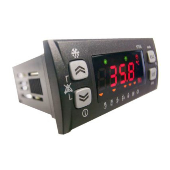
UST500 CONTROL BOARD User Interface (folder PAr/UI) The front panel of the device functions as the user interface and is used to perform all operations relating to the device. <IMG INF O> 226,75 117,6 99,25 Keys There are 4 keys on the front panel. Each key has (see the two tables below): A “direct”... -
Page 9: Local On/Off
226,65 Device ‘OFF’ --> ‘On’ The word OFF will appear on the display. Press the [DOWN] key for about 3 seconds UST500 will return to the “normal” screen <IMG INF O> 226,65 NOTE: The local ON/OFF function is deactivated if the device has been turned OFF remotely or if a digital input is configured as a remote ON/OFF. -
Page 10: Keys - Combined Action
UST500 CONTROL BOARD Keys – combined action Symbol Combined [function pressing associated to Combination of keys Press the combined Keys once [associated function] [Menu] / Comments pressing of (press and the keys] release [Manual reset] See Manual alarm (UP) acknowledgment and... -
Page 11: Leds And Display
UST500 CONTROL BOARD ALARM/ERROR ACKNOWLEDGMENT An error can be acknowledged by pressing any key once. After pressing any key, the alarm LED will start to blink. MANUAL RESET To manually reset an alarm, press the “up” and “down” keys together [UP+DOWN] - - - - - - - - - N.B: resetting an active alarm* will save the... -
Page 12: Led: States And Operating Modes
UST500 CONTROL BOARD LED: States and Operating Modes LED states and Operating Icon Colour Colour Permanently Blinking Modes Alarm Active alarm Alarm acknowledged Antifreeze with heat pump active Heating Heating mode Remote heating mode The display shows the value/resource set for the “main... -
Page 13: First Switch On
External exchanger fan LED 7 Internal circuit water pump First switch on When UST500 is switched on for the first time, a lamp test is carried out to check the state and proper function of lamps. ---------- The Lamp Test lasts for a few seconds. During this short time, all LEDs and digits flash at the same time. - Page 14 UST500 CONTROL BOARD All menus and labels are listed in the table below: MENU Di01 Di02 … Di05 … Main Display HOUr dAtE YEAr … Setr HEAt Operating mode COOL StdBY … States HOUr dAtE YEAr … CP01 CO02 PU01...
-
Page 15: Main Display" Menu
‘Main Display’ refers to the contents of the default display, i.e. when keys are not used. In UST500, the main display can be customized to suit personal requirements. The various contents can be selected from the “disp” menu which is opened by pressing and holding the [set] key for more than 3 seconds. The main display can be selected from: •... -
Page 16: Operating Mode" Menu
UST500 CONTROL BOARD “Operating Mode” menu Instructions are provided below on how to change the operating mode. There are three different operating modes: • Standby mode (StbY) • Heat mode (HEAT) • Cool only mode (COOL) For example, let's say you want to change... -
Page 17: States' Menu
UST500 CONTROL BOARD ‘States’ menu From the states menu you can view values for each resource. For some resources, a "dynamic" view is possible. • For example, when declared as not present / probe not configured (see System Configuration chapter (folder Par/CF), parameter CF01=0), analogue input AI2 will not be displayed. -
Page 18: Setting The Clock (Cl)
Setting the clock (CL) UST500 has a clock (RTC) to run the alarm log and time bands, just like a programmable chronothermostat. Instructions are provided below on how to set the time: the same procedure applies to change the date and year. - Page 19 UST500 CONTROL BOARD To set the time, date and year, use the “UP” and “DOWN” keys to enter the required value. Press the Esc key to exit the set clock menu and go back to the main display. 06MC0074@00B0100 14/04/2010...
-
Page 20: Alarm Display (Al)
UST500 CONTROL BOARD Alarm Display (AL) Press the set key from the main display The label Ai will appear on the display. Use the UP and DOWN keys to scroll the other labels until you find the AL label Press the set key to view the label of the first active alarm (if it exists) In this case, the first alarm is Er01. - Page 21 UST500 CONTROL BOARD Press the set key to open the SP folder. The first screen you see will be the COOL mode then the HEAT mode, using the “up” and “down” keys to scroll (shown beside each view). Let's say you want to change the COOL mode setpoint.
-
Page 22: View And Reset Compressor/Pump Time
UST500 CONTROL BOARD To get back to the main display, press the esc key or allow a 15 second timeout to elapse for each menu. View and Reset compressor/pump time Example display and reset time (hours x10) for Pump 2 Press the set key from the main display The label Ai will appear on the display. -
Page 23: Programming Menu
UST500 CONTROL BOARD Programming menu Label Description Change Comments … Parameters Functions See Functions chapter (folder FnC) PASS Password Eu00 … … … … Parameters (folder PAr) Modifying a parameter Instructions are provided below on how to change a machine parameter. By way of example, let's look at the CF configuration parameters folder, parameter CF00 (folder PAr/CF/CF00). -
Page 24: Functions (Fnc Folder)
UST500 CONTROL BOARD The CF00 parameter will be shown on the device (factory default settings). Press the "up" key to scroll the various parameters or move to the next parameter (CF01 in this case) or the “down” key to go back to the previous parameter (CF47 in this case). -
Page 25: Alarm Events (Eu Folder)
UST500 CONTROL BOARD To view parameters visible for the given password, open the PASS folder (press esc and set together [esc+set] from the main display and search the folder using the up/down keys) and set the PASS value. Press the esc and set keys together from the main display to enter the PASS folder. - Page 26 UST500 CONTROL BOARD Press set to view the last alarm event - if it exists – EU00. N.B: EU00 indicates the last alarm recorded, EU01 the second last, and so on. Scroll with the UP and DOWN keys to view (if present) any other alarm events.
- Page 27 UST500 CONTROL BOARD Alarm stop date (in this case, the alarm is still active) Type of alarm (Automatic) or alternatively (manual) 06MC0074@00B0100 14/04/2010...
-
Page 28: System Configuration (Folder Par/Cf)
UST500 CONTROL BOARD System configuration (folder PAr/CF) Before doing anything, make sure the device is connected to a suitable external transformer. The following rules must be followed when connecting cards to each other and to the application: • Loads that exceed the maximum limits set forth herein must not be applied to outputs;... -
Page 29: Configuration Of Digital Inputs
UST500 CONTROL BOARD Table B – analogue input logical meaning & parameter values CF12…CF15 Analogue input AI Analogue input AI5 on Value Description remote keyboard AI1 AI2 AI3 AI4 Probe disabled AI1 AI2 AI3 AI4 Internal exchanger water/air inlet temperature... -
Page 30: Configuration Of Digital Outputs
UST500 CONTROL BOARD Digital inputs: Table B – Digital inputs: Configuration table Configuration table The polarity of is defined as listed below: Value Description Positive Active when contact closed Negative Active when contact open Value Description Notes Input disabled ±1 High pressure pressure switch ±2... -
Page 31: Configuration Of Analogue Outputs
UST500 CONTROL BOARD Table B – Outputs: Configuration table The polarity of is defined as listed below: Value Description Positive Active when contact closed Negative Active when contact open Relay and open collector output: Configuration table Value Description Output disabled ±1... - Page 32 UST500 CONTROL BOARD Table B – Analogue Outputs – Configuration parameters Analogue output TC1 - AO1 AO2 : Configuration table Output Parameter Description Values Notes 0= Output configured as ‘digital’ If=1 CF33 Enabling analogue output TC1 1= Output configured as triac...
-
Page 33: Serial Configurations - Protocol Parameters
Multi Function Key connection to up/download parameters serial communication with personal computer • KEYB: channel for serial communication with standard Uniflair SpA keyboard. 12 VDC power supply (2400, and ,8,1). Serial TTL - referred to as COM1 – can be used to •... -
Page 34: Remote Terminal
UST500 CONTROL BOARD Remote terminal KEYB – this output manages the LCD remote terminal with integrated room temperature control Refer to the following connection diagram: wiring wiring SKW210 description ST500 GND / black Ground / Black Signal / Blue Signal / blue... -
Page 35: Operating Modes - Temperature Control (Folder Par/Tr)
Temperature control parameters can be viewed and configured in folder tr (see User Interface and Parameters chapter). Compressor control – Temperature control UST500 has three types of temperature control: Temperature control parameters can be viewed and configured in folder tr (see User Interface and Parameters chapter). - Page 36 The boiler is active • A time delay is active between pump on and compressor on (safety timings) • Preventilation is in progress in cooling mode • UST500 is on standby or off • CF12…15 = 0 (probe absent) 06MC0074@00B0100 14/04/2010...
-
Page 37: Temperature Control Differential
UST500 CONTROL BOARD Temperature control differential Temperature control differential can be enabled by configuring 00=1. The purpose of the temperature control differential is, for example, to make sure that the difference between the external temperature and the temperature of a liquid that is being heated or cooled is always the same. To do this, the difference between the values read by probe 1 and by probe 2 are used (temperature control value = probe 1 –... -
Page 38: Block Heat Pump Based On External Temperature And/Or Parameter
Setpoint differential in Heat from start of Economy In UST500, a digital input (DI1…DI5 or AI1…AI4 configured as digital inputs)) can be configured as Economy Input (CF16..C20, CF23…CF26=+26/-26) If a digital input configured as Economy is active*, an offset is added to the operating setpoint (positive or negative). See the table below:... -
Page 39: Operating States (Folder Par/St)
Operating mode parameters can be viewed and configured in folder St (see User Interface and Parameters sections). When UST500 is not OFF or on StdBy, it is in heat or cool mode. Operating modes Three operating modes can be set in parameter St00: •... -
Page 40: Automatic Changeover
UST500 CONTROL BOARD Automatic changeover The automatic changeover function can be enabled in parameter St01. Heat or cool mode are activated via two different differentials that can be set in the relative parameter (Pa St03 for the heat mode and Pa St04 for the cool mode);... -
Page 41: Compressors (Folder Par/Cp)
UST500 CONTROL BOARD Compressors (folder PAr/CP) UST can control installations with 1 refrigeration circuit featuring 1 or 2 compressors. Each compressor is piloted by a device relay. The compressors are on or off depending on the temperature control functions set (see Compressor Control - Temperature Control chapter). -
Page 42: For Partialized Compressors Only - Minimum On Step During Increase In Output (Cp08)
UST500 CONTROL BOARD For partialized compressors only - Minimum ON step during increase in output (CP08) If there is only one compressor in the installation, the minimum time between the switching on of the compressor and its partialization are observed (CP08). -
Page 43: For Partialized Compressors Only - Minimum On Step During Decrease In Output (Cp09)
UST500 CONTROL BOARD For partialized compressors only - Minimum ON step during decrease in output (CP09) If there is only one compressor in the installation, the minimum time between the switching off of the compressor and its partialization are observed (CP09). -
Page 44: Compressor Switch On/Off Sequence
UST500 CONTROL BOARD Compressor switch on/off sequence Switch on/off sequence of partializations in single compressor installations. Partialization 1 is always inserted first followed by partialization 2 (unvaried sequence). • Partialization 2 is only switched on if partialization 1 is already on. -
Page 45: Internal Circuit Pump (Folder Par/Pi)
UST500 CONTROL BOARD Internal circuit pump (folder PAr/PI) UST can be configured to run an internal circuit water pump with ON/OFF or modulating function. Internal circuit water pump parameters can be viewed and configured in folder PI (see User Interface and Parameters chapters). -
Page 46: Operating Modes
UST500 CONTROL BOARD Operating modes Always on digital mode The internal circuit water pump is always active, unless • one or more alarms are blocking the internal circuit water pump; • the device is switched OFF locally or remote, and antifreeze with water pump is not active if enabled. (*) •... -
Page 47: Antifreeze Operation With Pump
UST500 CONTROL BOARD Antifreeze operation with pump The antifreeze function runs when: • enabled via parameter (PI19 - Enable antifreeze function with internal circuit water pump = 1). See table 5. • always on in any machine operating state except local or remote OFF, unless alarms block the pump. -
Page 48: External Exchanger Fan (Folder Par/Fe)
Firstly, the fan must be connected properly to the appropriate output (see connection diagram). Various types of fan pilot modules can be connected to UST500 depending on the relative availability. See the table below:... - Page 49 UST500 CONTROL BOARD Table 2b - external exchanger fan parameters Parameter Description COOL HEAT FE07 FE17 External exchanger fan minimum speed in Cool/Heat FE08 FE18 Average speed external exchanger fan in Cool/Heat FE09 FE19 Maximum speed external exchanger fan in Cool/Heat...
-
Page 50: Fan Control In Defrost
UST500 CONTROL BOARD COOL HEAT see table 2b par. FE07…FE16 see table 2b par. FE17…FE26 Diagram A Diagram B Diagrams for fan speed based on the regulation probe Speed (%) Speed (%) FE14 FE24 FE09 FE19 FE08 FE18 FE11 FE21... - Page 51 UST500 CONTROL BOARD Value Parameter Description external external high Select probe for external exchanger fan exchanger exchanger FE30 no probe pressure regulation in defrost temperature pressure probe probe, probe FE28 External exchanger on set point in defrost FE29 External exchanger fan on hysteresis in defrost...
-
Page 52: Internal Exchanger Electric Heaters (Folder Par/Hi)
UST500 CONTROL BOARD Internal exchanger electric heaters (folder PAr/HI) Parameters for internal circuit exchanger heaters can be viewed and configured in folder HI: Internal circuit electric heater parameters (see User Interface and Parameters chapters). Antifreeze/integrated use heaters should be connected to a relay output (°) DO1..D04, D06 (see). -
Page 53: Internal Exchanger Heaters For Antifreeze
UST500 CONTROL BOARD Internal exchanger heaters for antifreeze Internal exchanger antifreeze heaters are used in machines with a water-to-water exchanger. Antifreeze heaters are enabled when: • enabled in parameter (HI00 - Enable internal exchanger heaters for antifreeze = 1) (°°) FOR ANTIFREEZE, when configuring the machine with two internal exchanger electric heaters, only heater 1 will be activated. - Page 54 UST500 CONTROL BOARD Diagram B Fixed differential (HI14=1) Fixed differential Fixed differential based on external temperature based on external temperature Band > 0 Band < 0 Offset Offset HI10 HI10 HI11 HI11 Temp Ext Air Temp Ext Air HI12>0 HI12<0 HI12>0...
-
Page 55: External Exchanger Electric Heater Parameters (Folder Par/He)
UST500 CONTROL BOARD External exchanger electric heater parameters (folder PAr/HE) Parameters for external circuit heaters can be viewed and configured in folders HE: External circuit electric heater parameters (see User Interface and Parameters chapters). The heaters are used for the antifreeze function. -
Page 56: Auxiliary Electric Heaters (Folder Par/Ha)
UST500 CONTROL BOARD Auxiliary electric heaters (folder PAr/HA) Parameters for auxiliary heaters can be viewed and configured in folder HA: Auxiliary electric heater parameters (see User Interface and Parameters chapters). • They are active only when the relative parameter enabling them HA00=1 (see table) •... -
Page 57: Defrost (Folder Par/Df)
UST500 CONTROL BOARD Defrost (folder PAr/dF) Defrost parameters can be viewed and configured in folder dF (see User Interface and Parameters sections). The defrost function is active in HEAT mode only. It is used to prevent ice from forming on the surface of the external exchanger. -
Page 58: Start Defrost
UST500 CONTROL BOARD Start defrost Defrost is started by temperature or pressure via a probe that can be selected in parameter dF12 -“Select probe to enable interval count between defrosts”. Pressure (or temperature) values for start defrost are given by: •... -
Page 59: End Defrost
If an alarm stops the compressor in single compressor machines or both compressors in twin compressor machines, defrost starts as a result of this stop. Manual defrost UST500 can force defrost manually by pressing and holding the [UP] key. Manual defrost is possible when: •... -
Page 60: Adaptive (Folder Par/Ad)
UST500 CONTROL BOARD Adaptive (folder PAr/Ad) Chillers generally contain a water accumulation tank. The purpose of these tanks is to create sufficient thermal inertia to stop the compressor from repeatedly switching on and off in periods in which the temperature requirements in the area to be cooled are relatively few (switching repeatedly on and off will reduce the life time of compressors). -
Page 61: Adaptive Function With Hysteresis Modification
UST500 CONTROL BOARD • ET>MT example Every time the real running time (ET) is greater than the minimum time (MT), at the end of the minimum time the setpoint is increased by a value equal to Ad04 until the initial setpoint is reached. -
Page 62: Setpoint Regression
UST500 CONTROL BOARD Setpoint regression If ET ≥ ≥ ≥ ≥ MT: ET≥ ≥ ≥ ≥ MT example If the cycle time is long enough (and greater than MT), regression of the real setpoint occurs: for each interval of Ad06 (from the start of the cycle), the setpoint is modified by the value set in Ad03. -
Page 63: Antifreeze Parameters With Heat Pump (Folder Par/Af)
UST500 CONTROL BOARD Antifreeze parameters with heat pump (folder PAr/AF) Antifreeze parameters can be viewed and configured in folder AF (see User Interface and Parameters chapters). The function is always active in any machine operating state, i.e. cooling, heating and standby. -
Page 64: Power Limitation (Folder Par/Pl)
UST500 CONTROL BOARD Power limitation (folder PAr/PL) Power limitation parameters can be viewed and set in folder PL (see User Interface and Parameters chapters). Operating modes The power limitation function: • protects the machine from high and low temperature situations when used with the temperature control probe;... -
Page 65: Power Limitation - By Low Pressure Probe (Cool And Heat)
UST500 CONTROL BOARD Power limitation – by low pressure probe (Cool and Heat) Diagram B by low pressure probe (Cool and Heat) PL03 Low Pressure SETPOINT Power Step 2 SET POINT Low Pressure Step 1 LOW PRESSURE PL03 Power limitation – by temperature control probe (Cool and Heat) -
Page 66: Alarms And Diagnostics (Folder Par/Al)
UST500 CONTROL BOARD Alarms and Diagnostics (folder PAr/AL) “UST500 ” performs full installation diagnostics and signals a variety of alarms. Parameters for alarm activation and acknowledgment can be viewed and configured in folder AL (parameters AL00…AL47) (see User Interface and Parameters chapter). -
Page 67: Digital Alarms
UST500 CONTROL BOARD Digital alarms Alarm Name of alarm Bypass Bypass Automatic Manual alarm Exit alarm Number of code activation event time alarm activation deactivation interventions per activation time time time sample time Er01 High Pressure None not present not present... -
Page 68: Analogue Alarms
UST500 CONTROL BOARD Analogue alarms NOTES (NOTE 1) If no. interventions = 0, when the first event occurs there is a manual reset alarm. (NOTE 2) Alarm bypass is active in heating mode only. Automatic Bypass Hyster alarm Control Alarm code... -
Page 73: Parameters (Par)
UST500 CONTROL Parameters (PAr) Every aspect of UST500 can be configured via the parameters. They can be modified by means of: • Multi Function key • Instrument keyboard • Personal computer The following sections analyse each parameter, divided into categories (folders), in detail. -
Page 74: Configuration Parameters (Cf)
CONTROLLO UST500 Configuration parameters (CF) Type of analogue input AI1 CF00 To set analogue input AI1– see table Probe not configured Type of analogue input AI2 CF01 To set analogue input AI1 – same as CF00 CF02 Type of analogue input AI3 To set analogue input AI3–... - Page 75 UST500 CONTROL Configuration of digital input DI2 CF17 To configure digital input DI2 – same as CF16 Configuration of digital input DI3 CF18 To configure digital input DI2 – same as CF16 CF19 Configuration of digital input DI4 To configure digital input DI4 – same as CF16...
- Page 76 If CF54=0, the following CF55/CF56 parameters should be configured: CF55 Uniflair SpA protocol controller address Allows you to modify the Uniflair SpA protocol controller address. CF56 Uniflair SpA protocol controller family Allows you to modify the Uniflair SpA protocol controller family.
-
Page 77: User Interface Parameters (Ui)
UST500 CONTROL Firmware mask revision CF68 Indicates the revision number of the firmware mask. Read-only parameter. RTC present CF72 Presence of real time clock (RTC) • 0 = RTC absent • 1 = RTC present Type of analogue input AI5... -
Page 78: Temperature Control Parameters (Tr) - Temperature Controller
CONTROLLO UST500 UI09 Select main display To select to view the main display. Analogue input 1 Clock Analogue input 2 Setpoint set Analogue input 3 Real setpoint Analogue input 4 Enable manual defrost from key UI10 To enable or disable manual defrost ([UP] key) (manual defrost function) from a key. -
Page 79: Function Mode Selection Parameters (St)
UST500 CONTROL tr06 Minimum temperature control setpoint in Cool To modify the minimum temperature control setpoint in Cool mode. Maximum temperature control setpoint in Cool tr07 To modify the maximum temperature control setpoint in Cool mode. tr08 Minimum temperature control setpoint in Heat. -
Page 80: Internal Circuit Pump Parameters (Pi)
CONTROLLO UST500 CP02 Select compressor on/off sequence To select the compressor on/off sequence. Balancing durations Limited sequence (only compressor available) 1/2 on ; off 2/1 sequence Run time 1 sequence On 2/1; off 1/2 sequence Run time 2 sequence Limited... -
Page 81: Recirculation Fan Parameters (Fi)
UST500 CONTROL PI18 Internal circuit water pump on time for antilock To modify the internal circuit water pump on time for antilock. PI19 – PI20 – PI21 ANTIFREEZE with PUMP PI19 Enable antifreeze function with internal circuit water pump To enable or disable the antifreeze function with internal circuit water pump. - Page 82 CONTROLLO UST500 FE06 External exchanger fan preventilation time in Heat To modify the external exchanger fan preventilation time in Heat mode. FAN CONTROL IN COOLING FE07 Minimum speed external exchanger fan in Cool To modify the minimum speed of the external exchanger fan in Cool mode.
-
Page 83: Electric Heater Parameters (Hi)
UST500 CONTROL Electric heater parameters (HI) HI00 Enable internal exchanger heaters for antifreeze To enable or disable internal exchanger heaters for antifreeze. • 0 = Heaters disabled • 1 = Heaters enabled Enable internal exchanger heater regulator in standby for antifreeze HI01 To enable or disable internal exchanger heaters in standby for antifreeze. -
Page 84: Auxiliary Electric Heater Parameters (Ha)
CONTROLLO UST500 HE03 External exchanger heater switch on setpoint for antifreeze To modify the external exchanger switch on setpoint for antifreeze Maximum external exchanger heater regulator setpoint for antifreeze HE04 To modify the maximum setpoint of the external exchanger heater regulator for antifreeze. -
Page 85: Dynamic Setpoint Parameters (Ds)
UST500 CONTROL dF08 Enable dynamic defrost differential To enable or disable the dynamic defrost differential. • 0 = Offset disabled • 1 = Offset enabled Maximum dynamic defrost differential dF09 To modify the maximum defrost dynamic differential. Defrost dynamic differential setpoint dF10 To modify the the dynamic differential setpoint for defrost. -
Page 86: Antifreeze Parameters With Heat Pump (Af)
CONTROLLO UST500 Antifreeze parameters with heat pump (AF) AF00 Enable heat pump operation in antifreeze To enable or disable heat pump operation during antifreeze. • 0 = Heat pump disabled • 1 = Heat pump enabled Water pump regulator setpoint for heat pump operation during antifreeze AF01 To modify water pump regulator setpoint for heat pump operation during antifreeze. - Page 87 UST500 CONTROL AL15 Internal circuit antifreeze alarm bypass time To modify the internal circuit antifreeze alarm bypass time. Enable low refrigerant alarm. AL16 To enable or disable the low refrigerant alarm. • 0 = Low refrigerant alarm disabled • 1 = Low refrigerant alarm enabled Low refrigerant alarm bypass time.
-
Page 88: Functions (Folder Fnc)
CONTROLLO UST500 Functions (folder FnC) The Functions menu is used to perform a number of manual functions such as switching on/off the device, acknowledging alarms, deleting the alarm log, running a manual defrost and using the Multi Function key. A number of these operations can be done from the keyboard and main display using the keys - see User Interface chapter. -
Page 89: Manual Defrost Activation (Folder Fnc/Def)
UST500 CONTROL Manual defrost activation (folder FnC/dEF) Press [esc + set] in the main screen. The label ‘PAr’ will appear. Scroll with ‘UP’ and ‘DOWN’ to find the ‘FnC’ label. See 1-4 Press ‘set’. The label ‘dEF’ will appear. Scroll with ‘UP’... -
Page 90: Multi Function Key
CONTROLLO UST500 Multi Function Key When the Multi Function Key is connected to the TTL type serial port, you can rapidly program device parameters (up/download parameter map to one or more of the same type of devices). Multi Function Key... -
Page 91: Download From Reset
UST500 CONTROL Press the ‘set’ key and the upload (or download) will be performed. (in the example dL- download) The string ‘rUn’ will appear on the display. If this completes successfully, ‘yes’ is displayed; otherwise ‘Err’ is displayed Remove the Copy Card on completion. -
Page 92: Reset Alarm Log (Folder Eur)
Multi Function Key the first time (Multi Function Key that has never been used) and to use the Multi Function Key with models that are not compatible. (**) a pre-programmed key supplied by Uniflair SpA to DOWNLOAD parameters does not need to be formatted. N.B. Formatting can NOT be cancelled. -
Page 93: Mechanical Assembly
UST500 CONTROL Mechanical Assembly The keyboard is intended for panel-mounting (see diagram). Make a 29x71 mm hole and insert the instrument; fix it with the special brackets provided. Do not mount the device in damp and/or dirt-laden areas; It is suitable for use in places with ordinary or normal levels of pollution. Keep the area around the device cooling slots adequately ventilated The TTL serial is on the left side of the device. -
Page 94: Technical Data
CONTROLLO UST500 Technical Data General specifications Standard Min. Max. Power supply voltage 12V~ 10.8V~ 13.2V~ Power supply frequency 50Hz/60Hz Consumption Insulation rating Ambient operating temperature 25°C -10°C 60°C Ambient operating humidity (non-condensing) Ambient storage temperature 25°C -20°C 85°C Ambient storage humidity (non-condensing) -
Page 95: Mechanical Specifications
UST500 CONTROL Mechanical specifications • 1 x 9-way snap-on AWG 16-28 high voltage connector All models To be used with COLH00000100 • 1 x 16-way snap-on low voltage, 4.2mm pitch AWG 16-28 connector To be used with COLV00000100 • 1 x JST 3-way remote keyboard •... -
Page 96: Device Operation
This document is exclusive property of Uniflair SpA Controls srl. and cannot be reproduced and circulated unless expressly authorized by Uniflair SpA Controls srl Although all possible measures have been taken by Uniflair SpA Controls srl l. to guarantee the accuracy of this document, it does not accept any responsibility arising out of its use. - Page 97 UST500 CONTROL 06MC0074@00B0100 14/04/2010...
- Page 98 CONTROLLO UST500 06MC0074@00B0100 14/04/2010...
- Page 99 UST500 CONTROL 06MC0074@00B0100 14/04/2010...
- Page 100 UNIFLAIR S.p.A. Legal and Aministrative Headquarters: Viale della Tecnica 2, 35026 Conselve (PD) Italy Tel +39 049 5388211 Fax +39 049 5388212 - uniflair.com info@uniflair.com P.IVA 02160760282 C.C.I.A.A. di PD R.E.A. 212586 del 21/04/1988 - R.I.N. 02160760282 M. PD004505 Share capital € 19.550.000...
Need help?
Do you have a question about the UST500 and is the answer not in the manual?
Questions and answers