Table of Contents
Advertisement
Models
3EW.65
3EW.75
3EW1.00
4EW.90
4EW1.25
4EW1.50
5EW1.20
5EW1.75
An ISO 9001-2008 Certified Company
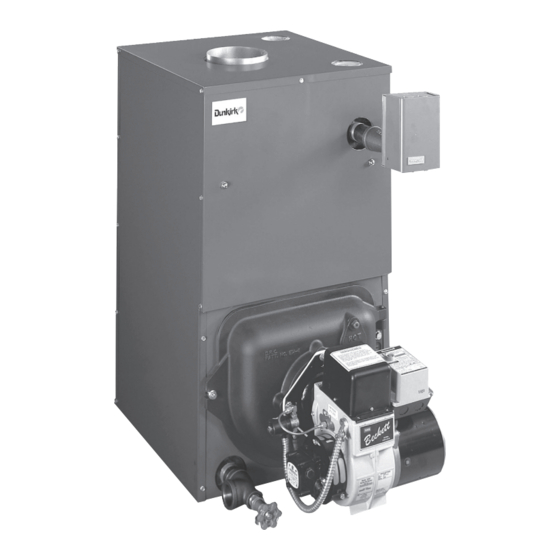
OIL-FIRED CAST IRON
HOT WATER
INSTALLATION, OPERATION
& MAINTENANCE MANUAL
Maximum Allowable
Working Pressure 50 psi.
Manufactured by:
ECR International, Inc.
2201 Dwyer Avenue, Utica NY 13501
web site: www.ecrinternational.com
EMPIRE II
SERIES
P/N# 240009549, Rev. B [10/2012]
II
Advertisement
Table of Contents

Related Manuals for Dunkirk 3EW.65


Summary of Contents for Dunkirk 3EW.65
- Page 1 EMPIRE II SERIES Models OIL-FIRED CAST IRON 3EW.65 HOT WATER 3EW.75 3EW1.00 4EW.90 INSTALLATION, OPERATION 4EW1.25 & MAINTENANCE MANUAL 4EW1.50 5EW1.20 5EW1.75 Maximum Allowable Working Pressure 50 psi. Manufactured by: ECR International, Inc. 2201 Dwyer Avenue, Utica NY 13501 An ISO 9001-2008 Certified Company P/N# 240009549, Rev.
-
Page 2: Table Of Contents
SAFETY NOTICES Introduction Safety Notices ..........2 Empire Water boiler is a natural draft oil fi red hot water Boiler Ratings And Capacities ......3 boiler comprised of cast iron sections. Empire Water boiler is available with 3, 4, or 5 cast iron sections. These Fresh Air For Combustion....... -
Page 3: Boiler Ratings And Capacities
CHIMNEY CAPACITY RATING Without SEC. SIZE/ *Mbh WATER +gph *Mbh Tankless Coil HEIGHT *Mbh »3EW.65 0.65 86.3 8” X 8” X 15” 14½ »3EW.75 0.75 85.2 8” X 8” X 15” 14½ 3EW1.00 1.00 84.0 8” X 8” X 15”... - Page 4 SAFE INSTALLATION AND OPERATION WARNING NOTICE This boiler has been designed for residential Burn and scald hazard. Safety relief valve could installations. If used for commercial applications, discharge steam or hot water during operation. all jurisdictional requirements must be met. This Install discharge piping per these instructions.
- Page 5 LOCATING THE BOILER Complete Prior To Installing Boiler. Place boiler in location centralized with the piping system and as close to chimney as possible. A. Verify you have selected the right size boiler with proper capacity. AHRI rating of boiler selected Boiler must be level.
- Page 6 LOCATING THE BOILER Figure 3 - Boiler With Piping System...
-
Page 7: Fresh Air For Combustion
FRESH AIR FOR COMBUSTION EXAMPLE 2: Boiler Located in Confi ned Space WARNING Asphyxiation, fi re hazard. Do not obstruct air All Air from Inside the Building: Confi ned openings to combustion area. Follow instructions space shall be provided with two permanent openings below, to maintain adequate combustion air. - Page 8 FRESH AIR FOR COMBUSTION All Air from Outdoors: Confi ned space shall 3. When communicating with outdoors through be provided with two permanent openings, one horizontal ducts, each opening shall have commencing within 12 inches of top and commencing minimum free area of one square inch per 2,000 within 12 inches of bottom of enclosure.
-
Page 9: System Piping
SYSTEM PIPING Installation of boiler for new heating system, Verify clean cold water supply is available when Install all of radiation units (panels, radiators, connecting to pressure reducing valve. When water baseboard, or tubing) and supply and return mains supply is from well or pump, a sand strainer should be fi... - Page 10 SYSTEM PIPING Figure 7 - Bypass Piping Arrangement Diagram > LOW DESIGN WATER TEMPERATURE SYSTEMS > LARGE WATER CONTENT SYSTEMS > PIPING ARRANGED FOR “POWER PURGING” AIR OUT OF THE SYSTEM PIPING, REFER TO THIS MANUAL’S SECTION ON “FILLING THE SYSTEM WITH WATER”...
- Page 11 SYSTEM PIPING Figure 8 - System Piping Arrangement Zoning With Zone Valves > CIRCULATOR ON SUPPLY PIPING PUMPS AWAY FROM EXPANSION TANK NOTE: CIRCULATOR CAN ALSO BE INSTALLED ON RETURN PIPING. > PIPING ARRANGED FOR “POWER PURGING” AIR OUT OF SYSTEM PIPING, REFER TO THIS MANUAL’S SECTION ON “FILLING THE SYSTEM WITH WATER”...
- Page 12 SYSTEM PIPING Figure 9 - System Piping Arrangement Zoning With Circulators > CIRCULATOR ON SUPPLY PIPING PUMPS AWAY FROM EXPANSION TANK > PIPING ARRANGED FOR “POWER PURGING” AIR OUT OF SYSTEM PIPING, REFER TO THIS MANUAL’S SECTION ON “FILLING THE SYSTEM WITH WATER” OPTION #1...
- Page 13 SYSTEM PIPING Figure 10 - System Piping Arrangement Alternate Near Boiler Piping > PER THIS MANUAL, USE OPTION #2 IN “FILLING THE SYSTEM WITH WATER” > DIAPHRAGM EXPANSION TANK MOUNTED OFF THE BOILER > THIS PIPING ARRANGEMENT CAN BE USED WITH ZONE VALVES OR ZONE >...
- Page 14 fi gure below. Coil provides instantaneous heating Rate (gph) (gpm)‡ of water for domestic use if proper burner and water supply 3EW.65 0.65 2.90 line controls are used. Tankless coils are meant to provide domestic hot water for intermittent draws, not continuous 3EW.75...
- Page 15 SYSTEM PIPING ARRANGEMENT Antifreeze added to boilers must be nontoxic, and PIPING WATER VOLUMES must be of type specifi cally intended for use in closed hydronic heating systems. Under no circumstances COPPER PIPE STEEL PIPE PIPE SIZE should automotive antifreeze be used. Antifreeze used FACTOR FACTOR in any boiler may reduce capacity by 10% or more and...
-
Page 16: Chimney And Chimney Connections
CHIMNEY AND CHIMNEY CONNECTIONS For oil fi red boilers for connections to vents or chimneys, WARNING vent installations shall be in accordance with applicable Fire Hazard. Maintain minimum vent pipe clearance provisions of INSTALLATION OF OIL BURNING EQUIPMENT, NFPA31 latest revision, and applicable provisions of local of 18”... -
Page 17: Typical Chimney Connection
TYPICAL CHIMNEY CONNECTION Figure 12 - Typical Chimney Connection... -
Page 18: Electrical Connections
ELECTRICAL CONNECTIONS WARNING Electric Power Supply Installation must comply with the latest revision of the Electrical shock hazard. Turn OFF electrical power supply National Electrical Code, any other national, state, or local at service panel before making electrical connections. codes or regulations. Failure to do so could result in death or serious injury. -
Page 19: Filling The Boiler
FILLING THE BOILER How A Hot Water System Operates OPTION #2 Entire heating system (boiler, piping, and radiation units) is fi lled with water. As water in the boiler is heated, it • Close air vents on all radiation units. is circulated from top of boiler through supply main to •... -
Page 20: Operating The Boiler
OPERATING THE BOILER Air Supply For Combustion: Start: Fill entire system with water. Vent all air from • Do not install boiler in rooms with insuffi cient air, unless system following section for Filling The Boiler. corrective steps are taken. •... - Page 21 OPERATING THE BOILER Nozzles And Electrodes Oil Burner Maintenance : Use proper size, spray angle, : For Beckett AFG, Carlin EZ1 and spray pattern nozzle. Refer to recommended nozzle or EZ2, and the Riello 40 F3, F5, or F10 perform following selection charts.
- Page 22 OPERATING THE BOILER Figure 13 -Burner Adjustments and Settings...
-
Page 23: Checking And Adjusting Controls
CHECKING AND ADJUSTING CONTROLS Locate thermostat fi ve feet above the fl oor on inside wall. WARNING Locate thermostat to sense average room temperature, Burn, scald hazard. Do not attempt to start the avoid the following: burner when excess oil has accumulated, when THERMOSTAT LOCATIONS TO AVOID the unit is full of vapor, or when the combustion DEAD... -
Page 24: Maintenance
MAINTENANCE Annually Diaphragm Expansion Tank : Recommend fl ue passages, combustion : Tank may become chamber area (target wall, fi re door insulation, water logged. Frequent automatic opening of safety relief durablanket), burner adjustment, control operation, and valve indicates water logging. High boiler temperature boiler seals (fi... -
Page 25: Oil Boiler Cleaning Instructions
OIL BOILER / BURNER CLEANING INSTRUCTIONS Oil Boiler Cleaning: Carefully vacuum soot accumulations from combustion chamber area, take care to not damage Shut off all electrical power to boiler / burner and shut any of refractory or blanket insulation. To gain off fuel oil supply. -
Page 26: Oil Burner Cleaning
OIL BURNER CLEANING These are general instructions for cleaning an oil burner. For specifi cs, consult burner manufacturer’s instructions. WARNING Electrical shock hazard. Turn OFF electrical power supply at service panel before making electrical connections. Failure to do so could result in death or serious injury. Verify all electrical power to boiler / burner and fuel supply to burner are shut off. -
Page 27: Service Hints
SERVICE HINTS You may avoid inconvenience and service calls by checking these points before you call for service: IF YOUR SYSTEM IS NOT HEATING OR NOT GIVING ENOUGH HEAT . . . POSSIBLE CAUSE WHAT TO DO Thermostat is not set correctly Reset thermostat Check fl... -
Page 28: Electrical Wiring
ELECTRICAL WIRING Figure 16 - Boiler Honeywell L7248L Control... - Page 29 ELECTRICAL WIRING Figure 17 - Honeywell L7248L Control With Reillo F5/F10 Burner...
-
Page 30: Equipment And Optional Accessories
EQUIPMENT AND OPTIONAL ACCESSORIES MAIN AIR VENT: for down fl ow systems or diaphragm CIRCULATOR (provided) Every forced hot water system requires circulator. Separate type expansion tanks (not provided) circulator or zone valve is required for each zone, if there Before system is fi... - Page 31 NOTES...
- Page 32 DUNKIRK BOILERS 2201 Dwyer Avenue, Utica NY 13501 web site: www.ecrinternational.com...
Need help?
Do you have a question about the 3EW.65 and is the answer not in the manual?
Questions and answers