Table of Contents
Advertisement
Table of Contents
1 Summary . . . . . . . . . . . . . . . . . . . . . . . . . . . . . . . . . . . . . . . . . . . . . . . . . . . . . . . . . . . . . . . . . . . . . . . . . . . . . . . . . . . . . . . . . . . . . . 3
1.1 Name plate ........................................................................................................ 3
1.2 Product series .................................................................................................... 4
1.3 Technical standards ............................................................................................ 6
1.4 Peripheral Electrical Devices and System Configuration...................................... 8
1.5 Product outline and installation dimensions......................................................... 9
2 Wirings . . . . . . . . . . . . . . . . . . . . . . . . . . . . . . . . . . . . . . . . . . . . . . . . . . . . . . . . . . . . . . . . . . . . . . . . . . . . . . . . . . . . . . . . . . . . . . . 1 4
2.1 Standard wiring diagrams ................................................................................. 14
2.2 Main circuit wiring terminals ........................................................................... 16
2.3 Control circuit wiring terminals ........................................................................ 17
3 Panel operations . . . . . . . . . . . . . . . . . . . . . . . . . . . . . . . . . . . . . . . . . . . . . . . . . . . . . . . . . . . . . . . . . . . . . . . . . . . . . . . . 2 3
3.1 Keyboard interface ........................................................................................... 23
3.2 Parameter setting example & motor auto-tuning ................................................ 25
3.3 JOG ................................................................................................................. 26
4 Function codes (Parameters) . . . . . . . . . . . . . . . . . . . . . . . . . . . . . . . . . . . . . . . . . . . . . . . . . . . . . . . . . . . . 2 7
4.1 Basic monitoring parameters: d0.00-d0.41 ........................................................ 27
4.2 Basic functions group: P0.00-P0.28 .................................................................. 31
4.3 First motor parameters: P1.00-P1.37 ................................................................. 41
4.4 V/F control parameters: P2.00-P2.15 ................................................................ 46
4.5 Vector control parameters: P3.00-P3.22 ............................................................ 51
4.6 Input terminals: P4.00-P4.39 ............................................................................ 55
4.7 Output terminals: P5.00-P5.22 .......................................................................... 68
4.8 Start/stop control: P6.00-P6.15 ......................................................................... 74
4.9 Operation panel and display: P7.00-P7.14 ......................................................... 79
4.10 Auxiliary functions: P8.00-P8.53 .................................................................... 82
4.11 Fault and protection: P9.00-P9.70 ................................................................... 92
4.12 PID functions: PA.00-PA.28......................................................................... 103
4.13 Swing Frequency, Fixed Length and Count: PB.00-PB.09 ............................. 108
4.14 Multi-reference and simple PLC: PC.00-PC.51 ............................................. 111
4.15 Communication parameters: PD.00-PD.06 .................................................... 116
4.16 PE group: reserved ....................................................................................... 117
4.17 Function code management: PP.00-PP.04 ..................................................... 117
4.18 Torque control parameters: B0.00-B0.08....................................................... 119
4.19 Control optimization parameters: B5.00-B5.09.............................................. 121
4.20 Extended function parameters: B9.00-B9.09 ................................................. 123
Advertisement
Table of Contents

Summary of Contents for Jaden DLB1-0D40S2G
- Page 1 Table of Contents 1 Summary ....................3 1.1 Name plate ......................
-
Page 2: Table Of Contents
5 Fault and solutions ................1 2 4 5.1 Fault and solutions .................. -
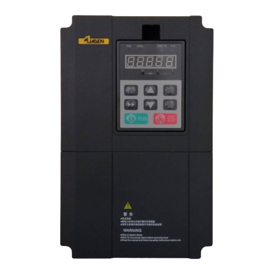
Page 3: Summary
1 Summary 1.1 Name plate Graph 1-1 Nameplate Important: Please read Appendix VI Safety Instructions carefully before and during using JADEN DLB1 inverters. -
Page 4: Product Series
1.2 Product series Rated output Rated input current Rated output Inverter model power(kW) current (A) Single Phase input:AC 220V-15%~+10%, 50/60Hz DLB1-0D40S2G DLB1-0D75S2G 0.75 DLB1-01D5S2G 14.1 DLB1-02D2S2G 24.2 Three phase input:AC 380V-15%~+10%, 50/60Hz DLB1-0D75T4G 0.75 DLB1-01D5T4G DLB1-02D2T4G DLB1-0004T4G 10.5 DLB1-05D5T4G 15.5 DLB1-07D5T4G 20.5... - Page 5 DLB1-0355T4G 754.5 DLB1-0400T4G 797.6 Three phase input: AC 660V-15%~+10%, 50/60Hz 0.75 DLB1-0D75T7G DLB1-01D5T7G DLB1-02D2T7G DLB1-0004T7G DLB1-05D5T7G 12.5 DLB1-07D5T7G 18.3 DLB1-0011T7G 23.1 DLB1-0015T7G 29.8 DLB1-0018T7G 35.7 DLB1-0022T7G 41.7 DLB1-0030T7G 57.4 DLB1-0037T7G 66.5 DLB1-0045T7G 81.7 DLB1-0055T7G 101.9 DLB1-0075T7G 137.4 DLB1-0090T7G 151.8 DLB1-0110T7G 185.3 DLB1-0132T7G 220.7...
-
Page 6: Technical Standards
1.3 Technical standards Specifications Control system CurrentVector General Purpose Inverter. Compatible motor Induction motor and Synchronous motor. Maximum Vector control:0~300Hz; frequency V/F control:0~3200Hz. Wave-carrier 0.5kHz~16kHz; frequency Depending on load, can automatically adjust wave-carrier frequency. Input frequency Digital setting:0.01Hz; resolution Analog setting:maximum frequency×0.025%. Open vector control(SVC);... - Page 7 Power dip ride The load feedback energy compensates the voltage reduction so that the through Invertercan continue to run for a short time. Timing control Time range: 0.0–6500.0 minutes Two-motor Two motors can be switched over via two groups of motor parameters. switchover Fieldbus Supports RS485, Profibus-DP, CANlink, CANopen (need extention cards)
-
Page 8: Peripheral Electrical Devices And System Configuration
1.4 Peripheral Electrical Devices and System Configuration Power Circuit bra ker Contact or Brake AC reactor resistor EMC filter Brake unit Inverter DC react or Grounding AC reacto r EMC filter Motor Groundin g Graph 1-2 Peripheral electrical devices... -
Page 9: Product Outline And Installation Dimensions
1.5 Product outline and installation dimensions 1.5.1 Product outline& installation dimensions Graph 1-3 0.4W~1.5KW product outlines & dimensions Graph 1-42.2KW~3.7KW product outline & dimensions... - Page 10 Graph 1-5 5.5~7.5KW product outline & dimensions Graph 1-611~18.5KW product outline & dimensions -10-...
- Page 11 Graph 1-722~30KW product outline & dimensions Graph 1-837~55KW product outline & dimensions -11-...
- Page 12 Graph 1-875~110KW product outline & dimensions Graph 1-9 132~160KW product outline & dimensions -12-...
- Page 13 1.5.2 Detachable keyboard(operation panel) dimensions Graph 1-10 detachable keyboard outline dimensions Graph 1-11 detachable keyboard aperture dimensions -13-...
-
Page 14: Wiring
2 Wirings 2.1 Standard wiring diagrams Graph 2-8 0.4~18.5KW inverter wiring diagram -14-... - Page 15 Graph 2-922~400KW inverter wiring diagram -15-...
-
Page 16: Main Circuit Wiring Terminals
2.2 Main circuit wiring terminals 0.4KW~15KW: Terminal name Function Three phase power input terminal External brake resistor terminal DC bus negative terminal Three phase AC output terminal Grounding terminal 18.5KW~400KW: POWER MOTOR Terminal name Function R, S, T Three phase power input terminal (+), (-) External brake unit terminal External DC reactor terminal... -
Page 17: Control Circuit Wiring Terminals
2.3 Control circuit wiring terminals 2.3.1 Control circuit terminal definitions +10V +24V +24V 2.3.2 Control circuit signals Category Terminal Name Function Specifications Multi-function Default setting: Forward input terminal operation(FWD) Multi-function Optical coupler Default setting: Forward input terminal insulation JOG(FJOG) DC24V/8mA Multi-function When using external Default setting: Fault reset... - Page 18 Category Terminal Name Function Specifications terminal A node output Default setting: stop fault during B node output operation Node capacity: TA1—TC1: normally open AC250V, 3A. Node output TB1—TC1: normally close common terminal open collector output; Open collector Default setting: inverter in Optical-coupler output operation...
- Page 19 2.3.3Control circuitwiring notes Analog input terminal As analogy voltage signals can be easily affected by external interference, shielded cables shall be used. Cables shall be as short as possible and not exceeding 20 meters. As shown in Graph 2-12 & 2-13, in some severe circumstances, filter capacitor or ferrite bread shall be used in analog signal side.
- Page 20 + 2 4 V + V C C + 2 4 V 信号 D 1 1 4 . 7 K N P N 3 . 3 Ω D 1 5 4 . 7 K C O M E x t e r n a l I n v e r t e r c o n t r o l l e r Graph 2-14 NPN inputwirng...
- Page 21 I n v e r t e r + 2 4 V R e l a y D O 1 M a x c u r r e n t : 5 0 m A D O 2 C M E C O M Graph2-16Digital output wiring -21-...
- Page 22 2.3.4 Control circuit jumper Graph 2-170.4KW~93KW control board jumpers Control circuit jumper 1, SP jumper(J9) 4、AI1 Jumper(J4) E x t e r n a l I n t e r n a l 2 4 V p o w e r 0 - 1 0 V 0 - 2 0 m A 2、...
-
Page 23: Panel Operations 2
3 Panel operations 3.1 Keyboardinterface Keyboard can edit inverter function parameters; monitor inverter work status; and control inverter operationssuch as start/stop. The outline is as below: Panel functions Keyboard/ Descriptions Light Direction ON:FWD status OFF:REV status Operation ON:RUN status OFF: STOP status Command source ON: terminal operation control status LOCAL... - Page 24 Can display setting frequency, output frequency, monitor Digital display data and fault etc. Program key: MON/ESC Enter level 1 menu or escape Shit key: >> Select parameter when at run or stop; When editing parameters, can select place for editing. Confirm key: DATA/ENTER Confirm parameters...
-
Page 25: Parameter Setting Example & Motor Auto-Tuning
3.2 Parameter setting example& motor auto-tuning Functioncode inspect and edit DLB1 inverter panel has a three-level structure:function codegroup(level 1menu)→ function code(level 2 menu)→ function code setting(level 3 menu). Graph 3-2 Example:Change P3.02 from 10.00Hz to15.00Hz, as shown in Graph3-3. Graph 3-3 Parameter inspection Please refer to P7.03, P7.04, P7.05 for parameter inspect settings. - Page 26 Motor parameter auto-tuning Procedures: Set P0.02=0 (operation panel as command source channel) Input motor actual parameters: Motor selection Parameters P1.00:motor type selection P1.01:rated power Motor1 P1.02:rated voltageP1.03:rated current P1.04:rated frequencyP1.05:rated speed If (asynchronous) motor can separate from load, set P1.37=2 (asynchronous motor complete auto-tuning) and press RUN key.
-
Page 27: Function Codes (Parameters) 2
4 Function codes (Parameters) Legends: “★”:this parameter’s setting value is not editable when inverter is at operation status; “● ”:this parameter’s value is observed value, not editable; “☆”:this parameter’s setting value is editable when inverter is at stop or operation status; “▲”:this parameter is “factory parameter”... - Page 28 0~14 input terminal status place invald valid 2 12 2 11 VDI5 VDI4 VDI3 VDI2 VDI1 DI10 d0.08 DO output status It indicates the current state of DO terminals. After the value is converted into a binary number, each bit corresponds to a DO.
- Page 29 d0.12 Counter value PB parameter group counter functionPB.08~PB.09. d0.13 Length value PB parameter group fixed-length functionPB.05~PB.07. d0.14 Load speed display Motor actual running speed. d0.15 PID setting PIDpreset value percentage. d0.16 PID feedback PID feedback value percentage. d0.17 PLC phase PLC phase display.
- Page 30 d0.29 Encoder feedback speed 0.01Hz PG feedback speed, accurate to 0.1Hz. d0.30 Main frequencyX display 0.01Hz P0.03 main frequency source setting value Auxiliary frequencyY display d0.31 0.01Hz P0.04 auxiliary frequency sourcesetting value. d0.32 Inverter status d0.33 Target torque(%) 0.1% Under torque control mode, monitortarget torque. d0.34 Motor temperature value Motor temperature value display.Can also select different temperature measuring point to monitor...
-
Page 31: Basic Functions Group: P0.00-P0.28
4.2 Basic functions group:P0.00-P0.28 Defa Restri Code Description Setting range ctions G type P0.00 Load type ● P type This parameter is used to display the delivered model and cannot be modified. 1: Applicable to constant torque load with rated parameters specified 2: Applicable to variable torque load (fan and pump) with rated parameters specified. - Page 32 Commands are given by means of multi-functional input terminals with functions such as FWD, REV, FJOG, and RJOG. 2: Communication control ("LOCAL" indicator blinking) Commands are given from upper controllers. If this parameter is set to 2, a communication card (Modbus RTU, PROFIBUS-DP card, CANlink card, user programmable card or CANopen card) must be installed.
- Page 33 3: AI2 (0-10 V voltage input or 4-20 mA current input, determined by jumper J8) The frequency is set by analog input. The DLB1 control board provides two analog input (AI) terminals (AI1, AI2). The DLB1 provides three curves indicating the mapping relationship between the input voltage of AI1&...
- Page 34 Keyboard setting frequency(P0.08, UP/DOWN editable, not retentive at power failure) Keyboard setting frequency(P0.08, UP/DOWN editable, retentive at power failure) Analog AI1 setting Analog AI2 setting Auxiliary frequency ★ P0.04 source Y selection AI3(keyboard potentiometer) High speed pulse setting(DI5) Multi-speed operation setting Simple PLC setting PID control setting Remote communication setting...
- Page 35 One’s Frequencysource selection place Main frequency source X X and Y operation (operation relationship determined by Ten’s place) Main frequency source X and Auxiliary frequency source Y switchover Switchover between X and "X and Y Frequency source ☆ P0.07 operation" combination mode Switchover between X and "Y and Y operation"...
- Page 36 • If P0.22is set to 1, the frequency reference resolution is 0.1 Hz. In this case, the setting range of F0-10 is 50.0 to 3200.0 Hz. • If P0.22 is set to 2, the frequency reference resolution is 0.01 Hz. In this case, the setting range of F0-10 is 50.00 to 320.00 Hz.
- Page 37 If the carrier frequency is high, power loss and temperature rise of the motor declines. However, the inverter has an increase in power loss, temperature rise and interference. Adjusting the carrier frequency will exert influences on the aspects listed in the following table. →...
- Page 38 The DLB1 provides totally four groups of acceleration/deceleration time for selection. You can perform switchover by using a DI terminal. • Group 1: P0.17, P0.18 • Group 2: P8.03, P8.04 • Group 3: P8.05, P8.06 • Group 4: P8.07, P8.08 Acceleration/decelera ★...
- Page 39 Maximum frequency(P0.10) Acceleration/Decelera tion time base Set frequency ★ P0.25 frequency 100Hz The acceleration/deceleration time indicates the time for the Inverter to increase from 0 Hz to the frequency set in P0.25. If this parameter is set to 1, the acceleration/deceleration time is related to the set frequency.
- Page 40 Simple PLC Communication setting Hundred’s Binding terminal command to place frequency source No binding Frequency source by digital setting AI3( keyboard potentiometer) Pulse setting(DI5) Multi-reference instruction Simple PLC Communication setting It is used to bind the three running command sources with the nine frequency sources, facilitating to implement synchronous switchover.
-
Page 41: First Motor Parameters: P1.00-P1.37
4.3 First motor parameters:P1.00-P1.37 Defa Restricti Code Description Setting range Common asynchronous motor Variable frequency asynchronous Motor type selection ★ P1.00 motor Permanent magnetic synchronous motor Motorrated power ★ P1.01 0.1kW~1000.0kW Motorrated voltage ★ P1.02 1V~2000V 0.01A~655.35A( inverter rated power 55kW) Motorrated current ★... - Page 42 Synchronous motor stator 0.001 ~65.535 ( inverter power<=55kW) ★ P1.16 resistance 0.0001 ~6.5535 ( inverter power>55kW) 0.01mH~655.35mH( inverter Synchronous motor shaft D power<=55kW) ★ P1.17 inductance 0.001mH~65.535mH( inverter power>55kW) 0.01mH~655.35mH( inverter Synchronous motor shaft Q power<=55kW) ★ P1.18 inductance 0.001mH~65.535mH( inverter power>55kW) Inductance resistance unit ★...
- Page 43 Forward A/B phase sequence of ABZ ★ P1.30 incremental encoder Reverse This parameter is valid only for ABZ incremental encoder (P1.28 = 0) and is used to set the A/BphasesequenceoftheABZincrementalencoder. It is valid for both asynchronous motor and synchronous motor. The A/B phase sequence can be obtained through "Asynchronous motor complete auto-tuning"...
- Page 44 • 0: No auto-tuning: Auto-tuning is prohibited. • 1: Asynchronous motor static auto-tuning It is applicable to scenarios where complete auto-tuning cannot be performed because the asynchronous motor cannot be disconnected from the load. Before performing static auto-tuning, properly set the motor type and motor nameplate parameters of P1.00 to P1.05 first.
- Page 45 Before performing no-load auto-tuning, properly set the motor type, motor nameplate parameters of P1.00 to P1.05, "Encoder type" (P1.28) and "Encoder pulses per revolution" (P1.27) and "Number of pole pairs of resolver" (P1.34) first. The Inverter will obtain motor parameters of P1.16 to P1.20, encoder related parameters of P1.30 to P1.33 and vector control current loop PI parameters of P3.13 to P3.16 by no-load auto-tuning.
-
Page 46: V/F Control Parameters: P2.00-P2.15
4.4 V/F control parameters:P2.00-P2.15 Group P2 is valid only for V/F control. The V/F control mode is applicable to low load applications (fan or pump) or applications where one Inverter operates multiple motors or there is a large difference between the Inverter power and the motor power. - Page 47 In this mode, V and F are proportional and the proportional relationship can be set in P2.13. The relationship between V and F are also related to the rated motor voltage and rated motor frequency in Group F1. Assume that the voltage source input is X (0 to 100%), the relationship between V and F is: V/F = 2 * X * (Rated motor voltage)/(Rated motor frequency) Hundred’s place:automatic voltage regulation (AVR) function CP U automatically optimizes DC bus voltage when grid power supply fluctuates..
- Page 48 V1-V3: 1st, 2nd and 3rd voltage P1.F3: 1st, 2nd and 3rd frequency percentages of multi-point V/F percentages of multi-point V/F Vb: Rated motor voltage Fb: Rated motor running frequency ☆ P2.09 0.0% V/F slip compensation gain 0%~200.0% This parameter is valid only for the asynchronous motor. It can compensate the rotational speed slip of the asynchronous motor when the load of the motor increases, stabilizing the motor speed in case of load change.
- Page 49 Set this parameter to 0 if the motor has no oscillation. Increase the value properly only when the motor has obvious oscillation. The larger the value is, the better the oscillation suppression result will be. When the oscillation suppression function is enabled, the rated motor current and no-load current must be correct.
- Page 50 • 6: Simple PLC If the voltage source is simple PLC mode, parameters in group PC must be set to determine the setting output voltage. • 7: PID The output voltage is generated based on PID closed loop. For details, see the description of PID in group PA.
-
Page 51: Vector Control Parameters: P3.00-P3.22
4.5 Vector control parameters:P3.00-P3.22 P3 group is valid for vector control, and invalid for V/F control. Restri Code Description Setting range Default ctions Speed loop proportional gain ☆ P3.00 1~100 ☆ P3.01 Speed loop integral time 1 0.01s~10.00s 0.50s ☆ P3.02 5.00Hz Switchover frequency 1... - Page 52 aware that this may lead to system oscillation. The recommended adjustment method is as follows: If the factory setting cannot meet the requirements, make proper adjustment. Increase the proportional gain first to ensure that the system does not oscillate, and then reduce the integral time to ensure that the system has quick response and small overshoot.
- Page 53 AI3( keyboard potentiometer) Pulse setting Communication setting Min(AI1, AI2) Max(AI1, AI2) Digital setting of torque upper 0.0%~200.0% ☆ P3.10 150.0% limit in speed control mode In the speed control mode, the maximum output torque of the Inverter is restricted by P3.09. If the torque upper limit is analog, pulse or communication setting, 100% of the setting corresponds to the value of P3.10, and 100% of the value of P3.10 corresponds to the Inverter rated torque.
- Page 54 Field weakening integral ☆ P3.22 2~10 multiple These parameters are used to set field weakening control for the synchronous motor. If P3.18 is set to 0, field weakening control on the synchronous motor is disabled. In this case, the maximum rotational speed is related to the Inverter bus voltage. If the motor's maximum rotational speed cannot meet the requirements, enable the field weakening function to increase the speed.
-
Page 55: Input Terminals: P4.00-P4.39
4.6 Input terminals:P4.00-P4.39 The DLB1 provides six DI terminals (DI5 can be used for high-speed pulse input) and three analog input (AI) terminals. The optional extension card provides another four DI terminals (DI7 to DI10) and an AI terminal (AI3x). Defa Restri Code... - Page 56 The Inverter decelerates to stop, but the running parameters are all memorized, such as PLC, swing frequency and PID RUN pause parameters. After this function is disabled, the Inverter resumes its status before stop. If this terminal becomes ON, the Inverter reports 15=E.EIOF Normally open (NO) and performs the fault protection action.
- Page 57 Length reset This terminal is used to clear the length. Torque control The Inverter is prohibited from torque control and enters the prohibited speed control mode. Pulse input (enabled DI5 is used for pulse input. only for DI5) Reserved Reserved. Immediate DC After this terminal becomes ON, the Inverter directly braking...
- Page 58 When this terminal becomes ON, the Inverter stops within the shortest time. During the stop process, the current Emergency stop remains at the set current upper limit. This function is used to satisfy the requirement of stopping the Inverter in emergency state.
- Page 59 Two terminals for acceleration/deceleration time selection have four state combinations, as listed in the following table. Acceleration/ Terminal Terminal Corresponding deceleration time parameter selection Acceleration/Deceleration P0.17, P0.18 time 1 Acceleration/Deceleration P8.03, P8.04 time 2 Acceleration/Deceleration P8.05, P8.06 time 3 Acceleration/Deceleration P8.07, P8.08 time 4...
- Page 60 It is the most commonly used two-line mode, in which the forward/reverse rotation of the motor is decided by DI1x and DIy. The parameters are set as below: Value Function Description Forward operation(FWD) Reverse operation(REV) As shown in the below figure, when only K1 is ON, the Inverter instructs forward rotation. When only K2 is ON, the Inverter instructs reverse rotation.
- Page 61 2:Three-line mode 1; S B 2 D I x ( F WD ) S B 1 D I n R U N e n a b l e d S B 3 D I y ( R E V ) C OM SB1:Stop button SB2:FWD button...
- Page 62 SB1:Stop button SB2:Run button In this mode, DIn is enable terminal, DIx is RUN terminal and DIy terminal decides operation direction . Value Function Description Direction Enable 0: invalid; 1: valid; X: random. Operation Stop 4 Two-line mode 3; D I x ( F O R ) D I y ( R E V ) C OM In this mode, the earlier valid terminals have priorities.
- Page 63 5:Three-line mode 3; S B 2 D I x ( F WD ) S B 1 D I n R U N e n a b l e d S B 3 D I y ( R E V ) C OM SB1: Stop button SB2: FWD button...
- Page 64 AI curve 1 minimum input ☆ P4.13 0.00V 0.00V~P4.15 Corresponding setting of AI ☆ P4.14 0.0% -100.00%~100.0% curve 1 minimum input AI curve 1 maximum input ☆ P4.15 P4.13~10.00V 10.00V Corresponding setting of AI ☆ P4.16 -100.00%~100.0% 100.0% curve 1 maximum input AI1 filter time ☆...
- Page 65 AI curve 2 minimum input ☆ P4.18 0.00V 0.00V~P4.20 Corresponding setting of AI ☆ P4.19 0.0% -100.00%~100.0% curve 2 minimum input AI curve 2 maximum input ☆ P4.20 P4.18~10.00V 10.00V Corresponding setting of AI ☆ P4.21 -100.00%~100.0% 100.0% curve 2 maximum input AI2 filter time ☆...
- Page 66 The one's place, ten's place and hundred's place of this parameter are respectively used to select the corresponding curve of AI1, AI2 and AI3. Any of the five curves can be selected for AI1, AI2 and AI3. The DLB1 provides two AI terminals as standard. AI3x is provided by an optional extension card. One’s Setting for AI1 less than minimum input place...
- Page 67 High level valid Low level valid DI3 valid mode Hundred’s place High level valid Low level valid DI4 valid mode Thousand's place High level valid Low level valid Ten Thousand's DI5 valid mode place High level valid Low level valid DI6 valid mode One’s place High level valid...
-
Page 68: Output Terminals: P5.00-P5.22
4.7 Output terminals:P5.00-P5.22 The DLB1 provides two analog output (AO) terminals, a digital output (DO) terminal, a relay terminal and a FM terminal (used for high-speed pulse output or open-collector switch signal output) as standard. If these output terminals cannot satisfy requirements, use an optional I/O extension card that provides a relay terminal (relay 2) and a DO terminal (DO2). - Page 69 If the Inverter runs with the output Zero-speed running (no frequency of 0, the terminal becomes ON. If output at stop) the Inverter is in the stop state, the terminal becomes OFF. The Inverter judges whether the motor load exceeds the overload pre-warning threshold before performing the protection Motor overload pre-warning action.
- Page 70 Frequency upper limit If the running frequency reaches the upper reached limit, the terminal becomes ON. If the running frequency reaches the lower Frequency lower limit limit, the terminal becomes ON. In the stop reached (no output at stop) state, the terminal becomes OFF. If the Inverter is in undervoltage state, the Undervoltage state output terminal becomes ON.
- Page 71 If the heatsink temperature of the inverter module (P7.07) reaches the set module Module temperature reached temperature threshold (P8.47), the terminal becomes ON. Software current limit Refer to the descriptions of P8.36 and exceeded P8.37. Frequency lower limit If the running frequency reaches the lower reached (having output at limit, the terminal becomes ON.
- Page 72 Output voltage 0 to 1.2 times of rated Inverter voltage Pulse input 0.01-100.00 kHz 0-10 V 0-10 V (or 0-20 mA) 0-0 V Length 0 to maximum set length Count value 0 to maximum count value Communication setting 0.0%-100.0% 0 to rotational speed corresponding to Motor rotational speed maximum output frequency Output current...
- Page 73 FMR output delay time ☆ P5.17 0.0s 0.0s~3600.0s Relay 1 output delay time ☆ P5.18 0.0s~3600.0s 0.0s Relay 2 output delay time ☆ P5.19 0.0s 0.0s~3600.0s DO1 output delay time ☆ P5.20 0.0s 0.0s~3600.0s DO2 output delay time ☆ P5.21 0.0s 0.0s~3600.0s These parameters are used to set the delay time of output terminals FMR, relay 1, relay 2, DO1...
-
Page 74: Start/Stop Control: P6.00-P6.15
4.8 Start/stop control:P6.00-P6.15 Restri Code Description Setting range ault ctions Direct start Rotational speed tracking restart ☆ P6.00 Start mode Pre-excited start (asynchronous motor) • 0: Direct start -If the DC braking time is set to 0, the Inverter starts to run at the startup frequency. -If the DC braking time is not 0, the Inverter performs DC braking first and then starts to run at the startup frequency. - Page 75 ☆ P6.03 0.00Hz 0.00Hz~10.00Hz Startup frequency Startup frequency holding ★ P6.04 0.0s 0.0s~100.0s time To ensure the motor torque at Inverter startup, set a proper startup frequency. In addition, to build excitation when the motor starts up, the startup frequency must be held for a certain period. The startup frequency (P6.03) is not restricted by the frequency lower limit.
- Page 76 • If the rated motor current is less than or equal to 80% of the rated Inverter current, the base value is the rated motor current. • If the rated motor current is greater than 80% of the rated Inverter current, the base value is 80% of the rated Inverter current.
- Page 77 Output Frequency Frequency Rated Frequenc time t Graph4.12 S-curve acceleration/deceleration B Decelerate to stop ☆ P6.10 Stop mode Coast to stop 0: Decelerate to stop After the stop command is enabled, the Inverter decreases the output frequency according to the deceleration time and stops when the frequency decreases to zero.
- Page 78 This parameter specifies the holding time of DC braking. If it is set to 0, DC braking is cancelled. The stop DC braking process is shown in the following figure. ☆ P6.15 100% 0%~100% Brake use ratio It is valid only for the Inverter with internal braking unit and used to adjust the duty ratio of the braking unit.
-
Page 79: Operation Panel And Display: P7.00-P7.14
4.9 Operation panel and display:P7.00-P7.14 Restri Code Description Setting range ault ctions DIR/JOG disabled Switchover between operation panel control and remote command control (terminal or communication) ★ P7.01 DIR/JOG function Switchover between forward rotation and reverse rotation Forward JOG Reverse JOG DIR/JOG key is a multifunctional key. - Page 80 D0 status Running 1(Hz) frequency AI1 Voltage (V) (Hz) frequency AI2 Voltage (V) DC bus Voltage AI3 Voltage(V) Output voltage Counter value Output current (kW) Length Output power Output Load speed Torque PID setting DI status If a parameter needs to be displayed during the running, set the corresponding bit to 1, and set P7.03 to the hexadecimal equivalent of this binary number.
- Page 81 1.000 Load speed display ☆ P7.06 0.0001~6.5000 coefficient This parameter is used to adjust the relationship between the output frequency of the Inverter and the load speed. For details, see the description of P7.12. Heatsink temperature of P7.07 ● 0.0 ~100.0 inverter module It is used to display the insulated gate bipolar transistor (IGBT) temperature of the inverter module, and the IGBT overheat protection value of the inverter module depends on the model.
-
Page 82: Auxiliary Functions: P8.00-P8.53
4.10 Auxiliary functions:P8.00-P8.53 Restri Code Description Setting range Default ctions JOG running frequency ☆ P8.00 2.00Hz 0.00Hz~ maximum frequency JOG acceleration time ☆ P8.01 20.0s 0.0s~6500.0s JOG deceleration time ☆ P8.02 20.0s 0.0s~6500.0s These parameters are used to define the set frequency and acceleration/deceleration time of the Inverter when jogging. - Page 83 Forward/Reverse rotation ☆ P8.12 0.0s 0.00s~3000.0s dead-zone time It is used to set the time when the output is 0 Hz at transition of the Inverter forward rotation and reverse rotation, as shown in the following figure. Output Frequency Hz time t dead-zone time Enabled...
- Page 84 It is used to set the Inverter running mode when the set frequency is lower than the frequency lower limit. The DLB1 provides three running modes to satisfy requirements of various applications. ☆ P8.15 0.00Hz Droop control 0.00Hz~10.00Hz This function is used for balancing the workload allocation when multiple motors are used to drive the same load.
- Page 85 Frequency detection value ☆ P8.19 50.00Hz 0.00Hz~ maximum frequency (FDT1) Frequency detection hysteresis ☆ P8.20 5.0% 0.0%~100.0%(FDT1 电平) (FDT hysteresis 1) If the running frequency is higher than the value of P8.19, the corresponding DO terminal becomes ON. If the running frequency is lower than value of P8.19, the DO terminal goes OFF These two parameters are respectively used to set the detection value of output frequency and hysteresis value upon cancellation of the output.
- Page 86 Disabled Jump frequency during ☆ P8.22 acceleration/deceleration Enabled It is used to set whether the jump frequencies are valid during acceleration/deceleration. When the jump frequencies are valid during acceleration/deceleration, and the running frequency is within the frequency jump range, the actual running frequency will jump over the set frequency jump amplitude (rise directly from the lowest jump frequency to the highest jump frequency).
- Page 87 Frequency switchover point ☆ P8.25 between acceleration time 1 0.00Hz 0.00Hz~ maximum frequency and acceleration time 2 Frequency switchover point between deceleration time 1 ☆ P8.26 0.00Hz 0.00Hz~ maximum frequency and deceleration time 2 This function is valid when motor 1 is selected and acceleration/deceleration time switchover is not performed by means of DI terminal.
- Page 88 Disabled ☆ P8.27 Terminal JOG preferred Enabled It is used to set whether terminal JOG is preferred. If terminal JOG is preferred, the Inverter switches to terminal JOG running state when there is a terminal JOG command during the running process of the Inverter. Frequency detection value ☆...
- Page 89 Output current P8.34 Zero current detection signal P8.35 0.0%(No detection ) Output over-current ☆ P8.36 200.0% threshold 0.1%~300.0%( motorrated current) Output over-current ☆ P8.37 0.00s 0.00s~600.00s detection delay time Output current P8.36 Output over-current signal P8.37 If the output current of the Inverter is equal to or higher than the overcurrent threshold and the duration exceeds the detection delay time, the corresponding DO becomes ON.
- Page 90 Any current reaching 1 ☆ P8.38 100.0% 0.0%~300.0%( motorrated current) Any current reaching ☆ P8.39 0.0% 0.0%~300.0%( motorrated current) amplitude 1 Any current reaching 2 P8.40 100.0% ☆ 0.0%~300.0%( motorrated current) Any current reaching ☆ P8.41 0.0% 0.0%~300.0%( motorrated current) amplitude 2 If the output current of the Inverter is within the positive and negative amplitudes of any current reaching detection value, the corresponding DO becomes ON.
- Page 91 Module temperature ☆ P8.47 0.00 ~100 threshold When the heatsink temperature of the Inverter reaches the value of this parameter, the corresponding DO becomes ON, indicating that the module temperature reaches the threshold. Fan working during running ☆ P8.48 Cooling fan control Fan working continously It is used to set the working mode of the cooling fan.
-
Page 92: Fault And Protection: P9.00-P9.70
4.11 Fault and protection:P9.00-P9.70 Rest Code Description Setting range Default ricti Disabled Motor overload protection ☆ P9.00 selection Enabled Motor overload protection ☆ P9.01 1.00 0.20~10.00 gain • P9.00 = 0 The motor overload protective function is disabled. The motor is exposed to potential damage due to overheating. - Page 93 In the prerequisite of no overvoltage occurrence, set P9.03 to a small value. For small-inertia load, the value should be small. Otherwise, the system dynamic response will be slow. For large-inertia load, the value should be large. Otherwise, the suppression result will be poor and an overvoltage fault may occur.
- Page 94 Disabled Output phase loss ☆ P9.13 protection selection Enabled It is used to determine whether to perform output phase loss protection. 1st fault type P9.14 ● 0~51 2nd fault type P9.15 0~51 ● 3rd (latest) fault type P9.16 0~51 ● It is used to record the types of the most recent three faults of the Inverter.
- Page 95 28=E.USt2 User defined fault2 29=E.APA Power-on timereached 30=E.ULF Load becoming 0 fault 31=E.PID PID feedback lost duringrunning 40=E.CbC IGBT current limiting fault 41=E.tSr Running motor switchover fault 42=E.SdL Speed deviation too large 43=E.oSF Motor over speed 45=E.oHt Motor over heat 51=E.PoSF Initial position fault It displays the frequency when the latest fault...
- Page 96 It displays the current when the latest fault Current upon 2nd fault P9.28 ● occurs. It displays the bus voltage when the latest Bus voltage upon 2nd fault P9.29 ● fault occurs. It displays the status of all DI terminals whenthe latest fault occurs.
- Page 97 It displays the status of all output terminalswhen the latest fault occurs. The sequence is as follows: BIT4 BIT3 BIT2 BIT1 BIT0 REL2 REL1 Output terminal status upon P9.41 ● 1st fault If an output terminal is ON, the setting is 1. If the output terminal is OFF, the setting is 0.
- Page 98 One’s ☆ Encoder fault (20=E.PG1) place Coast to stop Switch to V/F mode and stop according to stop mode Switch to V/F mode and continue to run Ten’s EEPROM fault (21=E.EEP) place Coast to stop Stop according to stop mode Hundr ed’s reserved...
- Page 99 Coast to stop Stop according to stop mode Continue to run Thous and's Load becoming 0 (30= E. ULF) place Coast to stop Stop according to stop mode Continue to run at 7% of rated motor frequencyand resume to the set frequency if the loadrecovers thous PID feedback lost duringrunning...
- Page 100 If "Continue to run" is selected, the Inverter continues to run and displays A.****. Therunning frequency is set in P9.54. Current running frequency Set frequency Frequency selection for Frequency upper limit P9.54 ☆ continuing to run upon fault Frequency lower limit Backup frequency upon abnormality 100.0 Backup frequency upon...
- Page 101 • If P9.59 = 1, upon instantaneous power failure or sudden voltage dip, the Inverter decelerates. Once the bus voltage resumes to normal, the Inverter accelerates to the set frequency. If the bus voltage remains normal for the time exceeding the value set in P9.61, it is considered that the bus voltage resumes to normal.
- Page 102 normal. ☆ P9.67 20.0% Over-speed detection value 0.0%~50.0%( maximum frequency) ☆ P9.68 1.0s 0.0s~60.0s Over-speed detection time This function is valid only when the Inverter runs in the FVC mode. If the actual motor rotational speed detected by the Inverter exceeds the maximum frequency and the excessive value is greater than the value of P9.67 and the lasting time exceeds the value of P9.68, the Inverter reports 43=E.oSF and acts according to the selected fault protection action.
-
Page 103: Pid Functions: Pa.00-Pa.28
4.12 PID functions:PA.00-PA.28 PID control is a general process control method. By performing proportional, integral and differential operations on the difference between the feedback signal and the target signal, it adjusts the output frequency and constitutes a feedback system to stabilize the controlled counter around the target value. It is applied to process control such as flow control, pressure control and temperature control. - Page 104 MIN(|AI1|, |AI2|) This parameter is used to select the feedback signal channel of process PID. The PID feedback is a relative value and ranges from 0.0% to 100.0%. Forward action ☆ PA.03 PID action direction Reverse action • 0: Forward action When the feedback value is smaller than the PID setting, the Inverter's output frequency rises.
- Page 105 ☆ PA.09 0.0% PID deviation limit 0.0%~100.0% If the deviation between PID feedback and PID setting is smaller than the value of PA.09, PID control stops. The small deviation between PID feedback and PID setting will make the output frequency stabilize, effective for some closed-loop control applications. ☆...
- Page 106 Parameters PA.05、PA.06、PA.07 PA.15 、 PA.16 、 PA.17 PA.20 PA.19 PID deviation In some applications, PID parameters switchover is required when one group of PID parameters cannot satisfy the requirement of the whole running process. These parameters are used for switchover between two groups of PID parameters. Regulator parameters PA.15 to PA.17 are set in the same way as PA.05 to PA.07.
- Page 107 Maximum deviation between ☆ PA.24 1.00% 0.00%~100.00% two PID outputs in reverse direction PA.23 and PA.24 respectively correspond to the maximum absolute value of the output deviation in forward direction and in reverse direction. One’s Integral separated place Invalid Valid ☆...
- Page 108 4.13 Swing Frequency, Fixed Length and Count PB.00-PB.09 The swing frequency function is applied to the textile and chemical fiber fields and the applications where traversing and winding functions are required. The swing frequency function indicates that the output frequency of the Inverter swings up and down with the set frequency as the center.
- Page 109 • If relative to the maximum frequency (PB.00 = 1), the jump frequency is a fixed value. The swing frequency is limited by the frequency upper limit and frequency lower limit. ☆ PB.03 10.0s Swing frequency cycle 0.0s~3000.0s Triangular wave rising time ☆...
- Page 110 allocated with function 9 (Designated count value reached) becomes ON. Then the counter continues to count until the set count value is reached. PB.09 should be equal to or smaller than PB.08. -110-...
-
Page 111: Multi-Reference And Simple Plc: Pc.00-Pc.51
4.14 Multi-reference and simple PLC:PC.00-PC.51 The DLB1 multi-reference has many functions. Besides multi-speed, it can be used as the setting source of the V/F separated voltage source and setting source of process PID. In addition, the multi-reference is relative value. Restric Code Description... - Page 112 PC.19 running PC.21 direction PC.14 PC.02 PC.15 PC.00 time t PC.01 PC.20 PC.18 PC.23 DO or RELAY Output 250ms pulse • 0: Stop after the Inverter runs one cycle The Inverter stops after running one cycle, and will not start up until receiving another command. •...
- Page 113 and running frequency before power failure and will continue to run from the memorized moment after it is powered on again. If the unit's digit is set to 0, the Inverter restarts the PLC process after it is powered on again. PLC retentive upon stop indicates that the Inverter records the PLC running moment and running frequency upon stop and will continue to run from the recorded moment after it starts up again.
- Page 114 Running time of simple PLC ☆ PC.32 0.0s(h) ~6553.5s(h) 0.0s(h) reference 7 Acceleration/deceleration ☆ PC.33 time of simple PLC reference 7 Running time of simple PLC ☆ PC.34 0.0s(h) ~6553.5s(h) 0.0s(h) reference 8 Acceleration/deceleration ☆ PC.35 time of simple PLC reference 8 Running time of simple PLC ☆...
- Page 115 Running time of simple PLC ☆ PC.48 0.0s(h)~6553.5s(h) 0.0s(h) reference 15 Acceleration/deceleration ☆ PC.49 time of simple PLC reference 15 s(s) Time unit of simple PLC ☆ PC.50 h(hour) running PC.00 setting AI3( keyboard potentiometer) ☆ PC.51 Reference 0 source Pulse setting Set by preset frequency (P0.08), modified via terminal UP/DOWN...
-
Page 116: Communication Parameters: Pd.00-Pd.06
4.15 Communication parameters:PD.00-PD.06 Please refer toDLB1 communication protocol Restric Code Description Setting range Default tions One’s place MODBUS 300BPS 600BPS 1200BPS 2400BPS 4800BPS 6005 9600BPS 19200BPS 38400BPS 57600BPS 115200BPS Ten’s place Profibus-DP 115200BPS ☆ PD.00 Bit rate 208300BPS 256000BPS 512000BPS Hundred’s Reserved place... -
Page 117: Pe Group: Reserved
☆ PD.02 1-247, 0 is master station address This device address ☆ PD.03 0ms-20ms Response delay Communication ☆ PD.04 0.0(invlaid), 0.1s-60.0s over-time One’s place MODBUS Non-standard MODBUS protocol Standard MODBUS protocol Ten’s place Profibus-DP ☆ PD.05 Data transfer format PPO1 format PPO2format PPO3format PPO5format... - Page 118 Use control board memory to restore parameters Use keyboard memory 1 to restore parameters Use keyboard memory 2 to restore parameters • 1: Restore default settings except motor parameters If PP.01 is set to 1, most function codes are restored to the default settings except motor parameters, frequency reference resolution (P0.22), fault records, accumulative running time (P7.09), accumulative power-on time (P7.13) and accumulative power consumption (P7.14).
-
Page 119: Torque Control Parameters: B0.00-B0.08
4.18 Torque control parameters:B0.00-B0.08 Restric Code Description Setting range Default tions Speed control Speed/Torque control ★ B0.00 selection Torque control It is used to select the Inverter's control mode: speed control or torque control. The DLB1 provides DI terminals with two torque related functions, function 29 (Torque control prohibited) and function 46 (Speed control/Torque control switchover). - Page 120 Acceleration time in torque ☆ B0.07 0.00s 0.00s~65000s control Deceleration time in torque ☆ B0.08 0.00s 0.00s~65000s control In torque control, the difference between the motor output torque and the load torque determines the speed change rate of the motor and load. The motor rotational speed may change quickly and this will result in noise or too large mechanical stress.
-
Page 121: Control Optimization Parameters: B5.00-B5.09
4.19 Control optimization parameters:B5.00-B5.09 Restric Code Description Setting range Default tions DPWM switchover B5.00 12.00Hz ☆ 0.00Hz~15.00Hz frequency upper limit This parameter is valid only for V/F control. It is used to determine the wave modulation mode in V/F control of asynchronous motor. If the frequency is lower than the value of this parameter, the waveform is 7-segment continuous modulation. - Page 122 guaranteeing uninterrupted running of the Inverter. However, long-time rapid current limit may cause the Inverter to overheat, which is not allowed. In this case, the Inverter will report 40=E.CbC, indicating the Inverter is overloaded and needs to stop. Current detection ☆...
-
Page 123: Extended Function Parameters: B9.00-B9.09
B9.00 Load type ● Pump jack Splicer Extruder Pulling machine After selection corresponding load type, the inverter will configure parameters automatically. For details please contact JADEN directly. ☆ B9.01 User-defined parameter 0 0 ~ 65535 0 ~ 65535 ☆ B9.02 User-defined parameter 1 0 ~... -
Page 124: Fault And Solutions
D L B 1 U s e r Ma n u a l Fault and solutions 5 Fault and solutions 5.1 Fault and solutions T h e D L B 1 p r o v i d e s a t o t a l o f 5 1 p i e c e s o f f a u l t i n f o r ma t i o n a n d p r o t e c t i v e f u n c t i o n s . A f t e r a f a u l t o c c u r s , t h e I n v e r t e r i mp l e me n t s t h e p r o t e c t i o n f u n c t i o n , a n d d i s p l a y s t h e f a u l t c o d e o n t h e o p e r a t i o n p a n e l ( i f t h e o p e r a t i o n p a n e l i s a v a i l a b l e ) . - Page 125 F a u l t N a me D i s p l a y P o s s i b l e C a u s e s S o l u t i o n s 1 : T h e o u t p u t c i r c u i t i s g r o u n d e d o r s h o r t c i r c u i t e d .
- Page 126 F a u l t N a me D i s p l a y P o s s i b l e C a u s e s S o l u t i o n s 1 : E l i mi n a t e e x t e r n a l f a u l t s . 2 : P e r f o r m t h e mo t o r a u t o t u n i n g .
- Page 127 F a u l t N a me D i s p l a y P o s s i b l e C a u s e s S o l u t i o n s 1 : F 9 - 0 1 i s s e t i mp r o p e r l y . 1 : S e t F 9 - 0 1 c o r r e c t l y .
- Page 128 F a u l t N a me D i s p l a y P o s s i b l e C a u s e s S o l u t i o n s 1 : R e p l a c e t h e f a u l t y H A L L 1 : T h e H A L L d e v i c e i s f a u l t y .
- Page 129 F a u l t N a me D i s p l a y P o s s i b l e C a u s e s S o l u t i o n s 1 : R e d u c e t h e l o a d a n d c h e c k 1 : T h e l o a d i s t o o h e a v y o r l o c k e d - t h e mo t o r a n d me c h a n i c a l P u l s e - b y - p u l s e...
-
Page 130: Common Fault And Solutions
5.2 Common fault and solutions You may come across the following faults during the use of the Inverter. Refer to the following table for simple fault analysis. F a u l t P o s s i b l e C a u s e s S o l u t i o n s 1 : T h e r e i s n o p o w e r s u p p l y t o t h e I n v e r t e r o r t h e p o w e r i n p u t t o t h e... - Page 131 F a u l t P o s s i b l e C a u s e s S o l u t i o n s 1 : C h e c k t h e mo t o r a n d t h e mo t o r 1 : E n s u r e t h e c a b l e b e t w e e n t h e c a b l e s .
-
Page 132: Routine Maintenance
6 Repair and maintenance 6.1 Routine maintenance The influence of the ambient temperature, humidity, dust and vibration will cause the aging of the devices in the Inverter, which may cause potential faults or reduce the service life of the Inverter. Therefore, it is necessary to carry out routine and periodic maintenance. Routine maintenance involves checking: Item Details... -
Page 133: Communication Protocol
7 MODBUS communication protocol 7.1 Communication protocol 7.1.1 Protocol content The serial communication protocol defines the information content and the use of serial communication transmissionformat, including: Host polling (or broadcast) format; host encoding method, including: action-requiring function code, data transfer & error correction;... - Page 134 received, each device decodes to determine whether it is sending to themselves. After the last transmitted characters, a pause of at least 3.5-character time marks ending the message. A new message can start after this pause. Whole message must be transmitted as a continuous stream. If there is apause time over 1.5 a character before completion, receiver will refresh and assumes that next byte is address domain of a new message.
- Page 135 Byte number high place Byte number low place F002H high place F002H low place F003H high place F003H high place CRC CHK low place CRC CHK value CRC CHK high place Command code:06H write one word For example:write 5000(1388H) toF00AH of slave address02H. Master command information Information address high place Informationaddress low place...
-
Page 136: Verification Mode
7.2 Verification mode CRC mode:CRC (Cyclical Redundancy Check) uses RTU frame format message, includes error detection method based on CRC fields. CRC field detects the entire contents of the message. CRC field includes two bytes, and contains a 16-bit binary value. It adds to the message after calculations from the transmission equipment. -
Page 137: Communication Addresses
7.3 Communicationaddresses Function codeaddress rules (EEPROM): High place bytes: 00~0F (P0~PF, change P to 0), 40~4F (B0~BF, change B to 4)), 70~7F (D0~DF). Low place byte: 00~FF. For example: P3.12, the address is expressed as F30C. Note: PF group: not readable or editable; Group d: read-only and cannot be changed. - Page 138 Accumulative power-on time 101A Accumulative running time 101B 101C Input pulse frequency, unit1Hz Communication setting value 101D Encoder feedback speed 101E Main frequency X 101F Auxiliary frequency Y 1020 Note: Communication setting value is relevant percentage value, 10000 corresponding to 100.00%, -10000 corresponding-100.00%.
- Page 139 BIT2:RELAY1 output control BIT3:RELAY2 output control BIT4:FMR output control BIT5:VDO1 BIT6:VDO2 BIT7:VDO3 BIT8:VDO4 BIT9:VDO5 Analog output AO1 control:(write only) Command address Command content 2002 0~7FFF for 0%~100% Analog output AO2 control:(write only) Command address Command content 2003 0~7FFF for 0%~100% Pulse output control:(write only) Command address Command content...
- Page 140 0013:Motor auto-tuning fault 0014:Encoder/PG card fault 0015:EEPROM read-write fault 0016:Inverter hardware fault 0017:Motor short circuit to ground 0018:reserved 0019:reserved 001A:Accumulative running timereached 001B:User defined fault 1 001C:User defined fault 2 001D:Accumulative power-on timereached 001E:Load becomes 0 001F:PID feedback lost during running 0028:Pulse-by-pulsecurrent limit fault 0029:Motor switchover fault during running 002A:Speed deviation too large...
- Page 141 Appendix I:Parameterlist Factory Setting Setting Parameter Description setting value1 value 2 Monitoring function group :d0.00-d0.41 d0.00 Running frequency (Hz) 0.01Hz d0.01 Set frequency (Hz) 0.01Hz d0.02 Bus voltage 0.1V d0.03 Output voltage d0.04 Output current 0.01A d0.05 Output power 0.1kW d0.06 Output torque 0.1%...
- Page 142 d0.31 Auxiliary frequency Y 0.01Hz d0.32 Inverter status d0.33 0.1% Target torque(%) d0.34 Motor temperature d0.35 Synchronous motor rotor position 0.0° d0.36 Resolver position d0.37 Z signal counter d0.38 ABZ position Target voltage upon V/F separation d0.39 Output voltage upon V/F separation d0.40 Reserved d0.41...
- Page 143 P0.25 Acceleration/Deceleration time base frequency Base frequency for UP/DOWN modification P0.26 during running P0.27 Binding command source to frequency source P0.28 Communication card type First motor parameters : P1.00-P1.37 P1.00 Motor type selection P1.01 Motorrated power P1.02 Motor rated voltage P1.03 Motor rated current P1.04...
- Page 144 0.00Hz P2.03 Multi-point V/F frequency 1 (F1) Multi-point V/F voltage 1 (V1) 0.0% P2.04 0.00Hz P2.05 Multi-point V/F frequency 2 (F2) P2.06 Multi-point V/F voltage 2 (V2) 0.0% 0.00Hz P2.07 Multi-point V/F frequency 3 (F3) P2.08 Multi-point V/F voltage 3 (V3) 0.0% 0.0% P2.09...
- Page 145 P3.22 Field weakening integral multiple Input terminals:P4.00-P4.39 P4.00 DI1 function selection P4.01 DI2 function selection P4.02 DI3 function selection DI4 function selection P4.03 DI5 function selection P4.04 DI6 function selection P4.05 P4.06 DI7 function selection P4.07 DI8 function selection P4.08 DI9 function selection P4.09 DI10 function selection...
- Page 146 Corresponding setting of pulse maximum input 100.0% P4.31 Pulse filter time 0.10s P4.32 P4.33 AI curve selection P4.34 Setting for AI less than minimum input 0.0s P4.35 DI1 delay time 0.0s P4.36 DI2 delay time 0.0s DI3 delay time P4.37 00000 P4.38 DI valid mode selection 1...
- Page 147 0.00Hz P6.03 Startup frequency 0.0s P6.04 Startup frequency holding time Startup DC braking current/Pre-excited current P6.05 Startup DC braking time/Pre-excited time 0.0s P6.06 P6.07 Acceleration/deceleration mode 30.0% P6.08 Time proportion of S-curve start segment 30.0% P6.09 Time proportion of S-curve end segment P6.10 Stop mode Initial frequency of stop DC braking...
- Page 148 Deceleration time 3 10.0s P8.06 Acceleration time 4 10.0s P8.07 Deceleration time 4 10.0s P8.08 Jump frequency 1 0.00Hz P8.09 Jump frequency 2 0.00Hz P8.10 Frequency jump amplitude 0.00Hz P8.11 0.0s Forward/Reverse rotation dead-zone time P8.12 P8.13 Reverse control Running mode when set frequency lower than P8.14 frequency lower limit 0.00Hz...
- Page 149 Timing function P8.42 Timing duration source P8.43 0.0Min P8.44 Timing duration AI1 input voltage lower limit 3.10V P8.45 AI1 input voltage upper limit 6.80V P8.46 P8.47 Module temperature threshold P8.48 Cooling fan control Wakeup frequency 0.00Hz P8.49 Wakeup delay time 0.0s P8.50 Dormant frequency...
- Page 150 Power-on time upon 3rd fault P9.23 Running time upon 3rd fault P9.24 Frequency upon 2nd fault P9.27 Current upon 2nd fault P9.28 Bus voltage upon 2nd fault P9.29 DI status upon 2nd fault P9.30 Output terminal status upon 2nd fault P9.31 2nd faultinverter status P9.32...
- Page 151 P9.64 10.0% Detection level of load becoming 0 P9.65 Detection time of load becoming 0 1.0s P9.67 20.0% Over-speed detection value P9.68 1.0s Over-speed detection time P9.69 20.0% Detection value of too large speed deviation 5.0s P9.70 Detection time of too large speed deviation PID functions:PA.00-PA.28 PA.00 PID setting source...
- Page 152 Maximum deviation between two PID outputs in 1.00% PA.24 reverse direction PA.25 PID integral property 0.0% PA.26 Detection value of PID feedback loss PA.27 Detection time of PID feedback loss PA.28 PID operation at stop Swing frequency, fixed length and count:PB.00-PB.09 PB.00 Swing frequency setting mode 0.0%...
- Page 153 0.0% PC.14 Multi-reference 14 Multi-reference 15 0.0% PC.15 PC.16 Simple PLC running mode Simple PLC retentive selection upon power PC.17 failure 0.0s(h) PC.18 Running time of simple PLC reference 0 Acceleration/deceleration time of simple PLC PC.19 reference 0 0.0s(h) PC.20 Running time of simple PLC reference 1 Acceleration/deceleration time of simple PLC PC.21...
- Page 154 0.0s(h) PC.38 Running time of simple PLC reference 10 Acceleration/deceleration time of simple PLC PC.39 reference 10 0.0s(h) PC.40 Running time of simple PLC reference 11 Acceleration/deceleration time of simple PLC PC.41 reference 11 0.0s(h) PC.42 Running time of simple PLC reference 12 Acceleration/deceleration time of simple PLC PC.43 reference 12...
- Page 155 PP.04 Parameter modification property Torque control parameters: B0.00-B0.08 B0.00 Speed/Torque control selection B0.01 Torque setting source in torque control 150% B0.03 Torque digital setting in torque control 50.00Hz B0.05 Forward maximum frequency in torque control 50.00Hz B0.06 Reverse maximum frequency in torque control 0.00s B0.07 Acceleration time in torque control...
-
Page 156: Appendix Ii-1Multi-Function Card Dlb1-Pc1
Appendix II:Expansion cards Appendix II-1 Multi-function card DLB1-PC1 1Introduction DLB1-PC1 card provides the following functions : Item Specification Description Input terminal 2 DI DI7~DI8 1 relay output TA2, TB2, TC2 Output terminal 1 DO RS-485 communication Supports Modbus-RTU communication protocol Communication CAN communication Supports CANlink communication protocol... -
Page 157: Terminal Functions
3 Terminal functions Type Terminal Name Function +24V-COM +24V power output Maximum outputcurrent:200mA. Default SP1connects to+24V by jumperJ1. Power Digital input power If use external power supply, user must terminal connect SP1 to external power supply and remove jumper J1. 1, Optical-coupler isolation, compatible with DI7-SP1 Digital input7... -
Page 158: Appendix Ii-2 Encoder Card (Pg Card)
Appendix II-2Encoder card (PG card) 1 Introduction DLB1 supports different kinds of encoder cards(PG card) as optional parts for closed-loop vector controls. PG card models are as below: Name Description Others ABZUVW incremental encoder: Defferential inputPG card, not with frequency demultiplication output;... - Page 159 -159-...
- Page 160 3 Terminal functions ABZUVW differential PGcard DLB1-PG1 specifications DB15 base User terminal Pulling & pluging >22AWG Cable requirement 500kHz Maximum speed ≤7V Input differential signal range DLB1-PG1 terminals Serial number Mark Description Encoder outputA signal positive Encoder output A signal negative Encoder output B signal positive Encoder output B signal negative Encoder output Z signal positive...
- Page 161 Resolver PG card (DLB1-PG2) DLB1-PG2 Specifications DB7 terminal User terminal Pulling & pluging >22AWG Cable requirement 12 bit Resolution 10kHz Excitation frequency VRMS VP-P 3.15±27% DLB1-PG2 terminals Serial number Mark Description PEXC1 Resolver excitation negative PEXC Resolver excitation positive PSINLO Resolver feedbackSIN negative PSIN Resolver feedbackSIN positive...
- Page 162 Appendix IIIBrake accessories The motor and load's regenerative energy is almost completely consumed on the braking resistor when braking. In theory, the power of the braking resistor is consistent with the braking power. But in consideration that the de-rating is 70%, you can calculate the power of the braking resistor according to the formula 0.7 x Pr = Pb x D.
- Page 163 11G/11P 50 /1040W 15G/18.5P 40 /1560W 18.5G/22P 32 /4800W 22G/30P 20 /6000W 30G/37P 20 /6000W 1*2(in External 37G/45P 32 /4800W parallel) 1*2(in 45G/55P 32 /4800W parallel) 1*2(in 55G/75P 20 /6000W parallel) 1*2(in External 75G/93P 18 /9600W parallel) 1*2(in 18 /9600W parallel)...
- Page 164 Appendix IV: Selection of Peripheral Electrical Devices Selecting Peripheral Electrical Devices for DLB1 inverters Input voltage: 380V C a b l e o f C a b l e C a b l e o f O u t p u t I n p u t S i d e C o n t a c t I n v e r t e r Mo d e l...
- Page 165 DLB1-0280T4G/DLB1-315T4P 1000 1000 3×185 2×150 DLB1-0315T4G/DLB1-355T4P 1000 1000 3×185 3×150 DLB1-0355T4G/DLB1-400T4P 1200 1200 4×185 3×185 DLB1-0400T4G 1380 1380 4×185 3×185 Input voltage: 660V C a b l e o f C a b l e o f I n p u t O u t p u t C a b l e o f S i d e...
- Page 166 Selection of external AC & DC reactor Input voltage:380V Input AC reactor output AC reactor DC reactor Induc Inducta Inducta Curre tance Inverter model Current Current (mH (mH) (mH) ) DLB1-0D40T4G/DLB1-0D75T4P DLB1-0D75T4G/DLB1-01D1T4P DLB1-01D1T4G/ DLB1-01D5T4P 0.69 DLB1-01D5T4G/ DLB1-02D2T4P 0.69 DLB1-02D2T4G/ DLB1-03D7T4P 0.69 DLB1-03D7T4G/ DLB1-05D5T4P 0.93...
- Page 167 input AC reactor output AC reactor DC reactor Inducta Inducta Induct Curre Current Current ance Inverter model (mH) (mH) (mH) 20.6 1.83 20.2 0.94 25.3 DLB1-18D5T7G/ DLB1-0022T7P 24.5 1.54 0.79 DLB1-0022T7G/ DLB1-0030T7P 33.5 1.13 32.8 0.58 DLB1-0030T7G/ DLB1-0037T7P 0.92 0.47 50.5 DLB1-0037T7G/ DLB1-0045T7P 0.77...
- Page 168 Using Peripheral Electrical Devices for DLB1 See table below: Installation Name Functions position Before input Air switch Cut-off current when the device is over-current cicuit Input side of Contactor On-off power supply for inverters. inverter 1) Increase power factor of input side; Input AC Input side of 2)...
- Page 169 Appendix V: Guide for complying with EMC EMC basics Electromagnetic compatibility (EMC) describes the ability of electronic and electrical devices or systems to work properly in the electromagnetic environment and not to generate electromagnetic interference that influences other local devices or systems. In other words, EMC includes two aspects: The electromagnetic interference generated by a device or system must be restricted within a certain limit;...
- Page 170 EMC Istallations The Inverter generates very strong interference. Although EMC measures are taken, the interference may still exist due to improper cabling or grounding during use. When the Inverter interferes with other devices, adopt the following solutions. I n t e r f e r e n c e T y p e S o l u t i o n •...
- Page 171 Appendix VI: Safety instructions Read this part carefully so that you have a thorough understanding. Installation,commissioning or maintenance may be performed in conjunction with this chapter. JADEN will assume no liability or responsibility for any injury or loss caused by improper operation.
- Page 172 • Ensure that the power supply is cut off before wiring. Failure tocomply may result in electric shock. • Tie the inverter to ground properly by standard. Failure tocomply may result in electric shock. • Never connect the power cables to the output terminals (U,V, W) of the inverter. Pay attention to the marks of the wiringterminals and ensure correct wiring.
- Page 173 Inverter. • Do not start/stop the Inverter by turning the contactor ON/OFF.Failure to comply will result in damage to the Inverter. thomas@cn-JADEN; Skype: thomas.lt65 Ø During maintenance • Repair or maintenance of the Inverter may be performed onlyby qualified personnel. Failure to comply will result in personalinjury or damage to the Inverter.
Need help?
Do you have a question about the DLB1-0D40S2G and is the answer not in the manual?
Questions and answers