Table of Contents
Advertisement
Quick Links
PBE250 M.I.G. COMBINATION UNIT
CONGRATULATIONS!
YOU HAVE JUST PURCHASED ONE OF THE FINEST
MIG WELDING SYSTEMS AVAILABLE TODAY. THE
PBE250 REPRESENTS FOURTH GENERATION TECH-
NOLOGICAL ADVANCEMENTS. THIS SYSTEM IS DE-
SIGNED AND ENGINEERED TO PROVIDE YOU WITH
YEARS OF PROFESSIONAL SERVICE.
FORM WC5369
OWNER'S MANUAL
FOR TECH. SERVICE, CALL 1-610-696-9040
INSTALLATION
OPERATION
MAINTENANCE
Rev. 8/00, 5/01
Advertisement
Table of Contents

Summary of Contents for Patriot PBE250
- Page 1 PBE250 M.I.G. COMBINATION UNIT CONGRATULATIONS! YOU HAVE JUST PURCHASED ONE OF THE FINEST MIG WELDING SYSTEMS AVAILABLE TODAY. THE PBE250 REPRESENTS FOURTH GENERATION TECH- NOLOGICAL ADVANCEMENTS. THIS SYSTEM IS DE- SIGNED AND ENGINEERED TO PROVIDE YOU WITH YEARS OF PROFESSIONAL SERVICE.
-
Page 2: Table Of Contents
WARNING MANUFACTURER’S LIMITED WARRANTY This equipment is warranted against defects in materials ARC WELDING CAN BE INJURIOUS TO OPERA- TOR AND PERSONS IN THE WORK AREA -—— and workmanship for a period of two years from the date of CONSULT INSTRUCTION MANUAL BEFORE purchase. -
Page 3: Introduction
INTRODUCTION WIRE SPOOL The Systematics PBE250 is a com- FEED ROLLS bination welding power source, wire feed unit, MIG torch and accessory package, and is designed to meet the POWER SOURCE requirements of the metal fabrica- TORCH tion industries. The PBE250 pro-... -
Page 4: Description, Specifications
(gas shielded or gasless) Recommended Size:Aluminum .035 DESCRIPTION Others .030 The PBE250 consists of a combina- SHIELDING GASES: tion MIG welding power source and For Steel CO2 or Argon/CO2 mix Recommended (for steel) 75% Argon/ wire feed unit, a MIG torch with 10... -
Page 5: Check List (Contents)
INSTALLATION With CO2 gas 200 amps @ 100% CHECK LIST POSITIONING THE UNIT THE SYSTEMATICS PBE250 INCLUDES THE Locate the unit adjacent to the FOLLOWING: welding area and position it so there is adequate clearance all 1- Combination Power Source/Wire... - Page 6 2. Rapidly open and close the cyl- inder valve. This will purge dust and foreign matter from the CONNECT "208" valve. CONTACTOR SWITCH WIRE FOR OPERATION ON CAUTION 208 VOLT INPUT Take care point valve outlet away from CONNECT yourself or other people, "230"...
- Page 7 40 CFH. 2. Unpack the spool of welding wire NOTE from its protective packaging. The PBE250 must be turned "ON" torch 3. Place the spool of ER70S-6 weld- trigger depressed, before ing wire onto the hub.
- Page 8 FITTING AND THREADING THE ELECTRODE 12.Install the contact tip over the WIRE (Cont.) protruding wire and tighten it firmly using proper size 7. Release the wire from the spool wrench. Make sure the tip is the and trim off the kinked end with correct size for the wire being wire cutters.
-
Page 9: Operation
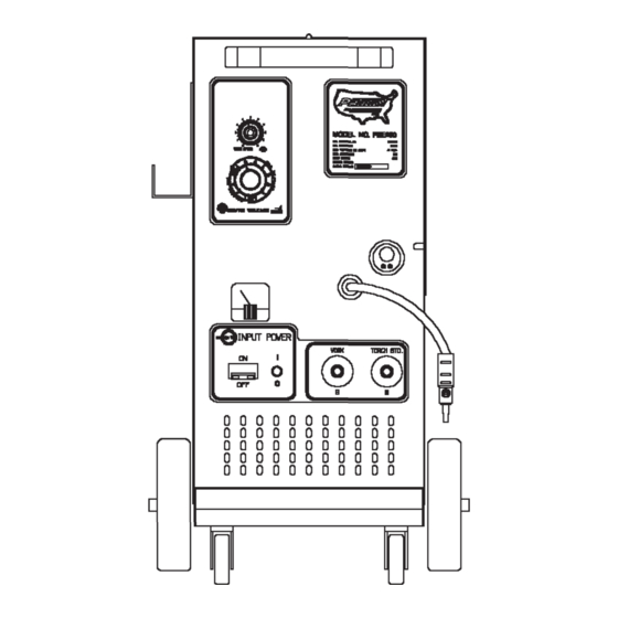
OPERATION WIRE FEED PRESSURE ROLL ADJUSTMENT The wire feed pressure roll is The following operating instruc- adjusted to the proper setting at tions and detailed setup procedures the factory, prior to delivery. It enable an operator without previous may be necessary to readjust the experience to produce quality fu- setting as components "seat in"... - Page 10 F. (-)NEGATIVE TERMINAL Negative output terminal. The following controls are lo- work cable is plugged into this cated on the front of the PBE250. terminal during standard weld- ing operation. The torch selec- tor cable can be plugged into WIRE...
- Page 11 WELDING NOTE Optimum control settings will When welding steel, the ideal vary according to the thickness of position for holding the torch metal, type joint, is inclined approximately 30 operator preference, etc. Best degrees towards the direction results can be obtained through of travel.
- Page 12 CONTINUOUS WELDING 2. DO NOT spray any anti-spatter ON ALUMINUM material on the torch or base (Optional Nylon liner and 100% metal and DO NOT attempt to Argon shielding gas are required) lubricate the aluminum wire in any way. Weld contamination 1.
- Page 13 MIG SPOT WELDING ON STEEL (PBE250S ONLY) SPOTWELD PRESS NOZZLE NOZZLE NOTE FIRMLY MIG Spot Welding is NOT AGAINST WORK CONTACT recommended for aluminum. 1. Trim the electrode wire so the stickout from the contact tip will be flush with the nozzle face, and fit the spot nozzle in SPOTWELD WORK...
-
Page 14: Maintenance
OPERATING HINTS The frequent use of anti-spatter spray will help prevent the adher- BURN BACK ence of spatter to the torch compo- nents. In the event the welding wire NOTE burns back into the contact tip: DO NOT use any anti-spatter 1. - Page 15 CUSTOMER SPARE PARTS bustibles, helper "watcher" should stand by with The Systematics PBE250 is a ma- a fire extinguisher or other chine of proven design and relia- fire protective device. bility. Following is a list of consumable...
-
Page 16: Trouble Shooting Chart
The Trouble Shooting Chart is a guide in identifying and correcting possible troubles which may occur when operating this equipment. FAULT POSSIBLE CAUSE REMEDY EQUIPMENT MALFUNCTION No main power, PBE250 switch is "OFF". Turn switch "on". (CB1) fan does not Wall breaker is "tripped". Reset wall breaker. operate, "Open"... - Page 17 TROUBLE SHOOTING (Cont.) (SYMBOL*) FOR TECH. SERVICE, CALL 1-610-696-9040 FAULT POSSIBLE CAUSE REMEDY EQUIPMENT MALFUNCTION (Cont.) Main power on, Loose torch thumb screw. Tighten thumb screw. torch Broken or loose connection. Check cables for trigger continuity. activated, Repair or tighten no welding connections.
- Page 18 TROUBLE SHOOTING (Cont.) (SYMBOL*) FOR TECH. SERVICE, CALL 1-610-696-9040 FAULT POSSIBLE CAUSE REMEDY FAULTY WELDS (Cont.) "Birdnesting" Excessive feed roll tension. Reduce tension. See page (Wire wrapping around drive Poor alignment. Make sure wire is rolls) properly aligned across roller. Oversize contact tip.
- Page 19 TESTING AND REPLACING DIODES 3. If all the diodes check out satisfactorily with the Volt- Silicon diodes have proven to be Ohm Meter, a load check must be highly reliable. However, weld made. This is easily accom- spatter build-up in the torch can plished using twelve...
- Page 20 WIRE FEED CALIBRATION Due to INPUT LINE VOLTAGE varia- tions supplied to the welding ma- chine. The WIRE FEED SPEED should be checked for proper operation. TO CHECK TRIM RESISTOR 1. Remove any tension on the drive roll. 2. Turn the wire speed dial (on the front of the machine) to "0".
-
Page 21: Connecting Tig Pack Or Spool Gun
PARTS BREAKDOWN - 15 SERIES MIG TORCH (Cont.) PART NO. DESCRIPTION (SYMBOL) TORCH NECK GROUP M3-101B ..TORCH NECK * M3-402 M3-402 M3-112 ..NECK INSULATOR M3-119 ..LOCK SCREW - SWITCH HOUSING M3-120 ..FERRULE * M1-401 M3-200B ..SWITCH ASSEMBLY CONSISTING OF: M3-201B .. -
Page 22: Liner Installation
THE TIG PACK WILL NOT WELD ALUMINUM. The TIG Welding Process is used to produce the highest quality, porosity-free welds. The TIG PACK adds TIG Welding capabilities to your Systematics Patriot MIG Welder. The TIG PACK is designed for Tungsten-Inert Gas (TIG) welding with Direct Current, Straight Polarity (DCSP) on steel, stainless steel, chrome-moly, copper or cast iron (18 Ga. -
Page 23: Parts Breakdown - Mig Torch
NOTES Systematics, Inc. West Chester, PA. 19380... - Page 24 NOTES Systematics, Inc. West Chester, PA. 19380...
-
Page 25: Options - Tig Pack Or Spool Gun
Systematics, Inc. West Chester, PA. 19380...