
Subscribe to Our Youtube Channel
Related Manuals for Newport iServer Series


Summary of Contents for Newport iServer Series
- Page 1 Ethernet Server Operator’s Manual NEWPORT Electronics, Inc. ® http://www.newportUS.com/iServer...
- Page 2 It is the policy of NEWPORT to comply with all worldwide safety and EMC/EMI regulations that apply. NEWPORT is constantly pursuing certification of its products to the European New Approach Directives. NEWPORT will add the CE mark to every appropriate device upon certification.
-
Page 3: Table Of Contents
TABLE OF CONTENTS Part 1: Introduction ...................2 Safety and EMC Considerations ..........2 Before You Begin .................3 Description ...................4 Part 2: Hardware ...................5 Physical Characteristics and Mounting of DIN Rail Unit ..5 Front Panel of DIN Rail Unit ............6 Rear Panel of iSeries Meter with iServer Built-in PCB ....6 Serial Communication Interfaces ..........8 2.4.1 Wiring RS232 Interface ...........9 2.4.2 Wiring RS485 Interface ..........10... - Page 4 Part 6: Specifications ..................30 Part 7: Factory Preset Values ................31 Part 8: Approvals Information .................32 Electromagnetic Compatibility (EMC) ........32 ..................32 Appendix A Glossary ..................33 Appendix B IP Address .................34 Appendix C IP Netmask .................35 Appendix D ASCII Chart ................36 ASCII Chart Control Codes ............37 LIST OF FIGURES: Figure 1.1 iServer on the Ethernet Network ..........4...
- Page 5 NOTES, WARNINGS and CAUTIONS Information that is especially important to note is identified by following labels: • NOTE • WARNING or CAUTION • IMPORTANT • TIP NOTE: Provides you with information that is important to successfully setup and use the Programmable Digital Meter. CAUTION or WARNING: Tells you about the risk of electrical shock.
-
Page 6: Part 1: Introduction
PART 1 INTRODUCTION 1.1 Safety and EMC Considerations The instrument is a Class III device (10 to 32 VDC). Always use a power supply, which complies with EN 60950 safety standard. EMC Considerations • Whenever EMC is an issue, always use shielded cables. •... -
Page 7: Before You Begin
1.2 Before You Begin Inspecting Your Shipment: Remove the packing slip and verify that you have received everything listed. Inspect the container and equipment for signs of damage as soon as you receive the shipment. Note any evidence of rough handling in transit. Immediately report any damage to the shipping agent. -
Page 8: Description
1.3 Description This device can be purchased as a stand alone DIN Rail mounted unit, or as an option for an iSeries monitor/controller (Embedded Ethernet Server) with a RS485 communication port interface. Some iSeries monitors/controllers do not utilize RS485 communications. In such models, the RS485 instructions do not apply. -
Page 9: Part 2: Hardware
PART 2 HARDWARE 2.1 Physical Characteristics and Mounting of DIN Rail Unit Figure 2.1 iServer Dimensions and Mounting Mounting on DIN Rail (refer to the Figure 2.1) To install unit onto DIN Rail: a) Tilt unit, position adapter guide onto DIN Rail. b) Push unit towards DIN Rail and it will snap into place. -
Page 10: Front Panel Of Din Rail Unit
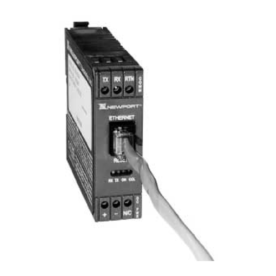
2.2 Front Panel of DIN Rail Unit Figure 2.2 Front Panel View of the iServer DIN Rail Unit... -
Page 11: Table 2.1 Front Panel Annunciators
Table 2.1 Front Panel Annunciators Serial Communication Interface Section: Transmit Wire connection (-Rx/-Tx for RS485 interface) Receive Wire connection (+Rx/+Tx for RS485 interface) Return, Common Ground Wire connection Network Communication Interface Section: Ethernet RJ45 Female Connector for 10BASE-T connection Reset Reset button used to change an IP Address and reset to the default password LED (Green) Flashing: Indicates transmission from the Serial port... -
Page 12: Serial Communication Interfaces
2.4 Serial Communication Interfaces Two communication interfaces are supported in the iServer: RS232 and RS-485. These standards define the electrical characteristics of a communication network. The RS485 port of the iServer is fully compatible for use with RS422 instruments. The RS485 is an extended version of the RS422 communication standard which increases the allowable number of devices from 10 to 32 by improving the electrical characteristics. -
Page 13: Wiring Rs232 Interface
2.4.1 Wiring RS232 Interface RTN TX RX Figure 2.4 Wiring between the iServer Serial Port and Device with RS232 Port Table 2.3 shows the pin connection assignments between the iServer serial port and device with RS232 serial communication interface. Table 2.3 iServer DEVICE WITH RS232 Tx (Transmit) -
Page 14: Wiring Rs485 Interface
2.4.2 Wiring RS485 Interface RS485 interface uses a two-wire communication system (one for transmitting and one for receiving) plus a common wire to connect to the shield of the cable. It is recommended to use a shielded cable with one twisted pair. Use of twisted pair and shield will significantly improve noise immunity. -
Page 15: Network Communication Interfaces
2.5 Network Communication Interfaces 2.5.1 10Base-T RJ-45 Pinout The 10BASE-T Ethernet network (RJ-45) system is used in the iServer for network connectivity. The 10 Mbps twisted-pair Ethernet system operates over two pairs of wires. One pair is used for receiving data signals and the other pair is used for transmitting data signals. -
Page 16: Part 3: Network Configuration
PART 3 NETWORK CONFIGURATION 3.1 Network Protocols The iServer can be connected to the network using standard TCP/IP protocols. It is also supported by ARP and HTTP protocols. TCP/IP networking protocols are superimposed into a local Ethernet network until, if so desired, a connection is made to the Internet. -
Page 17: Default Ip Address
3.3.1 Default IP Address The iServer is shipped with a default IP address set to 128.100.101.254. If you are going to use a Web browser or HTTPGET program to access the device, make sure that the default IP address is available to the instrument before processing. If the factory default address is already in use in your network, use the Ethernet crossover cable connected to one computer to access the device and modify the IP address from factory defaults. -
Page 18: Part 4: Serial Interface Configuration
PART 4 SERIAL INTERFACE CONFIGURATION An industrial device with serial interfaces (PLC, CNC controllers, PC, Data Display Devices, etc.) can be connected to the serial port of the iServer. 4.1 Communication Protocol A data communication protocol defines the rules and structure of messages used by all devices on a network for data exchange. - Page 19 Where: "*" is the selected Recognition Character. You may select any ASCII table symbol from "!" (HEX address "21") to the right-hand brace (HEX "7D") except for the caret "^", "A", "E", which are reserved for bus format request. "ccc" stands for the hex-ASCII Command Class letter (one of eleven given in Table 4.1), followed by the two hex-ASCII Command Suffix characters identifying the meter data, features, or menu items to which the command is directed.
-
Page 20: Part 5: Operations
PART 5 OPERATIONS 5.1 Modifying the IP Address The IP Address may be set via the network by using "Setip" DOS program. The setip.exe file is used to set a new IP Address. This file will be automatically installed when you run any iServer related software available on our website and CD. Example to use the "setip"... - Page 21 For example: C:\iServer\Setip\setip 0A:0C:3D:0B:0A:0B 128.100.101.33 for MAC address in Hexadecimal C:\iServer\Setip\setip 10.12.61.11.10.11 128.100.101.33 for MAC address in decimal 6. Make sure that the iServer has a new IP address by pinging the new IP address C:\ping 128.100.101.33 If you got the following respond, it means that your device now has the new IP address: Pinging 128.100.101.33 with 32 bytes of data.
-
Page 22: Httpget Program
5.2 HTTPGET Program You can setup and read the information from the iServer by using the HTTPGET program. The following program can be used to read data from the embedded server firmware by using TCP port 1000. The command string sends to this TCP port, then it reads back the response from the same port. -
Page 23: Arp Protocol
5.3 ARP Protocol ARP is the Internet layer protocol responsible for determining the MAC (hardware) address that corresponds to a particular IP address. The ARP command allows the user to view the current contents of the ARP cache of the local computer (residing on the same network) or remote computer (residing on the different network) through a router. -
Page 24: Figure 5.1 Arp -A Commands And Responses
Figure 5.1 below shows examples of arp commands and responses. You computer has an IP address 128.100.101.118. The destination computer has an IP address 128.100.101.96 Figure 5.1 arp –a Commands and Responses... -
Page 25: Setup And Operation Using The Iserver Web Page
5.4 Setup and Operation using the iServer Web Page This home page is designed for our company product using iSeries serial communication protocol. It can be utilized for other products using the standard RS232/485 communication interface. 1. Start your Web browser (Internet Explorer 5.0 or Netscape Navigator 6.0). 2. -
Page 26: Read Devices
This home page provides the following features: 5.4.1 Read Devices: • Read variables from up to four different devices. • Read up to four variables from the same device. • Manually or automatically update readings from your devices. Set time interval for Auto Update. -
Page 27: Send Raw Command
If access to the menu item is restricted (untrusted host), the user will be prompted for a password number. In order to proceed to the "Device Setpoints" submenu, the user should enter the correct password for access level "1" (operator level) or access level "0" (administrator level). -
Page 28: Serial Port Configuration
• Up to four different devices or parameters can be modified. 5.4.4 Serial Port Configuration • Allows the user to adjust serial communications settings of the instrument. • When connecting your instrument to the iServer, the communications parameters must match. -
Page 29: Configure Access Control
5.4.5 Configure Access Control • Allows the network administrator to set a different access level to the iServer parameters for the different groups or individual users. There are three different access levels: 1. Access Level "0" (administrator level) allows certain groups and individual users to access and modify "All"... -
Page 30: Log In
5.4.6 Log In • Allows the user to access the menu items of the iServer Home page according to their access level. Except for "Read Device", if user attempts to advance to the menu items, they will be prompted to enter the password only once to open the menu items. 5.4.7 Change ID •... -
Page 31: Mail Notifier Software
5.5 Mail Notifier Software For complete information of how to use the Mail Notifier software, click on the Help menu of the main window. The Mail Notifier software utilizes E-Mail notifications of alarm conditions of the devices having either embedded iServer board or connected via the stand alone iServer units, which reformats RS232/485 bus traffic into Ethernet packets. -
Page 32: Program Options Setup And Configuration
5.5.2 Program Options Setup and Configuration Complete program setup requires: • Entering a recipient for the E-Mail • Specifying connection details to MAPI services. • Defining alarms for devices, and selecting how and when the E-Mail will be active. Figure 5.4 iServer Mail Notifier Profile Setup The E-Mail User tab provides fields to define the name/profile for the Mail Notifier to utilize when E-Mail is sent. -
Page 33: Device Setting Setup And Configuration
5.5.3 Device Setting Setup and Configuration Device setup requires: • Entering the IP address for iServer device (for example 128.100.101.98). • Specifying Socket number (1000 for iServer). • Defining RS485 Unit # serial interface address (1 to 199). Enter "0" for RS232 interface. -
Page 34: Part 6: Specifications
PART 6 SPECIFICATIONS Standards Compliance Environmental Conditions IEEE 802.3 10Base-T 0° to 50°C (32° to 122°F), 90% RH Supported Protocols Case TCP/IP, ARP, HTTPGET Plastic case for DIN rail mounting Serial Interface Dimensions Communication Standard: RS232, RS485, 76.2 (3.00") H x 22.9 (0.90") RS422 W x 111.76 (4.40") D mm Transfer speed (Baud rate): 2400, 4800,... -
Page 35: Part 7: Factory Preset Values
PART 7 FACTORY PRESET VALUES PRESET PARAMETERS FACTORY DEFAULTS NOTES Network Interface: IP address 128.100.101.254 Serial Interface: Communication Standard RS485 Transfer Speed 9600 bps Bad Parity accepted Parity Timeout 750 msec... -
Page 36: Part 8: Approvals Information
PART 8 APPROVALS INFORMATION 8.1 Electrical Compatibility (EMC) This device comforms with requirements of EMC Directive 89/336/EEC, amended by 93/68/EEC. This instrument complies with the following EMC Immunity Standards as tested per EN 50082-2, 1995 (Industrial environment) Phenomena Test Specification Basic Standard Electrostatic +/- 4 kV contact discharge... -
Page 37: Appendix Aglossary
APPENDIX A GLOSSARY User of this manual should be familiar with following definitions: ARP (Address Resolution Protocol) is a protocol for mapping an Internet Protocol address (IP address) to a physical machine address that is recognized in the local network. For example, the IP address in use today is an address that is 32-bits long. In an Ethernet local area network, however, addresses for attached devices are 48-bits long. - Page 38 Appendix B IP Address An IP address is a unique 32-bit address assigned to a computer and includes: • A network ID number identifying a network. • A host ID number identifying a computer on the network. All IP addresses have been divided into three smaller groups (classes) A, B and C •...
-
Page 39: Appendix C Ip Netmask
Appendix C IP Netmask IP Netmask or Subnet Mask is a 32-bit pattern of ones and zeros used to determine network portion of an IP address from the host portion of the IP address. Subnet mask is a network ID that is created by borrowing bits from host portion of IP address and using them as part of a network ID. -
Page 40: Appendix Dascii Chart
Appendix D ASCII Chart ASCII Binary ASCII Binary Char No Parity Char No parity 00000000 01000000 00000001 01000000 00000010 01000010 00000011 01000011 00000100 01000100 00000101 01000101 00000110 01000110 00000111 01000111 00001000 01001000 00001001 01001001 00001010 01001010 00001011 01001011 00001100 01001100 00001101 01001101 00001110... -
Page 41: Ascii Chart Control Codes
Appendix D ASCII Chart Continuation 00101111 01101111 00110000 01110000 00110001 01110001 00110010 01110010 00110011 01110011 00110100 01110100 00110101 01110101 00110110 01110110 00110111 01110111 00111000 01111000 00111001 01111001 00111010 01111010 00111011 01111011 < 00111100 01111100 00111101 01111101 > 00111110 01111110 00111111 01111111 ASCII Control Codes ASCII Dec Hex Ctrl Key... - Page 42 NOTES...
- Page 43 Warranty/Disclaimer NEWPORT Electronics, Inc. warrants this unit to be free of defects in materials and workmanship for a period of one (1) year from the date of purchase. In addition to NEWPORT’s standard warranty period, NEWPORT Electronics will extend the warranty period for four (4) additional years if the warranty card enclosed with each instrument is returned to NEWPORT.
- Page 44 Newport Electronics GmbH Daimlerstrasse 26 • D-75392 Deckenpfronn • Germany TEL: 49 7056 9398-0 • FAX: 49 7056 9398-29 Toll Free: 0800 / 6397678 • http://www.newport.de • e-mail: sales@newport.de Newport Electronique S.A.R.L. 9, rue Denis Papin • 78190 Trappes • France TEL: +33 130 621 400 •...
Need help?
Do you have a question about the iServer Series and is the answer not in the manual?
Questions and answers