
Summary of Contents for Mente Marine ACS R/RP
- Page 1 ACS R/RP Attitude Control System User’s manual Mente Marine Vaasa, Finland info@mente-marine.com www.mente-marine.com...
-
Page 2: Table Of Contents
Calibration ..........................9 Verify connection......................... 10 Usage ............................ 11 Attitude setting ...............................11 Fine adjustment ..............................11 Adjusting gain ................................12 Retraction................................12 Shut down ................................12 Specifications........................13 Troubleshooting........................14 Indicators ................................14 Supply voltage ...............................14 Warranty policy ........................15 2014 Mente Marine. All rights reserved. -
Page 3: Introduction
Introduction This user’s manual describes the installation and usage of the ACS RP attitude control system from Mente Marine. It is available in print and in Pdf format at www.mente-marine.com Symbols and abbreviations Attitude Control System Light Emitting Diode Security Switch off the main circuit breaker or put the ACS into manual mode before lifting or transporting the boat. -
Page 4: Theory Of Operation
Theory of operation The deep-V hulls of modern pleasure boats are designed to provide you with a smooth ride in rough water. The deeper the V, the more need for trim tabs to keep the boat levelled. A Roll or sideward’s inclination is dependent on the wind and passenger location. -
Page 5: Adaptive System
Adaptive system ACS adapts to boats over the whole range. Thanks to the adaptive functionality, the boat is set up to the optimum running attitude, taking into account differences in size and trim tab performance. It also adapts to varying sea conditions. In calm seas, a list condition is corrected faster than in rough seas. -
Page 6: Installation
Installation ACS R and ACS RP have built-in sensors that measure the boat’s movements and should therefore be mounted upright or laying down. All angles between upright and laying down are allowed. 1) Upright 2) 3) Between upright and laying down 4) Laying down Regardless of the mounting angle, the starboard button should face the starboard side of the boat and the port button the port side. -
Page 7: Connection
Connection IMPORTANT! In retrofit installations, disconnect the wires from the old control panel before connecting the ACS. It should not be connected in parallel with the old panel. Switch off the main circuit breaker before starting the connection! Hydraulic trim tabs Hydraulic trim tabs, such as Bennett, Instatrim, QL and Trimmaster use a hydraulic pump unit to extend and retract the actuators. -
Page 8: Electromechanical Trim Tabs
Electromechanical trim tabs Connect the starboard actuator to terminals 5 and 6 and the port actuator to terminals 3 and 4, according to the figure that follows. Verify the connection later on and change it if necessary. Lenco Lectrotab Ultraflex marking Black (port) White (port) -
Page 9: Calibration
Calibration For the ACS to operate properly, it needs to know the trim tab type, position, and current consumption. This information is automatically acquired and stored in memory during calibration. Before you start, ensure that no obstacles hinder the free run of the tabs. The AUTO indicator blinks to indicate that calibration is needed. -
Page 10: Verify Connection
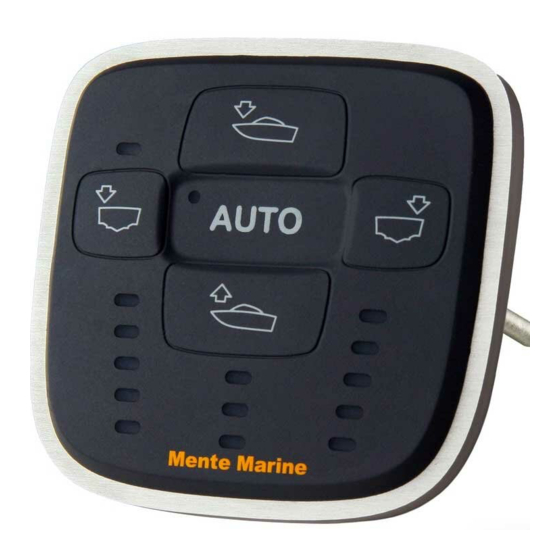
Verify connection IMPORTANT! After calibration, verify the connection by pressing the buttons one by one and observing the trim tabs. Check the actual movement of the tabs at the transom. For the automatics to work properly, the trim tabs have to move in the correct direction when controlling them manually. The uppermost button controls both tabs down- wards. -
Page 11: Usage
Usage Attitude setting Run the boat at cruising speed. Manually control the trim tabs until you find the best attitude. Then, press and hold the auto button for 4 s until the AUTO indicator is lit Now, the attitude is stored in the memory, and the ACS is set in the automatic mode. -
Page 12: Adjusting Gain
Adjusting gain The gain determines how fast the ACS should correct a list condition. It can be adjusted in three steps and the default setting is step I. Step II provides a correction that is a little faster, while step III is the fastest. -
Page 13: Specifications
Specifications Compliance Bennett, Instatrim, Trimmaster, QL Volvo Penta, TFX Teleflex, TX Controls (Hydraulic tabs) Compliance Lectrotab, Lenco, Eltrim, Ultraflex (Electromechanical tabs) ACS R Control in the roll axis ACS RP Control in the roll and pitch axes Boat length 15...40 feet Tab type detection Automatic Gain... -
Page 14: Troubleshooting
Troubleshooting If a fault is found, an indicator will start to blink intensively. Indicators Trim tabs not found Wrong installation angle Check the connection! Short-circuit to the positive side Short-circuit to ground Supply voltage During a fraction of a second, when starting a trim tab motor, the current is much higher than normal and the supply wires, fuseholder and battery should be in a good condition. -
Page 15: Warranty Policy
Warranty policy All ACSs (Attitude Control Systems) purchased through authorized distribution channels are guaranteed against defects of material or workmanship for a period of 24 months from date of purchase. Service will be rendered, and defective parts will be replaced without cost to you within that period, provided that the equipment does not show any evidence of an impact, liquid damage, mishandling, tampering, or chemical corrosion, operation contrary to operating instructions, or modification by an unauthorized repair shop. - Page 16 Elektro-Navigation Schick & Co. GmbH Siemensstr. 35 - 25462 Rellingen Tel.: 04101/301 01 - Fax: 04101/301 333 info@ferropilot.de - www.ferropilot.de Copyright Mente Marine...
Need help?
Do you have a question about the ACS R/RP and is the answer not in the manual?
Questions and answers