
Summary of Contents for BeON ECO
- Page 1 User Manual V1.1 User Manual V1.1 User Operating Manual Installation Operation Address: R. Actriz Palmira Bastos, LT 102 Lisbon Telephone: +351 935866092 Email: info@beonenergy.com Skype: beonenergy web: www.beonenergy.com...
- Page 2 Catalog The micro inverter offers unique technology that enables much improved solar energy harvest, increased reliability, simplified installation and efficient management of solar power systems. Each micro inverter is individually connected to one PV module in the solar panel array. This unique configuration achieves Maximum 1 Important Safety Information Power Point Tracking (MPPT) at the PV module level, thus 1.1 Read It First...
-
Page 3: Important Safety Information
markings in the technical description and on the micro inverter system and the PV 1 Important Safety Information equipment. Connect the micro inverter to the utility grid only after you have completed all installation procedures and after receiving prior approval from the electrical utility 1.1 Read It First company. -
Page 4: Optimal Reliability
2 Micro Inverter System 2.3 Easy of Design The micro inverter system is the world s most technologically advanced inverter system for use in utility-interactive applications. This manual details the safe PV systems using micro inverters are very simple to design and install. You will not installation and operation of the micro inverter. -
Page 5: Product Information
3.3 Datasheet 3 Product Information Model BeON ECO Input Data (DC) 3.1 Overview Max. input power 180-300W Max. input DC voltage [ V ] Start Voltage 24 V Peak power tracking range 24V~50V Operating range 22V~50V Max. DC short circuit current Max. -
Page 6: Packing Checklist
5 Planning of Micro Inverter Installation 4 Packing Checklist 4.1 Assembly Parts 5.1 Explanations of Symbols on Inverter After you receive the micro inverter, please check if there is any damage on the Symbol carton, and then check the inside completeness for any visible external damage on Description the micro inverter or any accessories. -
Page 7: Installation Diagram
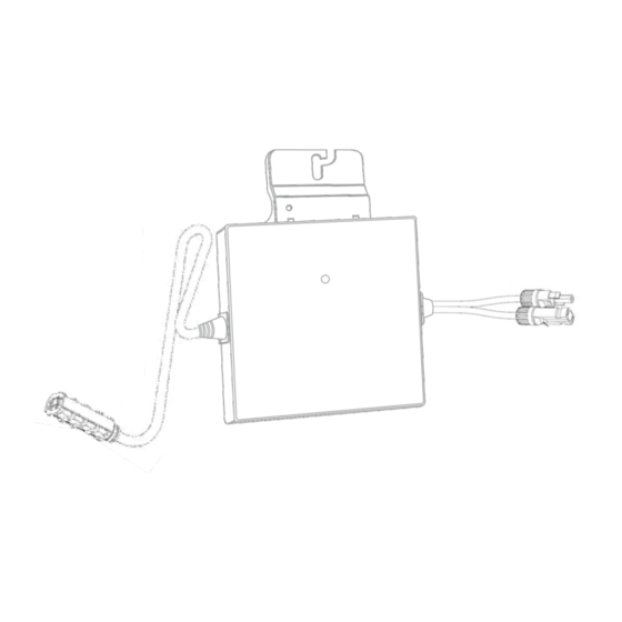
6 Micro Inverter Mounting and Wiring 6.1 Tool Required 6.2 Installation Diagram 01. PV module 02 .Micro inverter 03 .Junction box 04. Mounting rail 6.3 Installation Steps 05 .Grounding line 06 .AC power cable Installing the micro inverter system involves several key steps. Each step listed here is detailed in the following page. - Page 8 Strip cable jacket 18mm~25mm WARNING Allow a minimum of 1.9cm between the roof and the bottom of the micro inverter. Also allow 1.3cm between the back of the PV module and the top of the micro inverter. Disassemble the Seal, Clamp Ring, Nut, then Insert through the cable WARNING You must install the micro inverter under the module, out of rain and sun.
-
Page 9: Commissioning And Operation
8 Troubleshooting and Maintenance 7 Commissioning and Operation Please notice the symbols. Adhere to all the safety measures described throughout this manual. Qualified personnel can use the following troubleshooting steps if the PV system does not operate correctly. WARNING Qualified personnel only may connect the micro inverter to WARNING the utility grid after receiving prior approval from the electrical utility company. -
Page 10: Troubleshoot An Inoperable Micro Inverter
8.2 Troubleshoot an Inoperable Micro Inverter Disconnect and re-connect the DC PV module connectors. The status LED of each micro inverter will blink green to indicate normal start-up operation soon To troubleshoot an inoperable micro inverter, follow the steps in the order shown. after DC power is applied.
Need help?
Do you have a question about the ECO and is the answer not in the manual?
Questions and answers