
Related Manuals for RTA 490NBX


Summary of Contents for RTA 490NBX
- Page 1 490NBX – ASCII to PLC Gateway Product User Guide Software Build Date: May 27 , 2015 Version 3 Real Time Automation, Inc. 1-800-249-1612...
- Page 2 Trademarks CompactLogix, ControlLogix, & PLC-5 are registered trademarks of Rockwell Automation, Inc. EtherNet/IP is a trademark of the ODVA. MicroLogix, RSLogix 500, and SLC are trademarks of Rockwell Automation, Inc. Microsoft, Windows, and Internet Explorer are registered ® trademarks of Microsoft Corporation. BACnet is a registered trademark of American Society of Heating, Refrigerating and Air-Conditioning Engineers (ASHRAE).
-
Page 3: Table Of Contents
Overview ............................... 5 Getting Started .............................. 6 Powering the 490NBX ..........................6 Accessing the Main Page..........................7 Main Page Does Not Launch ......................... 8 Committing Changes to the Settings ......................9 Main Page ..............................10 Device Configuration ........................... 11 PLC Configuration............................12 Client TCP/IP Communication Setup ...................... - Page 4 Download Firmware ..........................27 Reset Gateway ............................27 Save and Replace Configuration using SD Card ..................28 Data Transfer To/From SD Card ......................28 Using IP Setup with SD Card ........................28 Completing the Installation......................... 29 Appendix A: Error Definitions ........................30 Appendix B: I/O Messaging - Configuration (Rev 7.03 or Later) ..............
-
Page 5: Overview
Overview The 490NBX gateway seamlessly connects up to 10 Ethernet TCP/IP devices to a ControlLogix, CompactLogix, FlexLogix, MicroLogix, PLC5E, SLC, or other legacy PLC featuring a NetENI module. By following this guide, you will be able to configure the 490NBX gateway. -
Page 6: Getting Started
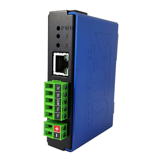
Server or Client o IP Address o Port Number Powering the 490NBX • Connect a 12-24VDC power source to the 2-pin terminal on the router. o The unit draws 175 mA at 12VDC o The router has a voltage operating range from 12-24VDC. -
Page 7: Accessing The Main Page
Accessing the Main Page The following steps will help you access the browser based configuration of the 490NBX. 1) Insert the provided CD-ROM into a computer also on the network. 2) Run the IPSetup.exe program from the CD-ROM. 3) Find unit under “Select a Unit”. -
Page 8: Main Page Does Not Launch
An invalid IP Address would be: 169.254.x.x 2) The gateway must be on the same Network/Subnet as the PC Once you have both devices on the same network, you should be able to ping the 490NBX using a MS- DOS Command Prompt. -
Page 9: Committing Changes To The Settings
Committing Changes to the Settings Changes made to the settings of the gateway will not take effect until the gateway is restarted. • a) Changes will not be stored if the gateway’s power is removed prior to rebooting. b) The gateway detects changes and will prompt you with a red notice box to restart the gateway after change. -
Page 10: Main Page
Main Page The main page is where important information about your gateway and its connections are displayed. Navigation (green box below): You can easily navigate between pages (Main, Configuration, Diagnostics, and Other pages) using the buttons on the left hand side. Device Status (orange box below): This quickly shows the high-level status of any TCP/IP ports that are enabled in the TCP/IP... -
Page 11: Device Configuration
Device Configuration 1) From the main page, click the Edit button which is located next to Device Configuration. 2) This allows you to edit the Device Description, IP Address, Subnet, Default Gateway and Ethernet Link settings. 3) To save all values, click the Save Parameters button. Real Time Automation, Inc. -
Page 12: Plc Configuration
PLC Configuration 1) Click the PLC Configuration button under the CONFIGURATION section. 2) PLC Type: Select which PLC you are using. a. If using a Logix PLC, all processors are compatible. b. If using a PLC5E, then it must be: Series C, Revision N.1 or later; Series D, Revision E.1 or later;... - Page 13 b. If set to 0, the gateway will communicate as fast as possible to the PLC and generate the most traffic. c. In applications with a heavy network, it is recommended that you increase this delay to limit network traffic. 7) Heartbeat Tag/File: This Tag or File will act as an incremental counter for messages passed though the gateway.
-
Page 14: Client Tcp/Ip Communication Setup
Client TCP/IP Communication Setup 1) From any page, click the TCP/IP Configuration button under the CONFIGURATION section. If the Gateway is a Client Connecting to a Server Device 2) Enable: Check this box to enable any of the 10 possible ports. a. -
Page 15: Server Tcp/Ip Communication Setup
Server TCP/IP Communication Setup 1) From any page, click the TCP/IP Configuration button under the CONFIGURATION section. If a Client Device is Connecting to the Gateway Acting as a Server 2) Enable: Check this box to enable any of the 10 possible ports. a. -
Page 16: Setting Up Ascii To Plc Communication
Setting up ASCII to PLC Communication 1) Click the ASCII Configuration button under the CONFIGURATION section. 2) Check the Enable Communication checkbox to modify the fields below. 3) Data Type: Select the Data Type for the Tag / File Name that you defined in the PLC. a. -
Page 17: Message Queue
iii. For Controllers using RSLogix 5000, the range for each data type is: ♦ STRING/INT/SINT: 0-4096 characters ♦ STRING– If using more than 82 characters, a User Defined Data Type must be created within the PLC and used. Refer to Appendix C for instructions. -
Page 18: Setting Up Plc To Ascii Communication
Setting up PLC to ASCII Communication 1) Click the ASCII Configuration button under the CONFIGURATION section. 2) Check the Enable Communication checkbox to modify the fields below. 3) Data Type: Select the Data Type for the Tag / File Name that you defined in the PLC. a. - Page 19 i. STRING: 0-82 characters ii. INT: 0-200 characters iii. SINT: Not Used 6) Delimiters: Configure the characters to add to the message. a. Start Delimiter Count: Use this feature to add a common starting delimiter(s) to messages being sent to the ASCII device. i.
-
Page 20: Diagnostics And Troubleshooting
Connection Retry Delay: Connection is not established. Verify that the 490NBX and PLC are on the same network. Connected: Good communication with the PLC. Connection Attempts: This value increments every time the 490NBX loses connection to the PLC and attempts to reconnect. Write Heartbeat to PLC: OK: Number of successful write messages to heartbeat Tag/File Name. -
Page 21: Diagnostics And Troubleshooting - Ascii To Plc
Current message being processed (bytes): This buffer shows the real time data that the ASCII device is sending out to the 490NBX gateway. All data in this buffer is pending due to one of the three end cases not being met. -
Page 22: Diagnostic Counters
Error: Increments when there is an error with the Tag/File in the PLC. Last Error: This will report the most recent error. Note: Errors that show up here are reported from either the 490NBX or the PLC. For detailed errors and explanations, please see... -
Page 23: Diagnostics And Troubleshooting - Plc To Ascii
Tag/File Name in the PLC. Last Error: This will report the most recent error found. Note: Errors that show up here are reported from either the 490NBX or the PLC. For detailed errors and explanations, please see... -
Page 24: Led Behavior
LED Behavior When both LEDs blink Red alternating like railroad crossing lights, the gateway’s configuration has been changed and is expecting a reboot. LED 1 : ASCII Blink No messages sent or received. Green Solid All TCP Connections are valid and are communicating Green to the gateway within the Inactivity Timeout configured. -
Page 25: Save/Load The Configuration
4) Save this file to the PC. Load the Saved Configuration 1) Click Choose File and search for the configuration to load to the 490NBX. 2) Click Load Configuration. If successful, you will be redirected to the main page and be forced to reboot the gateway. -
Page 26: Utilities
Various options to reset the gateway. Logging Most users will not need to do anything with this feature. If there are problems with the 490NBX, a RTA Technical Support Specialist will direct you in how to use this feature. Security Configuration To configure security for a single username and password, click the Utilities button under the OTHER navigation pane and then click the Security button. -
Page 27: Security - Log In
Reset Gateway There are 3 options to reset the gateway. • Restart the Gateway – Saves the current settings of the 490NBX and performs a software reboot. • Reset to Last Powerup – Brings the device back to its last power up settings. -
Page 28: Save And Replace Configuration Using Sd Card
Set button is pressed. This is intended as an extra precaution to ensure that the IP Address should be modified from what is currently stored in the SD Card. 1. Enter a UserName of RTA. 2. Enter a Password of RTA. -
Page 29: Completing The Installation
Completing the Installation You have now set up your 490NBX for communication and are ready to place the device in your application. If at any time you need further assistance do not hesitate to call Real Time Automation support. Support Hours are Monday-Friday 8am-5pm CST Toll free: 800-249-1612 Email: support@rtaautomation.com... -
Page 30: Appendix A: Error Definitions
Appendix A: Error Definitions Error Status Name Description Success Service was successful 0x00 0x01 Controller Slot Doesn’t Exist Connection related service failed along the connection path 0x02 Resource unavailable Resources needed for the object requested service were unavailable 0x03 Invalid parameter value See Error 0x20 0x04 Incorrect Tag Data Type... - Page 31 0x10 Device state conflict The device’s current mode/state prohibits the execution of the requested service 0x11 Reply data too large The data to be transmitted in the response buffer is larger than the allocated response buffer 0x12 Fragmentation of a primitive value The service specified an operation that is going to fragment a primitive data value 0x13...
- Page 32 0x1E Embedded server error An embedded service resulted in an error: This can mean the Controller Slot, IP Address or Tag Name does not match. The Tag is not defined in the Controller Scope within the PLC, or the Tag does not have Read/Write privileges.
- Page 33 0x29 Member not settable A request to modify a non-modifiable member was received 0x2C Attribute not gettable A request to read a non-readable attribute was received Real Time Automation, Inc. 1-800-249-1612...
-
Page 34: Appendix B: I/O Messaging - Configuration (Rev 7.03 Or Later)
Configuration page. Once you enable I/O Messaging, the Tag Name and Data Type in the ASCII to PLC and PLC to ASCII direction will not be used. 1. Set up the 490NBX as a Generic Ethernet Module into the Ethernet module I/O tree 2. Set the Data Format to “Data SINT”... -
Page 35: Input / Output Assembly Handshaking Breakdown
New messages from the 490NBX are only written to the PLC when the Input Sequence Number matches the Input Handshake. All other messages are queued in the 490NBX until the queue is full. Messages are then discarded based on the discard rules defined by the user. -
Page 36: Appendix C: Create User Defined Tag In Rslogix 5000
Appendix C: Create User Defined Tag in RSLogix 5000 1) Within RSLogix 5000, click on Data Types and select Strings. 2) Right click on String and select New String Type. Give the new data type a name. 3) Select the max number of characters to be transferred. 4) When creating the tag name in the PLC, select the name of the new user defined data type you just created.
Need help?
Do you have a question about the 490NBX and is the answer not in the manual?
Questions and answers