
Related Manuals for Toshiba RAS-M10YDV-E


Summary of Contents for Toshiba RAS-M10YDV-E
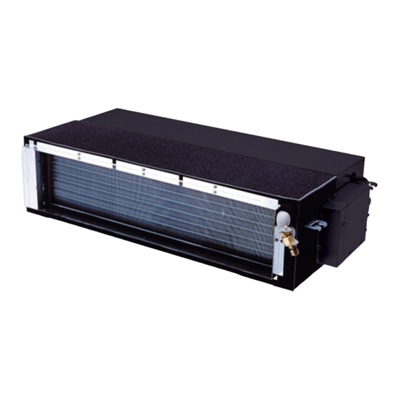
- Page 1 Heat Pump Model Cooling Only Model RAS-M10YDV-E RAS-M10YDCV-E RAS-M13YDV-E RAS-M13YDCV-E RAS-M16YDV-E RAS-M16YDCV-E R410A PRINTED IN JAPAN, Jul., 2002 ToMo...
-
Page 2: Table Of Contents
CONTENTS APPLICATION ......................... 2 1. PRECAUTIONS FOR SAFETY ..................3 2. SPECIFICATIONS ......................5 3. CONSTRUCTION VIEWS ....................7 4. WIRING DIAGRAM ......................8 5. SPECIFICATIONS OF ELECTRICAL PARTS ..............9 6. REFRIGERANT CYCLE DIAGRAM ................10 7. CONTROL BLOCK DIAGRAM ..................11 8. -
Page 3: Precautions For Safety
1. PRECAUTIONS FOR SAFETY For general public use Power supply cord of Outdoor unit shall be more than 2.5mm² (H07RN-F or 245 IEC66) polychloroprene sheathed flexible cord. • Read this “Precautions for Safety” carefully before servicing. • The precautions described below include the important items regarding safety. Observe them without fail. •... - Page 4 • Never modify this unit by removing any of the safety guards or by by-passing any of the safety interlock switches. • Exposure of unit to water or other moisture before servicing may cause a short circuit. Do not store it in a wet basement or expose to rain or water. •...
-
Page 5: Specifications
2. SPECIFICATIONS RAS-M10YDV-E, RAS-M13YDV-E, RAS-M16YDV-E (Heat Pump Model) Indoor unit model name RAS-M10YDV-E RAS-M13YDV-E RAS-M16YDV-E Cooling capacity (kW) Cooling capacity range (kW) Heating capacity (kW) Heating capacity range (kW) Power supply (Ø-V-Hz) 1Ø 220 – 240 V, 50 Hz / 220 V, 60 Hz Operation current 0.59... - Page 6 RAS-M10YDCV-E, RAS-M13YDCV-E, RAS-M16YDCV-E (Cooling Only Model) Indoor unit model name RAS-M10YDCV-E RAS-M13YDCV-E RAS-M16YDCV-E Cooling capacity (kW) Cooling capacity range (kW) Power supply (Ø-V-Hz) 1Ø 220 – 240 V, 50 Hz / 220 V, 60 Hz Operation current 0.59 Electric characteristics Power consumption Power factor Blower...
-
Page 7: Construction Views
3. CONSTRUCTION VIEWS 650 (Inside flange) Drain-up kit RB-F81E (Accessory sold separately) Drain piping connecting port (Nominal Ø20 Vinyl chloride pipe) Duct connecting flange (Require at site) 156.5 730 (Hanging bolt pitch) 24.5 Duct connecting flange Refrigerant pipe (Require at site) connecting port (Liquid side Ø6.35) 640 (Inside flange) -
Page 8: Wiring Diagram
4. WIRING DIAGRAM 1Ø TRANSFORMER AC220 –240V / 50Hz AC220V / 60Hz INFRARED RAYS RECEIVING AND EARTH INDICATING PARTS CONNECTION CABLE 3 4 5 1 2 3 4 5 1 2 3 CN11 CN17 CN04 CN03 EARTH INDOOR TERMINAL CN20 BLOCK CN05 FUSE... -
Page 9: Specifications Of Electrical Parts
5. SPECIFICATIONS OF ELECTRICAL PARTS 5-1. Indoor Unit Parts name Type Specifications Output (Rated ) 60W, 4 pole, 1 phase, 220 – 240, 50Hz/220, 60Hz Fan motor (for indoor) MF-200-60-4B M coil A coil Winding resistance (Ω) at 20°C 73.8 Thermo. -
Page 10: Refrigerant Cycle Diagram
6. REFRIGERANT CYCLE DIAGRAM RAS-M10YDV-E, RAS-M10YDCV-E RAS-M13YDV-E, RAS-M13YDCV-E INDOOR UNIT Evaporator • Multi-blade fan Connecting pipe Connecting pipe Thickness : 0.8mm Thickness : 0.8mm Ø9.52 Ø6.35 Sectional shape of heat insulator OUTDOOR UNIT RAS-M16YDV-E, RAS-M16YDCV-E INDOOR UNIT Evaporator • Multi-blade fan... -
Page 11: Control Block Diagram
Controller Drain Pump Relay Drain Pump Noise Filter Option Serial Signal Transmitter/Receiver From Outdoor Unit Serial Signal Communication Remote controller RAS-M10YDV-E, M13YDV-E, M16YDV-E RAS-M10YDCV-E, M13YDCV-E, M16YDCV-E (Heat Pump Model) (Cooling Only Mpdel) Infrared Infrared Rays Rays Wireless Remote Controller Wireless Remote Controller... -
Page 12: Operation Description
8. OPERATION DESCRIPTION 8-1. Outline of Air Conditioner Control (2) Role of outdoor unit controller Receiving the operation command signal (Serial This air conditioner is a capacity-variable type air signal) from the indoor unit controller, the outdoor conditioner, which uses AC motor for the indoor fan unit performs its role. - Page 13 (4) Contents of operation command signal (Serial 8-1-2. Current Release Control signal) from outdoor unit controller to indoor unit The outdoor main circuit control section (Inverter controller assembly) detects the input current to the outdoor The following signals are sent from the outdoor unit.
-
Page 14: Description Of Operation Circuit
8-2. Description of Operation Circuit 8-2-2. Cooling Operation (The Remote controller MODE Button • Turning [ON] the breaker flashes the operation is Set to the COOL Position) lamp. • Once the setting is made, the operation mode is This is the display of power-ON (or notification of memorized in the microcomputer so that the same power failure). - Page 15 (2) Prevent-freezing control (1) Dehumidifying-preferential Cooling capacity control If temperature of indoor heat exchanger detected by the indoor heat exchanger sensor is 4°C or • The cooling capacity and room temperature are lower, compressor motor speed is gradually controlled by changing the compressor motor lowered to prevent freezing of the indoor heat speed according to both the difference between the exchanger.
- Page 16 [Cold draft preventing control] (3) Defrost control 1) Detection of frost The upper limit of fan revolution speed is shown below. In heating operation, time duration while the compressor operates is counted, and defrost operation starts by any condition described below.
- Page 17 3) Defrost reset 8-2-6. ECO Timer Operation Resetting operation from defrost to heating is When you push the ECO button during cooling, Dry, performed when any one of the following heating, or A operation, the air conditioner will start conditions is satisfied. the following operation.
- Page 18 8-3. TEMPORARY Operation To stop the temporary operation, set the switch to “AUTO RESTART OFF”. • Setting the TEMPORARY switch to “AUTO” starts the automatic operation, to “COOL” starts the TEMPORARY AUTO RESTART cooling operation (LOW), respectively. COOL AUTO OFF ON •...
-
Page 19: Auto Restart Function
8-5. Auto Restart Function This unit is equipped with an Automatic restarting function which allows the unit to restart and resume the set operating conditions in the event of a supply power shutdown without the use of the remote controller. The operation will resume without warning three minutes after the power is restored. - Page 20 8-6. Remote Controller Memory button (MEMO) 8-6-1. Parts Name of Remote Controller Push this button to stand by memorizing the settings. START/STOP button Push the button again for more than 4 seconds to memorize the setting indicated on the Push the button to start operation. remote controller and mark is indicated.
- Page 21 8-6-2. Names and Functions of Indications on Remote Controller Display All indications, except for clock time indication, are indicated by pushing the START/STOP button. Transmission mark High power display This transmission mark indicates when the Indicates when the High power operation starts. remote controller transmits signals to the indoor Push the Hi-POWER button to start and push it unit.
-
Page 22: Installation Procedure
(12.7mm (diam.), Nominal (diam.) 1/2” thick 0.8mm) (10mm or more, thermal insulating foam polyethylene) RAS-M16YDCV-E, RAS-M16YDV-E (9.52mm (diam.), Nominal (diam.) 3/8” thick 0.8mm) Thermal insulation for drain pipe RAS-M10YDCV-E, RAS-M10YDV-E (10mm or more, foam polyethylene) RAS-M13YDCV-E, RAS-M13YDV-E Drain pipe (Outer 26mm (diam.)) Power supply cord 2.5mm²... - Page 23 9-2. Selection of Installation Place WARNINGS • Install the air conditioner where there is sufficient strength to withstand the weight of the unit. If the strength is not sufficient, the unit may fall down resulting in injury. • Install the air conditioner at a position keeping the height by 2.5m or more from the floor. If you insert your hands or others directly into the unit during running of the air conditioner, it is dangerous because you may contact with revolving fan or active electricity.
-
Page 24: Installation Of Indoor Unit
9-3. Installation of Indoor Unit WARNING Install the air conditioner certainly at a place to sufficiently withstand the weight. If the strength is insufficient, the unit may fall down resulting in human injury. Perform a specified installation work to guard against an earthquake. An incomplete installation can cause accidents by the units falling and dropping. - Page 25 [External view] REQUIREMENT The hanging bolt pitch on longitudinal direction is not divided at center with the ceiling opening size. Therefore, check the relational position in the following figure. 650 (Inside flange) 450 or more 730 (Hanging bolt pich) Check panel Arrange the check panel at the suitable place for piping, maintenance and servicing.
-
Page 26: Concealed Duct Type
[Concealed duct type] Supply chamber C channel Supply grille Supplying Air filter 200mm (diam.) round duct Supplying Indoor unit Returning Return air panel Fig. 9-3-5 Fig. 9-3-6 [Ledge ceiling concealed duct type] Supplying Supply grille Indoor unit Supply chamber Supplying Air filter 200mm (diam.) Return air panel... -
Page 27: Air Ducting Work
9-4. Air Ducting Work 9-4-1. Static Pressure Characteristics of Each Model Fig. 9-4-1 RAS-M10YDCV-E, RAS-M10YDV-E Fig. 9-4-3 RAS-M16YDCV-E, RAS-M16YDV-E Upper limit of Upper limit of external static High tap external static pressure pressure Air volume limit Air volume limit (Min.) High tap (Min.) - Page 28 9-4-2. Installation Reference The air supply ducting work is classified into two ways, one is branched by the square ducts, and the other is branched by the round ducts. (Be sure to divide the air supply duct into three or more branches.) [Square duct] [Round duct] Fig.
- Page 29 [Square duct] Thermal insulator with sticking material Thermal insulator at indoor unit side (50mm-width, 6mm (t)) (Stuck already at shipment from the factory) Aluminum tape (Seal : 50mm-width) Screws (6 pieces) Fit to the arrow Fit to the arrow direction by pushing. direction by pushing.
- Page 30 9-4-5. Points at Installation Work 1. General cautions 1. Considering installation places of indoor unit and supply chamber, and structure of the building, determine the duct path. 2. In order to utilize the static pressure characteristics of the air supply in the indoor unit, design the duct branch- ing by setting size up to the air supply chamber or by setting length to the first branch as long as possible (Min: 200mm or longer) so that an even air volume can be obtained.
-
Page 31: Drain Piping Work
9-5. Drain Piping Work 9-5-1. Piping Material 1.5m to 2m Support Indoor bracket unit • For laying pipes under ground, use hard vinyl chloride pipe. (Inner diam. 20 or 25mm) 1/100 or more Thermal downward grading insulator 9-5-2. Piping and Cautions Over thread •... -
Page 32: Refrigerant Piping
9-6. Refrigerant Piping • Flaring size : A (Unit : mm) 9-6-1. Refrigerant Piping - 0.4 Outer diam. of copper pipe 1. If the outdoor units are to be mounted on a wall, R410A make sure that the platform supporting is suffi- 6.35 ciently strong. - Page 33 9-7. Evacuating [Packed valve handling precautions] • Open the valve stem all the way out ; do not try to open it beyond the stopper. AIR PURGE • Securely tighten the valve stem cap in torque as Evacuate the air in the connecting pipes and in follows: the indoor unit using vacuum pump.
-
Page 34: Electrical Work
9-8. Electrical Work [Cabling] 1. As shown in the figure, remove a screw For the air conditioner that has no power cord. then remove cover of the terminal block. NOTE: ‚ 2. Remove two screws and pull the parts box For selection and connection method of the power while lifting up it. - Page 35 9-8-1. Check and Test Operation Be sure to test the piping connections for gas leaking. Flare nut connections (Indoor unit) • Service port cap connection Flare nut • Check the flare nut connections, valve stem cap • Valve stem cap connection connections (Outdoor unit) connections and service port cap connections for...
- Page 36 9-9. Connection of Electric Wires When you connect the wires to the terminals, be sure to loosen the parts box before work. If an incomplete connection is done, a contact failure may be caused and resulted in a danger of an electric shock and so on.
-
Page 37: Drain-Up Kit (Option)
10. DRAIN-UP KIT (Option) 10-1. Instructions for Fitting out Drain-up Kit RB-F81E WARNINGS • Ask an authorized dealer or qualified installation professional to install the drain-up kit. Inappropriate installation may result in water leakage, electric shock or fire. • Turn off the main power supply switch or breaker before attempting any electrical work. Make sure all power switches are off. - Page 38 10-1-3. Parts List Indoor unit (Ø4 x 10l) Parts Installation manual Drain-up kit body Insulated pipe Mounting screw Drain pipe Hose band (This sheet) Drain hose holder Q’ty 10-1-4. Installation Drawing Keep the following in mind • Follow steps described in this instructions to install correctively the drain-up kit. (otherwise water leak may occur) •...
- Page 39 10-1-5. Installation Steps Drain hose port Convex part Drain hose O-ring Insulated pipe Drain hose Drain hose holder Fig. 10-1-1 Fig. 10-1-3 Drain pump connector (3P, red) Drain-up kit body Insulated pipe Short pin connector (2P, blue) Float switch connector Mounting screw (2P, blue) Fig.
- Page 40 Connection of Drain Tube 1. Fit the coupling pipe at both ends with a hose band. 2. Fit one end of the provided coupling pipe over the discharge port of the drain-up kit. Insert PVC tube VP-20 into the other end of the coupling pipe. Secure the connected pipe and the tube with a hose band. Insert 35 mm or more Tightening allowance Discharge...
-
Page 41: Wired Remote Controller (Option)
11. WIRED REMOTE CONTROLLER (Option) 11-1. Installation Manual of Wired Remote Controller Model name : RBC-SH-A1LE WARNINGS • Ask an authorized dealer or qualified installation professional to install. Inappropriate instalation may result in water leakage, electric shock or fire. • Turn off the main power supply switch or breaker before attempting any electrical work. Make sure all power switches are off. - Page 42 11-1-2. Installation 1. Improvement of electric parts of the indoor unit 1. Remove the electric parts box from the indoor unit, and then remove covers of the terminal block and electric parts. (Fig. 11-1-1) … 2. I nsert card spacer to the rear side of the electric „...
- Page 43 11-2. Names and Functions of Controllers MODE AUTO AUTO OPERATION COOL PREHEAT DEFROST MODE HEAT HIGH FAN ONLY SELECT SELECT ˚C TEMP. TEMP. Disply area Control area COMTROL TIME MAL FUNCTION CHECK TIME TIME TIMER COMTROL ADJUST SELECT CYCLE ON TIME OFF TIME TIMER CYCLE...
- Page 44 11-2-2. Control Area The switches are pushed to select the desired operation. MODE AUTO AUTO OPERATION COOL PREHEAT DEFROST MODE HEAT HIGH SELECT SELECT FAN ONLY ˚C TEMP. TEMP. COMTROL MAL FUNCTION CHECK TIME TIME TIME TIMER COMTROL ADJUST SELECT CYCLE ON TIME OFF TIME...
-
Page 45: How To Diagnose The Trouble
12. HOW TO DIAGNOSE THE TROUBLE The pulse modulating circuits are mounted to both indoor and outdoor units. Therefore, diagnose troubles according to the trouble diagnosis procedure as described below. Table 12-1 Troubleshooting Procedure Page First Confirmation Primary Judgment Judgment by Flashing LED of Indoor Unit (Switch Panel) Self-Diagnosis by Remote Controller (Check Code) Judgment of Trouble by Every Symptom How to Check Simply the Main Parts... - Page 46 12-1. First Confirmation 12-1-3. Operation Which is not a Trouble (Program Operation) 12-1-1. Confirmation of Power Supply For controlling the air conditioner, the program Confirm that the power breaker operates (ON) operations are built in the microcomputer as de- normally. scribed in the following table.
- Page 47 12-3. Judgment by Flashing LED of Indoor Unit (Switch Panel) While the indoor unit monitors the operation status of the air conditioner, if the protective circuit operates, the contents of self-diagnosis are displayed with block on the indoor unit indication section. Table 12-3-1 Item Check code...
- Page 48 12-4. Self-Diagnosis by Remote Controller (Check Code) (1) The self-diagnosis by the check code is performed while items B to E blocks are displayed. (2) When turning the operation mode on the remote controller to the service mode, and operating the remote controller, the controller of the indoor unit can self-diagnose operation of the protection circuit by displayed contents (check code) on the remote controller, by whether all the lamps flash (5Hz) and the receiving sound (Pi, Pi, Pi ...
- Page 49 12-4-2. Caution at Servicing (1) After servicing, push the START/STOP button to return to the normal mode. (2) After servicing by the check code, turn off breaker of the power supply, and turn on breaker of the power supply again so that memory in the microcomputer returns the initial status. However, the check codes are not deleted even if the power supply is turned off because they are stored in the fixed memory.
- Page 50 Block distinction Operation of diagnosis function Judgment and action Check Check Block Cause of operation conditioner Remarks code code status Outdoor P .C. Inverter over-current All off Displayed when Even if trying operation again, all board protective circuit operates. error is detected. operations stop immediately.
-
Page 51: Judgment Of Trouble By Every Symptom
12-5. Judgment of Trouble by Every Symptom 12-5-1. Indoor Unit (Including Remote controller) (1) Power is not turned on (Does not operate entirely) <Preliminary check> Operations 1. Is the supply voltage normal? Check items 2. Are the connection of the primary side and the secondary side of the power transformer inserted into the P .C. - Page 52 (2) Power is not turned on though Indoor P.C. board is replaced <Confirmation procedure> Turn on power supply. Is wired correctly to white and black Does operation lamp flash? Correct wiring. lead wires of terminal block? To item of “Power is not turned on”. (3) Only the indoor fan does not operate <Preliminary check>...
- Page 53 (4) How to examine whether remote controller is good or bad <Preliminary check> 1. Does setting (A/B) of the remote controller selection match with that indoor unit (switch panel) ? Operation Check Items Push the START/STOP button. Considerable main cause Measures Does the transmission indicator of remote...
-
Page 54: How To Check Simply The Main Parts
12-6. How to Check Simply the Main Parts (2) Inspection procedures 1) When the P .C. board is judged to be defective, 12-6-1. How to Check the P.C. Board check for disconnection, burning, or discolora- (Indoor Unit) tion of the copper foil pattern or this P .C. board. (1) Operating precautions 2) The P .C. - Page 55 12-6-2. P.C. Board Layout CN15 CN03 IC06 IC02 CN14 CN23 CN12 DB01 CN05 CN13 CN24 CN11 <Top View> 12 V IC06 10 pin <Bottom View> – 55 –...
- Page 56 <Sensor characteristic table> TA, TC TA : Room temp. sensor TC : Heat exchanger temp. sensor Temperature (˚C) 12-6-3. Indoor Unit (Other Parts) Part name Checking procedure Room temp. (TA) sensor Disconnect the connector and measure the resistance value with tester. Heat exchanger (TC) (Normal temp.) sensor...
-
Page 57: How To Replace The Main Parts
13. HOW TO REPLACE THE MAIN PARTS WARNING When handling the electric parts, be sure to turn off the power supply breaker because high voltage is electrified. If failing to pull out the power supply plug or to turn off the breaker, an electric shock may be caused. After repairs, carry out a trial operation and check there is no trouble such as smoke or abnor- mal sound. - Page 58 Part name Procedure Remaks Electrical 1) Remove two fixing screws parts (Ø4x10L) of the TC sensor cover assembly to remove the sensor cover. 2) Remove TC sensor from the heat exchanger. 3) Disconnect the connector inserted in the connector at the rear side of the electric parts box.
-
Page 59: Exploded Views And Parts List
14. EXPLODED VIEWS AND PARTS LIST 14-1. Indoor Unit (1) 209,210 201,202 Location Location Part Description Part Description 4306S343 Remote Controller 43044755 Refrigeration Cycle Ass’y (M10YDCV-E, M13YDCV-E, (M10YDCV-E, M13YDCV-E M16YDCV-E) M10YDV-E, M13YDV-E) 43044756 Refrigeration Cycle Ass’y 4306S344 Remote Controller (M16YDCV-E, M16YDV-E) (M10YDV-E, M13YDV-E, M16YDV-E) 43097164... - Page 60 14-1. Indoor Unit (2) 417, 418, 419 411, 412 Location Location Part Description Part Description 43050408 Sensor, Themo. 43055517 Capacitor, Alumifilm, 1.5MFD, 450V 43050382 Sensor, TC (F6) (M10YDV-E, M10YDCV-E, 43058267 Transfomer, Power, TT-03-3 M13YDV-E, M13YDCV-E) 43060967 Connector, Ass’y, D 4306S335 P .C.
- Page 61 Pan, Drain 43079250 Band, Hose 43068037 Clamp, Cord 4308N468 Manual 43071019 Outlet, Drain 43070178 Hose, Drain The minimum reservation period of the maintenance parts for TOSHIBA air conditioners is defined as 9 years after the manufacturing end. – 61 –...
Need help?
Do you have a question about the RAS-M10YDV-E and is the answer not in the manual?
Questions and answers