
Summary of Contents for QRS PNOscan II
- Page 1 QRS Music Technologies, Inc. PNOscan PNOscan PNOscan Installation Manual Item # 79217C Manual # IM792171 Rev. 1.01 Manual Rev. 1.18...
-
Page 2: Precautions
If this PNOscan II system will only be used with a computer you will NOT need a power adapter. Power to the system is supplied by the computer. You WILL need a cable to connect PNOscan II to the computer. -
Page 3: Table Of Contents
QRS Part # Description Purpose Unless your using a QRS Ancho or Petine controller with PNOscan II, one of these two cables is required to use PNOscan. 50126 USB A Male - 5 Pin Mini B Connects PNOscan II to a computers’ USB port 70153 20’... -
Page 4: Brief Description
On which keyboard instruments can I install a PNOscan II sensor strip? The PNOscan II was designed in such a manner that it can be installed in virtually any piano. For most acoustic pianos the installation process is straightforward. -
Page 5: Tools And Materials List
Although these tools are not normally required you may work on a piano with unique requirements. Jig saw with medium tooth blade 6 or 8 oz ball peen hammer Center punch 1" paddle drill bit 6' tape rule QRS Music Technologies, Inc. / Technical Support - 800-247-6557 / www.qrsmusic.com... -
Page 6: Parts List
THICK USE WITH KEY SCAN TRACK MOUNTS 7921758 USE WITH KEY SCAN TRACK MOUNTS 79210 TUSB I [2 - #6 1/2” P ] [S 45-QRS S NTERFACE ANHEAD CREW TANDARD ERSION OR ERSION OUND ODULE 7921701 AC/DC P : 100-240V 50-60H 0.2A... -
Page 7: Parts Description
HASSIS “R ” EFLECTOR ILVER ARTS [4.5”] AVED ABLE CREWS “L” B RACKET [12” & 20”] [ 60” ABLE FOR UPRIGHT INSTALLATIONS Wave Clamps ABLE OUPLER 10-P [38”] ABLE QRS Music Technologies, Inc. / Technical Support - 800-247-6557 / www.qrsmusic.com... -
Page 8: Installation Procedures
Installation Procedures A ] Preparation 1. Check the parts in your PNOscan II kit against the parts list before beginning this installation. 2. Check the recommended tool list to be sure your equipped for the installation. 3. Grand - Remove the fall board, left and right key blocks and the key slip. -
Page 9: Key Scan - Track And Circuit Board Assembly
NOTE: Use care not to force the connector latches when unlocking or locking them as it is possible to break them. Non-lock: Figure 4B. Only requires full insertion of cable. The silver “contact” side of ribbon Figure 4B Figures 4A cable faces the circuit board. QRS Music Technologies, Inc. / Technical Support - 800-247-6557 / www.qrsmusic.com... -
Page 10: D ] Connecting The Four Key Scan Circuit Boards
Scan Board 4. See Figure 8. The Key Scan Assembly should look like Figure 9. The Bass Connector of Board 1 is not used. Figure 9 Board 4 [Right] QRS Music Technologies, Inc. / Technical Support - 800-247-6557 / www.qrsmusic.com... -
Page 11: E] Establishing The Bass/Treble Position Of The Key Scan Circuit Boards - Function Test
5V AC Power Adaptor to the 5VDC socket of the TUSB interface. DO NOT CONNECT BOTH! When the AC adaptor or the QRS Sound Module is plugged into an AC outlet, the PNOscan II system should power on. You will notice various lights blinking. - Page 12 These green LED “Status ” lights, one on each board, indicate activity as MIDI data flows through the system. It also indicates the system’s mode as follows: Standard Version modes, see page 23 for version 45 modes when used with the QRS Sound Module. QRS Mode - Light blinks once, then a pause.
-
Page 13: E ] Establishing The Bass/Treble Position Of The Key Scan Circuit Boards - Function Test
20. Use a straight edge and align it with the two marks you made on key 1 and key 88. Use a pencil and strike a light line across all 88 keys. QRS Music Technologies, Inc. / Technical Support - 800-247-6557 / www.qrsmusic.com... -
Page 14: F] Locating And Securing The Proper Position Of The Key Scan Assembly
9. Tighten the screws to secure the Key Scan Assembly to the Track Mounts. 10. Remove the masking tape from the “Status” LED between keys 33 & 34. Figure 15 Figure 16 Figure 17 QRS Music Technologies, Inc. / Technical Support - 800-247-6557 / www.qrsmusic.com... -
Page 15: G] Setting The Proper Key Scan Assembly Height
0.060” about the width of two credit cards. Add more shims at the back so that the Thin shim key sensor boards are parallel with the Thick shim depressed key. QRS Music Technologies, Inc. / Technical Support - 800-247-6557 / www.qrsmusic.com... -
Page 16: H ] Dressing The Key Scan Assembly Cables
3. With all keys darkened and reinstalled onto the frame, the action Figure 21 stack can be placed back on the key frame. Place the key/action assembly back into the piano case. QRS Music Technologies, Inc. / Technical Support - 800-247-6557 / www.qrsmusic.com... -
Page 17: J ] Soft Pedal Circuit Board Installation [Grand & Upright]
Figure 23A USB MINI B to USB Type A Cable Flex Cable Coupler To the TUSB box To the Sustain Pedal To the Key Scan Assembly Circuit Board. Optical Sensors QRS Music Technologies, Inc. / Technical Support - 800-247-6557 / www.qrsmusic.com... -
Page 18: K ] Mounting The Tusb Interface
PNOscan II installations that will only be connected to a PC via the USB port will NOT need the 5 Volt AC wall adapter. QRS Music Technologies, Inc. / Technical Support - 800-247-6557 / www.qrsmusic.com... -
Page 19: L ] Sustain Pedal Circuit Board Installation [Grand & Upright]
The sustain sensor should continue to work under these circumstances. It is strongly recommended that the rubber tab is used for this reason. QRS Music Technologies, Inc. / Technical Support - 800-247-6557 / www.qrsmusic.com... -
Page 20: M ] Final Assembly
12" cables together. 5. Connect the TUSB Interface to power via either the 5 Volt adapter or to a Computer via the USB port. 5. Perform the Keyboard and Pedal Setup procedures on page 21 to complete the PNOscan II installation. -
Page 21: Keyboard Setup (Calibration)
To indicate the position has been accepted, the PNOscan II system outputs a midi note. Alternately if you don't have a MIDI device connected, you can reference the green light on the Function button. Each time a key position is accepted this button will light. -
Page 22: Component Placement [Grand & Upright]
60” 6-pin cable [790185] To Flex Cable Coupler Sensor tab “Reflector” [7921736] 12” 6-pin Cable [7921704] To Flex Cable Coupler Sustain pedal sensor: Chassis [7921734] Circuit Board [79208] Bracket [7921770] QRS Music Technologies, Inc. / Technical Support - 800-247-6557 / www.qrsmusic.com... -
Page 23: Operating Modes / Standard Version And Version
Tapping the Power button places the unit in System Mute mode: Both versions. 4. System Mute: The Key Adj light flashes steadily. Stops MIDI output from PNOscan II and also sends an “All Notes Off” command. Tap the Key Adj button to exit the Mute mode. -
Page 24: Tusb Interface Rear Panel Connections
PC cannot deliver the needed current. In this case the AC adaptor will take over. Green-Flicker indicates that the USB host has recognized PNOscan II. Green indicates that the USB host application is launched and is ready for use. -
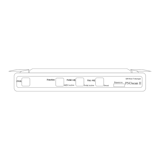
Page 25: Tusb Interface Front Panel
Standard MIDI input connection. Normally not connected. Used in more complex setups when communication to diagnostic programs such as the MIDI9 alignment program is needed. Connect a host computer to this port for convenient use of the PNOscan II system and computer software. USB 2.0 compliant Serial I/O Used with PNOscan Version 45, modified for use with the QRS sound Module. -
Page 26: Connection Diagrams [Grand & Upright]
Optional AC Power Adapter [7921701] 38” 10-pin [7921706] Not required when TUSB is connected to a computer via the USB 2.0 socket. DO NOT CONNECT ON V45 TUSB VERSIONS. QRS Music Technologies, Inc. / Technical Support - 800-247-6557 / www.qrsmusic.com... -
Page 27: Troubleshooting
The Key Adj light is flashes steadily. The system is in Mute Mode The PWR light is red Indicates a USB failure - Call your dealer or QRS Technical Support QRS Music Technologies, Inc. / Technical Support - 800-247-6557 / www.qrsmusic.com... -
Page 28: Warranty
(the “Shorter Warranty Period”) which is two years from the date that your dealer purchased the Product from QRS. If you cannot provide a proof of purchase date, you may contact us in the manner described below and we will assist you in determining the date that your dealer purchased the Product from us and determining the Shorter Warranty Period. -
Page 29: Warranty
1) Retain your proof of purchase and purchase date and send in your Warranty Registration Card 2) Notify QRS or any authorized dealer of any warranty claim within ten (10) days after discovery and provide a detailed explanation of the problem. - Page 32 QRS Music Technologies, Inc. 2011 Seward Ave. Naples, FL 34109 239-597-5888 239-597-3936 Fax Copyright © 2006 QRS Music Technologies, Inc. All rights reserved...
Need help?
Do you have a question about the PNOscan II and is the answer not in the manual?
Questions and answers