Table of Contents
Advertisement
Advertisement
Table of Contents

Summary of Contents for Topcon TRC-50DX
- Page 1 INSTRUCTION MANUAL RETINAL CAMERA TRC-50DX...
-
Page 3: Introduction
Disposal When disposing of TRC-50DX parts, follow the local regulations for disposal and recycling. "Because prolonged intense light exposure can damage the retina, the use of the device for ocular examination should not be unnecessarily prolonged, and the brightness setting should not exceed what is needed to provide clear visualization of the target structures. -
Page 4: Environmental Conditions For Use
(4) Do not store the instrument where chemicals are stored or gas is generated. 3. Normal life span of the instrument: 8 years from delivery providing regular maintenance is performed [TOPCON data] ENVIRONMENTAL CONDITIONS FOR PACKAGING IN TRANSPORTATION Temperature: -20°C ~ 50°C... -
Page 5: Display For Safe Use
DISPLAY FOR SAFE USE To encourage safe and proper use and to prevent injuries to the operator and others or potential damage to property, important messages are put on the instrument body and inserted in the instruction manual. We suggest that everyone understand the meaning of the following displays, icons and text before reading the "SAFETY CAUTIONS"... -
Page 6: Safety Cautions
SAFETY CAUTIONS WARNINGS Icon Prevention item Page To avoid fire and electric shock in case of leakage, be sure to use a grounded receptacle. Do not connect to receptacles that are not grounded. To avoid electric shock, do not attempt disassembling, rebuilding and/or repairs on your own. - Page 7 CAUTIONS Icon Prevention item Page To prevent damage and injuries, do not install the instrument on an uneven, unsteady or sloped surface. To avoid electric shock, do not handle the plugs with wet fingers. To avoid discomfort or damage to the patient's eye, do not brighten the illumination lamp more than necessary.
- Page 8 CAUTIONS Icon Prevention item Page To prevent falls and injury during transportation of the instrument, be sure to lock the base and arm by using the locking levers. This ----- will prevent the instrument from moving and sliding. To avoid injury during carrying, be sure to hold the instrument body at the bottom with two people.
-
Page 9: Usage And Maintenance
USAGE AND MAINTENANCE USAGE • The TRC-50DX Retinal Camera is an electric instrument for medical use. Use this instrument under a doctor's guidance. USER MAINTENANCE To ensure the safety and performance of the instrument, all maintenance work, unless specified in this manual, shall be conducted by trained service engineers. -
Page 10: Warning Displays And Positions
To ensure safety, this machine provides warning displays. Use the instrument correctly by observing the display instructions. If any of the following display labels are missing, contact your TOPCON dealer at the address listed on the back cover of this manual. CAUTION... -
Page 11: Table Of Contents
CONTENTS INTRODUCTION ........................1 CAUTIONS FOR USE ......................1 ENVIRONMENTAL CONDITIONS FOR USE..............2 STORAGE, USAGE PERIOD AND OTHERS..............2 ENVIRONMENTAL CONDITIONS FOR PACKAGING IN TRANSPORTATION....2 CHECKPOINTS FOR MAINTENANCE ................2 DISPLAY FOR SAFE USE....................3 SAFETY CAUTIONS ......................4 USAGE AND MAINTENANCE....................7 USAGE ..........................7 USER MAINTENANCE....................... - Page 12 OBJECTIVE OPERATIONS PHOTOGRAPHY BY INCLINATION AND SWINGING.............42 BLUE FILTER PHOTOGRAPHY..................43 PHOTOGRAPHY WITH ALTERNATIVE FILTER (EXCLUDING TYPE IA).......43 STEREO PHOTOGRAPHY ....................44 INTERNAL FIXATION TARGET MOUNT (ONLY IN TYPE IA) .........45 BEFORE REQUESTING SERVICE TROUBLESHOOTING......................46 ERROR CODE LIST ......................49 SPECIFICATIONS AND PERFORMANCE SPECIFICATIONS ......................50 ELECTRIC RATING ......................50 SYSTEM CLASSIFICATION.....................51...
- Page 13 REFERENCE MATERIAL SHAPE OF PLUG ......................71 SYMBOL ...........................71 USABLE AUTOMATIC INSTRUMENT TABLE ..............72 ELECTROMAGNETIC COMPATIBILITY ................73 RELATION BETWEEN SETTING OF ILLUMINATION/FLASH LEVEL AND MAXIMUM RADIANCE ....................77 INFORMATION ABOUT THE OPTICAL RADIATION HAZARD FOR THE USER ........................78...
-
Page 14: Nomenclature
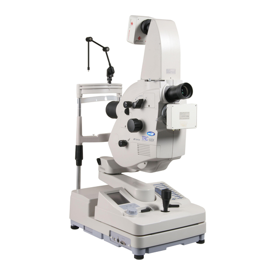
NOMENCLATURE COMPONENTS OF MAIN UNIT Main unit UPPER mount UPPER mount locking lever Astigmatic correction knob Diopter compensation lens selector External Cover Shading compensation cover Objective lens barrel Optical finder LOWER mount Objective lens LOWER mount locking lever Cable holder Angle changing lever Focusing knob Internal fixation target mount... - Page 15 "Horizontal" index window Tilting unit Inclination handle Inclination rail Inclination brake knob 2nd arm Base unit Control panel 1st arm Photography switch Base Illumination level knob Main unit connecting cord Control lever Cover Level adjuster Base unit connecting cord Power cord Fuse holder Power switch External connection terminal...
-
Page 16: Composition Of Parts Which Contact With The Human Body
External fixation target Chinrest unit Forehead rest Canthus marker Headband Chinrest tissue pin Chinrest Chinrest adjusting knob Column Headband....Used when fixing the patient's head. (Only in relevant products) COMPOSITION OF PARTS WHICH CONTACT THE HUMAN BODY Forehead rest : Polyamide resin Chinrest : Polyamide resin Headband... -
Page 17: Components Of Base Unit
COMPONENTS OF BASE UNIT UPPER/LOWER selector switch Flash correction switches Flash selector panel Control panel Flash selector switch TIME (Timer) switch Ba (Barrier) switch Ex (exciter) switch SPLIT switch SPLIT TIME Operation panel STEREO STEREO LOCK LOCK FREE FREE FREE FREE Illumination level knob STEREO lever... -
Page 18: Components On Control Panel Screen
COMPONENTS ON CONTROL PANEL SCREEN Setting operation display (Example of the photography mode color) ALIGNMENT switch SMALL PUPIL switch FILTER switch Photography mode indication Menu switch Timer indication Angle of coverage indication FLASH (flash level) indication APERTURE (photography aperture) Right/left detection indication indication Illumination level... - Page 19 SET MENU display Carries out a variety of settings. Press the MENU button on the setting operation display, and "SET MENU" will be displayed. Refer to "SETTING ON THE SET MENU DISPLAY" on page 23. FLASH LEVEL (Flash level standard setting) FIX COLOR (External fixation color selection) FLICK (External fixation blinking selection) FILTER IN/OUT (Filter link operation method)
-
Page 20: Names In Optical Finder
NAMES IN OPTICAL FINDER Reticles Alignment bright spot Split lines "With split" type Reticles TIMER Alignment bright spot "Without split" type NOMENCLATURE... -
Page 21: Standard Accessories
STANDARD ACCESSORIES Upon unpacking, make sure that all the following standard accessories are included. Numbers in ( ) are the quantities. Spare parts case (1) Fuse (2) Chinrest tissue paper (1) Chinrest tissue pin (2) External fixation target (1) Allen wrench (2) Large: (2.5) Small (1.5) Dust cover (1) -
Page 22: Setup
SETUP CONNECTING THE POWER CORD To avoid fire and electric shock in case of leakage, be sure to use a WARNING grounded receptacle. Do not connect to receptacles that are not grounded. CAUTION To avoid electric shock, do not handle the plugs with wet fingers. Make sure that the on the instrument is in the "OFF"... -
Page 23: Connecting The External Device
CONNECTING THE EXTERNAL DEVICE Consult your dealer for connection with external devices. Use the external device complying with IEC 60950. Connecting to IMAGEnet This instrument can be connected to IMAGEnet (optional accessory) by two methods. Connecting method 1: when using the USB terminal Connect one end of the USB cable (optional accessory) to the USB terminal. -
Page 24: Reset From Power Save State
RESET FROM POWER SAVE STATE This instrument has a power saving feature to save energy. After 30 minutes of non-use, the instrument switches to power save mode. In ICG fluorescein photography (only in Type IA), after 60 minutes of non-use, the instrument switches to power save mode. -
Page 25: Setting On The Set Menu Display
SETTING ON THE SET MENU DISPLAY Setting for the following items can be done on the "SET MENU" display on the control panel: "FLASH LEVEL" (flash level standard setting), "FIX COLOR" (external fixation color selection), "FLICK" (external fixation blinking selection) and "FILTER IN/OUT" (filter link operation method). - Page 26 FLASH LEVEL (Flash level standard setting) You can set the flash level standard value for each photography mode. The following table shows the data of the factory default. Press the on the "SET MENU" display. FLASH LEVEL The "FLASH LEVEL" setting display appears. Touch the value indication window to be changed in each photography mode.
- Page 27 FIX COLOR (External fixation color selection) You can select "AUTO" (automatic) or "GREEN" or "RED" for the external fixation lamp. "AUTO" is the factory default. Press the on the "SET MENU" display. FIX COLOR The "FIX COLOR AUTO/GREEN/RED" selection display will appear.
- Page 28 FILTER IN/OUT Decide the Ba (barrier) filter or Ex (exciter) filter link operation method. "OUT" is the factory default. Press the switch on the "SET MENU" display. FILTER IN/OUT The "FILTER IN/OUT" selection display will appear. Press and select . (Refer to the table below.) Press the switch, to store the data.
- Page 29 Set the interface to "USB" or "NORMAL". "NORMAL" is the factory default. Press the switch on the "SET MENU" display. The "USB/NORMAL" selection display will appear. Press and select "USB" or "NORMAL". Press the switch, to store the data. The "SET MEMORIZE MENU"...
-
Page 30: Basic Operations
BASIC OPERATIONS PREPARATION FOR PHOTOGRAPHY Check the connection of the power cord. Refer to "CONNECTING THE POWER CORD" on page 20 for the connection procedure. Set each POWER SWITCH on the instrument and the external record device to the "ON" (I) position. - Page 31 How to move the instrument by the control lever. • To move the base unit slightly back and forth or right and left, tilt the control lever in the proper direction. Operation of control lever (back and forth/right and left) Guiding the base cover with one hand, push the control lever with the other hand in the desired direction.
-
Page 32: Preparation Of The Patient
PREPARATION OF THE PATIENT To avoid injury while moving the chinrest up and down, instruct the CAUTION patient to keep hands away from moving parts. Be careful not to let the patient hold the column. His/her finger may CAUTION be pinched between the column and 1st/2nd arm causing injury. NOTE Ask the patient to remove any glasses or contact lenses. - Page 33 Adjust the chinrest height by turning the chinrest adjusting knob so that the outside corner of the patient's eye is level with the Canthus marker on the chinrest column. Then, let the patient rest his/her forehead on the forehead rest. Use the headband if necessary. (The headband is installed only in the relevant products.) Canthus marker Guide the patient's eye so that the target part of the fundus can be photographed.
-
Page 34: Color Photography
COLOR PHOTOGRAPHY To avoid discomfort or damage to the patient's eye, do not brighten CAUTION the illumination lamp more than necessary. To avoid discomfort or damage to the patient's eye, do not make a CAUTION flash intensity level higher than necessary. To avoid injury while moving the base, do not place your fingers into CAUTION the gap between the instrument base and the power supply unit. - Page 35 The flash level is automatically changed according to photography modes. Set the flash level. Set flash level with the and the FLASH SELECTOR SWITCH FLASH CORRECTION SWITCH Flash correction switch Flash selector switch Tell the patient to watch the external fixation target or the inter- nal fixation target (only in Type IA).
- Page 36 Push the base unit toward the patient side slowly, and the retinal image is seen in the opti- cal finder. Watching the observed image in the optical finder, adjust its brightness with the ILLUMINATION LEVEL KNOB Finely adjust the main body forward and backward to illuminate the retina evenly. •...
- Page 37 If you cannot align the split lines into one line by operating the focusing knob, change the diopter compensation lens by the diopter compensation lens selector. If the split lines are not easily visible, lower the illumination level. If one of the split lines cannot be seen, check if dilation is sufficient or if the eye is obstructed by eyelashes or the eyelid, interrupting the light.
- Page 38 Make sure that the split line is aligned with the alignment bright spot. Press the when the patient's eye is fully open. Instruct him/her not to blink. PHOTOGRAPHY SWITCH Photography switch If the light intensity of the photography image is not correct, adjust it with the and repeat the alignment and photography procedure.
-
Page 39: Fag Photography
FAG PHOTOGRAPHY To avoid fire and electric shock, do not put cups or other containers WARNING with liquids near the instrument. To ensure correct imaging, adjust the height of the automatic instru- NOTE ment table so that the patient can relax with his/her chin placed cen- trally on the chinrest. - Page 40 Make the same adjustments, as 3~10 for "COLOR PHOTOGRAPHY", and focus the reti- nal image properly. Prepare for the intravenous injection of fluorescein. How to take distinct fluorescein photographs: If too much time is taken in giving the intravenous injection, the fluorescein will be dif- fused in the blood vessels and diagnostic quality photographs will not be possible.
-
Page 41: Icg Fluorescein Photography (Only In Type Ia)
ICG FLUORESCEIN PHOTOGRAPHY (ONLY IN TYPE IA) To avoid fire and electric shock, do not put cups or other containers WARNING with liquids near the instrument. To ensure correct imaging, adjust the height of the automatic instru- NOTE ment table so that the patient can relax with his/her chin placed cen- trally on the chinrest. -
Page 42: Red Free Photography With Green Filter (Only In Relevant Products)
RED FREE PHOTOGRAPHY WITH GREEN FILTER (ONLY IN RELEVANT PRODUCTS) To avoid fire and electric shock, do not put cups or other containers WARNING with liquids near the instrument. To ensure correct imaging, adjust the height of the automatic instru- NOTE ment table so that the patient can relax with his/her chin placed cen- trally on the chinrest. - Page 43 Press the PHOTOGRAPHY SWITCH Photography switch When you keep pressing the , it is possible to take one (1) pic- PHOTOGRAPHY SWITCH ture per second. BASIC OPERATIONS...
-
Page 44: Objective Operations
OBJECTIVE OPERATIONS PHOTOGRAPHY BY INCLINATION AND SWINGING To prevent the instrument from malfunctioning, do not perform inclina- NOTE tion and base swinging (right and left) while holding the camera con- nected to UPPER or LOWER mount. When performing inclination, loosen the gradually until you can INCLINATION BRAKE KNOB move the... -
Page 45: Blue Filter Photography
BLUE FILTER PHOTOGRAPHY To ensure correct imaging, adjust the height of the automatic instru- NOTE ment table so that the patient can relax with his/her chin placed cen- trally on the chinrest. The basic operation is the same as "COLOR PHOTOGRAPHY". It is possible to photograph with the EXCITER filer as the blue filter by setting the to "OFF". -
Page 46: Stereo Photography
STEREO PHOTOGRAPHY Allow the illumination light to come into the patient's pupil so that uniform brightness can be kept on the eye. Then, take a picture using the . The basic operation is the STEREO LEVER same as "COLOR PHOTOGRAPHY". Align the patient's pupil and the instrument in proper positions. -
Page 47: Internal Fixation Target Mount (Only In Type Ia)
INTERNAL FIXATION TARGET MOUNT (ONLY IN TYPE IA) Internal fixation target mount (in "With split" type of Type IA) Look into the optical finder and focus the retinal image. Turn off the SPLIT SWITCH * If the is turned on, the knob will be SPLIT SWITCH SPLIT TIME... -
Page 48: Before Requesting Service
When an error is found, review the Check List below. If, after following the instructions below, you still have problems or if the problem does not fall into any of the categories below, contact your dealer or TOPCON (see the back cover). Check List... - Page 49 Problem Condition Check Page Split lines cannot be seen. • SPLIT switch is set to OFF. Turn SPLIT line ON with Split switch. • Diopter compensation lens selector is Return Diopter compensation lens selec- not set to "0". tor to "0". •...
- Page 50 Problem Condition Check Page Operator cannot see the • Illumination light is not ON. Adjust the illumination level. patient's eye. • The objective lens cap is set. Remove the objective lens cap. • BARRIER filter and EXCITER filter are Set BARRIER filter and EXCITER filter to set to "IN".
-
Page 51: Error Code List
ERROR CODE LIST When "Err " ( means an error number) is displayed in the blinking status on the con- trol panel screen with a beep sound due to an operation error or a malfunction of the instru- ment, correct the error according to the table below. Display Cause How to correct... -
Page 52: Specifications And Performance
SPECIFICATIONS AND PERFORMANCE SPECIFICATIONS • Resolving power of the fundus camera angle part radial tangential (Examined eyes 0D, on 35mm film surface) center 50° middle (r/2) periphery (r) center 35° middle (r/2) periphery (r) center 20° middle (r/2) periphery (r) unit : lp/mm •... -
Page 53: System Classification
LEAKAGE CURRENT. • Degree of protection against harmful ingress of water: IPx0 The TRC-50DX has no protection against ingress of water. (The degree of protection against harmful ingress of water defined in IEC 60529 is IPx0.) • Classification according to the method(s) of sterilization or disinfection recommended by the manufacturer: not applicable. -
Page 54: Operation Principle
OPERATION PRINCIPLE The observation light emitted from the illumination optical system illuminates the patient's eye (the eye to be photographed), and the image formed by the observation/photography optical systems is observed. By operating the photography switch on the instrument, the photography light is emitted from the illumination optical system to illuminate the patient's eye. -
Page 55: Maintenance
• When not in use, always turn the OFF. POWER SWITCH ORDERING CONSUMABLES • When ordering consumables and spare parts, contact your dealer or TOPCON (see the back cover) and tell them the article name, article code and quantity. Article name Article code... -
Page 56: Replacing The Illumination Lamp
REPLACING THE ILLUMINATION LAMP To avoid electric shock, be sure to turn the power switch off and CAUTION unplug the power cord before replacing the lamp. To avoid burns, do not replace the lamp with a new one immediately CAUTION after it goes off. -
Page 57: Replacing The Xenon Lamp
Insert the new illumination lamp straight and tighten securely the two fixing screws of the illumination lamp. Attach the lamp house cover by matching the projection at the bottom part of the lamp house cover with the groove of the body cover. If the lamp house cover is left unfixed, an error is displayed on the control panel and operations, including photography, cannot be done. - Page 58 Slowly pull the xenon lamp straight out. Insert the new xenon lamp straight in the receptacle until it reaches the end. Tighten the xenon lamp set screw fully with a coin clockwise. Attach the lamp house cover by matching the projection at the bottom part of the lamp house cover with the groove of the body cover.
-
Page 59: Replacing The Fuse
REPLACING THE FUSE To avoid electric shock when replacing the fuse, be sure to unplug the WARNING instrument before removing the fuse cover. Do not use ungrounded outlets. Do not plug in the instrument without the fuse cover. To avoid fire in the event of an instrument malfunction, use only the WARNING fuses that are marked with the label at the side of the fuse holder. -
Page 60: Refilling The Chinrest Tissue Paper
REFILLING THE CHINREST TISSUE PAPER • When the chinrest tissue paper is used up, pull out the chinrest tissue pins and refill the tis- sue paper. Chinrest tissue pin(s) THE FAG FLUORESCEIN FILTER To avoid electric shock, be sure to turn the power switch off and CAUTION unplug the power cord before replacing the filter. - Page 61 Install the filter into the filter frame. It is not necessary to distinguish between the front and rear of the filter. After installing the filter into the filter frame, apply the adhesive to the outer circumfer- ence of the filter. Consult your dealer for the adhesive. Insert the filter firmly.
-
Page 62: Cleaning
CLEANING • Before using this instrument, always clean it. CLEANING THE EXTERNAL COVER, CONTROL PANEL AND OTHERS • To prevent the plastic parts of the instrument body from discoloring NOTE and deteriorating, do not use volatile solvents for cleaning, including benzine, thinner, ether, gasoline, etc. -
Page 63: Cleaning The Lens Which Is Seen In Upper Mount
Don't let any strong-alkaline liquid adhere to the objective lens. If such liquid adheres to the lens, immediately wipe it off. If it is difficult to remove a stain from the objective lens, contact your dealer or TOPCON (see the back cover). -
Page 64: Optional Accessories
OPTIONAL ACCESSORIES The optional accessories for TRC-50DX enable a variety of photography. Ensure that the 35mm camera is installed firmly by fastening the 35mm camera body locking lever. CAUTION If installed loosely, the camera may fall off, resulting in severe damage to the unit and bodily injury. -
Page 65: Optional Accessory Mounting/Detaching Methods
OPTIONAL ACCESSORY MOUNTING/DETACHING METHODS How to install/remove the 1× relay lens adapter/video relay lens adapter Mounting method Lock the base fixing lever and the inclination brake knob. Turn the UPPER mount locking lever to remove the cap. Remove the cap from the optional accessory and install it onto the instrument body. Stand next to the instrument body and install the optional accessory straight from above with both hands. - Page 66 Installing/removing the AUTO FLUO filter attachment To avoid electric shock, be sure to turn the power switch off and CAUTION unplug the power cord before replacing the filter. To avoid burns due to the hot filter unit, do not replace the filter with a CAUTION new one immediately after the power goes off.
- Page 67 How to install the AUTO FLUO Ba filter Turn the OFF ( ) and unplug the power cord. POWER SWITCH Remove the barrier filter cover screw. Then, remove the barrier filter cover. Turn the turret by fingers. Hold the filter frame showing "F" with your fingers or radio pliers and pull it out straight.
- Page 68 How to install the internal fixation target mount (for "without split" type) • Nomenclature Knob Fixation point Protective cap Fixation target Locking cap • How to attach the Internal Fixation Target (1) Take off the cover of the internal fixation target mount on the main body of retinal camera.
-
Page 69: Accessory Lens Cleaning Methods
ACCESSORY LENS CLEANING METHODS Dust or other impurities adhering to the lens, which is seen in the mount, may be reflected in the retinal images photographed. In the presence of such impurities, the lens must be cleaned according to the methods specified below. Cleaning the outer side of the lens: Blow off dust or other impurities with a hand blower. -
Page 70: Relay Lens Adapter Or-2
1× RELAY LENS ADAPTER OR-2 35mm camera body locking lever Fixing ring 35mm camera mount Mount Mount cap Connector Photography method Set the to "UPPER" on the control panel. UPPER/LOWER SELECTOR SWITCH Perform alignment and photography for retina in the same procedure as "COLOR PHO- TOGRAPHY"... -
Page 71: Tv Relay Lens Adapter
TV RELAY LENS ADAPTER • Precautions and suggestions to use Be careful not to use an improper video camera. Mount Mount Video camera mount Connector • How to attach the video camera See the instruction manual for video camera. • Cable connection Insert the cable into the cable holder on the main body. - Page 72 • How to take a picture Set the to "UPPER" on UPPER/LOWER SELECTOR SWITCH the control panel. Perform alignment and photography for retina in the same procedure as "COLOR PHOTOGRAPHY", "FAG LOCK LOCK PHOTOGRAPNY" or "ICG FLUORESCEIN PHOTOG- FREE FREE RAPHY".
-
Page 73: Reference Material
REFERENCE MATERIAL SHAPE OF PLUG Country Voltage/frequency Shape of plug Mexico 110V/50Hz Type C&E Argentina 220V/60Hz Type A Peru 220V/60Hz Type A Venezuela 110V/50Hz Type C&E Bolivia & Paraguay Type A (Most common) 220V/60Hz Type H (Infrequently) Chile 220V/60Hz Type A Colombia 110V/50Hz Type C... -
Page 74: Usable Automatic Instrument Table
USABLE AUTOMATIC INSTRUMENT TABLE Automatic instrument table AIT-15S Because the instrument height can be adjusted to the desired position, you can take a picture more easily. Specifications • Dimensions ....510(W) × 490(D) mm • Table height....600 ~ 820mm • Table size .....490 × 500mm •... -
Page 75: Electromagnetic Compatibility
Guidance and manufacturer's declaration - electromagnetic emissions The TRC-50DX is intended for use in the electromagnetic environment specified below. The customer or the user of the TRC-50DX should assure that it is used in such an environ- ment. Emissions test... - Page 76 Guidance and manufacturer's declaration - electromagnetic immunity The TRC-50DX is intended for use in the electromagnetic environment specified below. The customer or the user of the TRC-50DX should assure that it is used in such an environ- ment. IEC 60601...
- Page 77 Guidance and manufacturer's declaration - electromagnetic immunity The TRC-50DX is intended for use in the electromagnetic environment specified below. The customer or the user of the TRC-50DX should assure that it is used in such an environ- ment. Immunity test...
- Page 78 Recommended separation distance between portable and mobile RF communications equipment and the TRC-50DX The TRC-50DX is intended for use in an electromagnetic environment in which radiated RF dis- turbances are controlled. The customer or the user of the TRC-50DX can help prevent electro-...
-
Page 79: Relation Between Setting Of Illumination/Flash Level And Maximum Radiance
RELATION BETWEEN SETTING OF ILLUMINATION/ FLASH LEVEL AND MAXIMUM RADIANCE When the maximum radiance is "1", the ratio of radiance is shown below in setting of illumination/ flash level. Illumination level (Observation light) Flash level (Photographing light) Indicated set Indicated set Level ratio Level ratio value... -
Page 80: Information About The Optical Radiation Hazard For The User
(aphakes) and has not been replaced by a UV-blocking lens or for eyes of very young children. • The value stated for TRC-50DX gives a measurement of hazard potential when the instrument is operated at maximum intensity and maximum aperture. Values of L... - Page 81 Please inform us of the date of purchase. • Defective condition: Please provide us with as much detail as possible on the problem. RETINAL CAMERA TRC-50DX INSTRUCTION MANUAL 2006 version (2006.07-50TH Date of issue: Aug. 1st, 2006 Published by TOPCON CORPORATION 75-1 Hasunuma-cho, Itabashi-ku, Tokyo, 174-8580 Japan.
- Page 82 (European Sole Sales Company) Essebaan 11, 2908 LJ Capelle a/d IJssel,THE NETHERLANDS Phone:010-4585077 Fax:010-2844940 www.topcon.eu ITALY OFFICE:Via Dell' Industria n.60, 20037 Paderno Dugnano, (Milano), ITALY Phone:02-61-25-583 E-mail:info.topconitaly@tiscali.it www.topcon.it TOPCON DEUTSCHLAND G.m.b.H. Giesserallee 31-33 D-47877 Willich GERMANY Phone:02154-8850 Fax:02154-885111 www.topcon.de Med@topcon.de TOPCON ESPAÑA S.A.
Need help?
Do you have a question about the TRC-50DX and is the answer not in the manual?
Questions and answers