Table of Contents
Advertisement
Quick Links
Advertisement
Table of Contents

Subscribe to Our Youtube Channel
Related Manuals for Apex Digital DBG-8


Summary of Contents for Apex Digital DBG-8
- Page 3 APEX Schoebroekstraat 62 3583 Beringen (Paal) BELGIUM Tel: + 32 (0)11 28 61 91 Fax: + 32 (0)11 25 56 38 email: info@apex-audio.be website: www.apex-audio.be...
-
Page 4: Environmental Precaution
Environmental precaution EU Directive 2002/96/EC Remark: This notice applies only to countries within the European Union (EU) and Norway Electrical and electronic equipment may contain hazardous substances for humans and their environment. The “crossed out wheelie bin” symbol present on the device and represen- ted above is there to remind one of the obligation of selective collection of waste. - Page 5 However if you would like to make the best use of the dBG-8 or would like to know more about nois-gates in general, we invite you to read this manual.
- Page 6 User-serviceable parts There are no user serviceable parts inside the dBG-8. In case of failure, refer all servicing to the factory. Servicing is required when the dBG-8 has been damaged in any way, such as when a power supply cord or plug is...
-
Page 7: Attack Time
On the dBG-8, the hold time is fixed and can not be altered by the user. If really necessary, the hold time can be adjusted by a trim control on the circuit board of the dBG-8. -
Page 8: Product Highlights
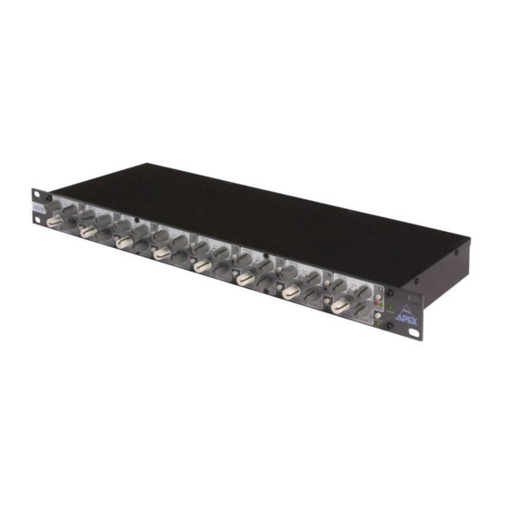
PRODUCT HIGHLIGHTS The dBG-8 offers 8 individual gates in an extremely compact package. The user controls are extre- mely straightforward and intuitive. Connections are balanced on TRS- Jacks. The dB8 offers profes- sional sound quality with user friendly controls in a compact housing. -
Page 9: Front And Rear Panel Description
FRONT AND REAR PANEL DESCRIPTION All 8 channels being equal, only one channel is described. FRONT PANEL 1: THRESHOLD: variable between -60 dBu and +15dBu. When the input level reaches the level set by this control the gate will open and let the sound pass. When the sound level at the input stays under the threshold, the gate will stay close. -
Page 10: Rear Panel
REAR PANEL 1. POWER INLET: please connect the supplied power chord to this inlet. The power supply of the dBG-8 is auto-sensing and accepts between 100V and 230V (50-60Hz). Do never connect a broken or damaged power chord or when not sure what the voltage is. -
Page 11: Cable Connections
RING of the connector. The ground of both signals is shared on the SLEEVE of the con- nector. Connect the Send signal to the Input of the dBG-8 and the Output of the dBG-8 to the Return signal. TIP: when by accident you exchange the in- and out-put connections on the dBG-8 the gate will not function. - Page 12 When you have a balanced insert point or are inserting the gate in a balanced line, connect the output or send signal of the console or line to the input of the dBG-8, and connect the output of the gate to the Return or input connection of the console or line.
- Page 13 In this chapter we will briefly try to explain why the gate was invented and how it is used. But whatever we are telling you, please feel free to experiment and make creative use of the dBG-8 (just remember that all tricks explained in this manual are normally done by trained professionals).
- Page 14 Apex dBG-8 to clean up your sound. Using the gate in a right way, we can try to minimize the effects of phase shift.
- Page 15 Apex dBG-8’s, you know you are in deep trouble since all the audience will ask to get it louder and that dreadful feedback monster is smiling in your face.
-
Page 16: Parameter Setting
What is the effect of the different parameters and how to correctly set a gate? Not all parameters on the dBG-8 are accessible to the user. To be able to fit 8 channels in 1 Rack Unit Height some of them are fixed and can not be altered. We will however describe them all to give you a better understanding. - Page 17 The value of the attack time of the dBG-8 was chosen after hours of experimenting so that the final value chosen would suit almost all real-live applications.
- Page 18 Raising the threshold is not a solution since you might cut out some snare drum hits. First of all: Using the EQ on the dBG-8 will not alter the sound of the signal!!! Unless you activate the ‘Listen’ switch.
- Page 19 It sounds much more complex than it is to do this: make the drummer play, activate the EQ on the snare drum channel of the dBG-8 and activate the listen button. You will now hear the effect of the EQ on the side chain channel.
-
Page 20: Technical Specifications
Technical Specifications Line Inputs: Eight balanced high impedance line level inputs, 10 kOhms, on 1/4’ TRS jack connector Maximum Input Level: +20 dBu Line Outputs: Eight electronically balanced low impedance outputs, < 600 Ohms Maximum Output Level: +20 dBu into 600 Ohms Output noise: <...
Need help?
Do you have a question about the DBG-8 and is the answer not in the manual?
Questions and answers