Table of Contents
Advertisement
Quick Links
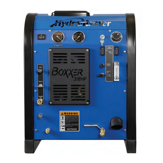
Boxxer 318HP
Owner's Manual
HydraMaster
th
11015 47
Avenue West
Mukilteo, Washington 98275
MAN-46477 Rev. A, February 13, 2015
(P/N 000-182-735)
No part of this manual may be reproduced or used in any form or by any means (i.e. graphic, electronic, photocopying or electronic
retrieval systems) without the express written permission of HydraMaster. Specifications and information in this document are
subject to change without prior notice. All rights reserved. © 2015 HydraMaster
Advertisement
Table of Contents

Subscribe to Our Youtube Channel
Summary of Contents for HydraMaster Boxxer 318HP
- Page 1 No part of this manual may be reproduced or used in any form or by any means (i.e. graphic, electronic, photocopying or electronic retrieval systems) without the express written permission of HydraMaster. Specifications and information in this document are subject to change without prior notice. All rights reserved. © 2015 HydraMaster...
-
Page 3: Table Of Contents
Machine Specifications ..............1-10 High Altitude Operation ..............1-12 Local Water Precautions ..............1-12 INSTALLATION INFORMATION ..............SECTION 2 Operating the Boxxer 318HP In Hot Weather ........2-2 Setting Up the Boxxer 318HP ............2-5 CLEANING INFORMATION ................. SECTION 3 Precautions ..................3-1 Preparing the Carpet for Extraction ........... - Page 4 Exhaust Assembly Parts List ............. 9-33 65 Gallon Universal Recovery Tank (URT) Assembly Parts List ..9-35 Dura-Flow Automatic Pump Out (APO) Assembly Parts List ..... 9-37 Dura-Flow APO Pump Assembly Parts List ........9-38 Hose Routings ................... 9-39 Boxxer 318HP Owner’s Manual: ii...
- Page 5 Recovery Tank .................. 11-1 Chemical System ................11-1 Control Panel ..................11-1 Cleaning Tool ..................11-2 Water Heating System ............... 11-2 Hard Water Deposits ................. 11-2 Warranty Procedure ................11-2 HydraMaster Limited Warranty ............11-3 iii: Boxxer 318HP Owner’s Manual...
- Page 6 Figure 2-3. Install Fuel Pump, Outlet Side Up ............2-6 Figure 2-4. Fuel Pump Must Be in Vertical Position ........... 2-6 Figure 4-1. Boxxer 318HP Dash Assembly - View 1 of 2 ........... 4-1 Figure 4-2. Boxxer 318HP Dash Assembly - View 2 of 2 ........... 4-2 Figure 4-3.
- Page 7 Figure 9-25. Idler Pulley Assembly ................9-32 Figure 9-26. Exhaust Assembly ................9-33 Figure 9-27. 65 Gallon Universal Recovery Tank (URT) Assembly ......9-34 Figure 9-28. Dura-Flow APO Assembly ..............9-36 Figure 9-29. Dura-Flow APO Pump Assembly ............9-38 v: Boxxer 318HP Owner’s Manual...
- Page 8 Boxxer 318HP Owner’s Manual: vi...
- Page 9 1- General Information The Boxxer 318HP is a carefully engineered truckmount designed and manufactured by HydraMaster for hard surface cleaning as well as carpet and upholstery cleaning. The Boxxer 318HP can also be used for high pressure washing applications. The system utilizes an internal combustion engine to provide the power necessary to turn both a blower (also referred to as a vacuum pump) and a high pressure water pump.
-
Page 10: General Information
If you have any questions regarding the operation, maintenance or repair of this machine, please contact your local distributor. If your question cannot be resolved by your distributor or by the information within this manual, you may contact HydraMaster direct using the following phone numbers. HOURS TELEPHONE NUMBERS... -
Page 11: Warnings, Cautions And Notices
WARNINGS, CAUTIONS AND NOTICES HydraMaster uses this WARNING symbol throughout the manual to warn of possible injury or death. This CAUTION symbol is used to warn of possible equipment damage. This NOTICE symbol indicates that federal or state regulatory laws may apply, and also emphasizes supplemental information. - Page 12 Transporting a vented fuel container that presently contains, or has ever contained in the past, a flammable liquid is strictly forbidden by HydraMaster and by federal and state regulations. Doing so will increase the risk of fire and explosion. Serious injury or death may result.
- Page 13 Never smoke in or around the truckmount. Doing so will increase the risk of fire and explosion. Serious injury or death may result. During the operation of the truckmount the exhaust system will become extremely hot. Keep all flammable materials away from the truckmount exhaust system. Failure to do so will increase the risk of fire and explosion.
- Page 14 Never allow water to freeze inside the truckmount. Serious component damage will occur. Perform all freeze guarding procedures outlined in this digital Owner’s Manual. Many vehicles have critical components mounted directly below the floor that can easily be damaged. Before drilling holes in the floor of the vehicle, inspect the underside of the vehicle for critical components.
-
Page 15: Responsibilities
RESPONSIBILITIES The Purchaser’s Responsibilities Prior to purchasing a van, ensure that the payload is suitable for all of the equipment that will be installed and transported. This includes and is not limited to: the truckmount, recovery tanks, fresh water tanks and any other on-board water, hose reels, hoses, cleaning tools, chemicals, drying equipment, etc. - Page 16 • Ensure proper connection of the fuel lines. • Ensure proper connection and installation of the battery. Verify that the battery is in accordance with HydraMaster’s recommendation. • Check the pump, vacuum blower and engine oil levels prior to starting the truckmount.
- Page 17 Training The distributor should provide a thorough review of the operation manual with the purchaser along with instruction and familiarization in: • How all the truckmount’s systems function. • All safety precautions and their importance. • How to correctly start and shut down the truckmount. •...
-
Page 18: Machine Specifications
MACHINE SPECIFICATIONS Frame Dimensions 24.0" W x 31” H x 36" D Weight 570 lbs. Engine- Briggs and Oil Type Synthetic 5W-30 Stratton Vanguard 18 HP Capacity Approx. 1 1/2 quarts (48 oz.) when changing oil and filter Engine rpm 3,150 rpm Fuel Consumption 1.0 gph... - Page 19 Standard Equipment Recovery Tank 65 Gallon Cleaning Tool RX-15 Rotary Hard Surface Cleaning Tool Hoses 2” x 50 ft Blue Vacuum Hose 1 1/2” x 10 ft Blue Whip Hose 1 1/2” Blue Dump Hose 1/4” x 100 ft Blue Solution Hose Chemical Jug 5 gallon...
-
Page 20: High Altitude Operation
Hard Water Advisory HydraMaster recognizes that any hard water deposits which might occur within the water system of our truckmounts is a serious problem. The precision technology of truckmount heat exchanger systems is intolerant of any foreign material. Hard water deposits will ultimately decrease the performance of the system and are expected to seriously lower the reliability of the machine. -
Page 21: Figure 1-1. Hard Water Map Of Mainland United States
Cleaning efficiency and equipment life is increased, chemical use decreased, and the appearance of cleaned carpets enhanced when water softeners are incorporated in hard water areas. HydraMaster strongly urges the use of water softener units with the Boxxer 318HP in areas exceeding 3.0 grains per gallon. - Page 22 Access to the sanitary system can be obtained through a toilet, laundry drain, RV dump, etc. Permission should first be obtained from any concerned party or agency. The Boxxer 318HP can be equipped with an optional Automatic Pump-Out System (APO). These systems are designed to remove waste water from the extractor’s recovery system and actively pump the water through hoses to a suitable disposal drain.
-
Page 23: Installation Information
Although there are many different heavy duty vehicles used for cleaning equipment, the preferable vehicle for a Boxxer 318HP installation is a tandem axle trailer with a heavy- duty suspension package equivalent to 3/4 ton capacity or a 3/4 ton HD van. If a fresh water tank is added, a one ton or larger capacity van is required. -
Page 24: Operating The Boxxer 318Hp In Hot Weather
OPERATING THE BOXXER 318HP IN HOT WEATHER HydraMaster recommends the following steps when operating the Boxxer 318HP during periods of hot weather (95º F or higher). This will help ensure that your Boxxer 318HP continues to run at 100% capacity during even the hottest days. -
Page 25: Figure 2-2. Recommended Location Of Boxxer 318Hp In Van
Figure 2-2. Recommended Location of Boxxer 318HP in Van Secure Installation No matter how the unit is installed, check to see if the Boxxer 318HP is properly secured to the floor of the van with the hardware provided. This safety measure will ensure that the machine will not slide inside the van. - Page 26 A sudden or crash stop will cause the machine to rocket forward if not properly secured. To prevent serious personal injury, ensure that the Boxxer 318HP is well secured to the floor of the vehicle with the hardware supplied. Protect yourself and the machine.
-
Page 27: Setting Up The Boxxer 318Hp
Setting the vacuum level higher than the recommended value can result in an increased risk of serious component damage. The Boxxer 318HP is shipped from the factory with antifreeze added to the solution system. Recover this antifreeze and dispose of the recovered antifreeze as stated in the local laws and regulations. -
Page 28: Figure 2-3. Install Fuel Pump, Outlet Side Up
ORIENTATION OF FUEL PUMP For proper fuel pump operation and fuel flow, the vehicle’s fuel pump must be installed in a lower position with respect to the fuel tank and in as vertical a position as possible (outlet side up - see Figure 2-3 and Figure 2-4). -
Page 29: Cleaning Information
3 - Cleaning Information The Boxxer 318HP has been engineered using the latest and most sophisticated technology available to produce the finest hard surface cleaning results possible. Despite this, it remains only a tool of the carpet and hard surface cleaning trade and can produce only as a good a job as the person operating it. -
Page 30: Preparing The Carpet For Extraction
Relying on the rinse detergent to do the majority of the cleaning will result in overly long dry times and excess detergent residue left in the carpet. HydraMaster recommends the use of our pre-sprays: Fastbreak™ for residential carpet and Blitz™ for commercial carpet needs. -
Page 31: Overwetting
For more information about HydraMaster’s complete chemical product line, visit this webpage: http://hydramaster.com/Products/Chemicals.aspx OVERWETTING Overwetting is an annoyance to all concerned. Extended drying times will leave the customer with a negative impression of both the cleaning company and the process used. -
Page 32: Severe Cleaning Situations
SEVERE CLEANING SITUATIONS When your truckmount is used for hard-surface cleaning or pressure washing, some jobs may involve severe cleaning situations. In these cases, certain precautions will need to be taken in order to ensure that the recovery tank and various internal components are not damaged The following are examples of severe cleaning situations. - Page 33 Use of the vacuum recovery system for “dry cleaning”, without corresponding solution application (i.e. duct cleaning), is specifically excluded as an approved use of the truckmount. Failure to follow this exclusion may lead to component failure and will invalidate your warranty. If concentrated acids or solvents are used to pre-treat surfaces before power washing, do not recover them through the vacuum system.
-
Page 34: Cleaning Tool Tips
CLEANING TOOL TIPS Wands With a wand, keep cleaning strokes short, front to back, and run a “dry pass”. After pulling the wand for a strip of 3 or 4 ft long with the solution trigger activated, go back up to the top of the stroke, and make a “dry “ pass [i.e. no solution flowing]. This gives the wand a second chance to pick up the solution on the carpet. - Page 35 3-7: Cleaning Information...
- Page 36 Cleaning Information: 3-8...
- Page 37 Rotary Tools HydraMaster’s selection of Rotary Extraction Tools includes the RX-15H and the RX-20. RX-15H Hard Surface Cleaning Tool The RX-15H can be used to clean tile, concrete and stone floors. Select the appropriate pre-spray and apply to the floor.
- Page 38 RX-20 Tool for Carpet, Hard Surface and Bonnet Cleaning Before turning on the RX-20, adjust the handle; it should rest right below or even with the bottom of your pants’ front pockets, with the tool resting flat on the floor. Take your time in adjusting the tool’s height;...
- Page 39 Upholstery Tool: DriMaster 3 Use the upholstery tool on small rugs and furniture. When you clean rugs, be sure that the temperature and chemicals are safe for that particular type of rug. As with the larger tools, do not leave the surface of the upholstery too wet. Adjust the volume of water on the tool without it touching any surface: the water should just barely come out of the tool before the vacuum pulls it back in.
- Page 40 Cleaning Information: 3-12...
-
Page 41: Operating Instructions
4 - Operating Instructions This section describes how to operate the Boxxer 318HP, starting with a description of the dash assembly (see Figure 4-1). Ignition Switch Automatic Pump-Out Switch Pump-In Switch Choke Throttle Cable Chemical Metering Control Knob Chemical Pump Valve Figure 4-1. -
Page 42: Figure 4-2. Boxxer 318Hp Dash Assembly - View 2 Of 2
Water Box Blower Lube Drain Valve Port Inlet Water Port Figure 4-2. Boxxer 318HP Dash Assembly - View 2 of 2 Photographs and illustrations included in this document can represent optional equipment as well as standard equipment. Operating Instructions: 4-2... -
Page 43: Figure 4-3. Location Of Chemical Pump Shutoff Valve
To help achieve a high psi rating for high pressure washing, HydraMaster has added a chemical pump shutoff valve into the Boxxer 318HP’s pump system. The shutoff valve can be accessed from the side of the machine (see Figure 4-3). -
Page 44: Start-Up Procedure
START-UP PROCEDURE Perform all daily and periodic maintenance as specified in section 5 of this Owner’s Manual. Connect a garden hose to supply water to the truckmount. If used, press the “PUMP-IN” switch to the “ON” position (see Figure 4-1). The water box must be full prior to starting the truckmount. - Page 45 10. Turn the “CHEMICAL PUMP” valve to the “PRIME” position to purge any air from the system. With the truckmount running at full throttle, block off the vacuum intake to the Recovery Tank. The vacuum gauge should read 12” Hg. This will assist in priming the chemical system.
-
Page 46: Setting The Pressure For High Pressure Washing Operations
SETTING THE PRESSURE FOR HIGH PRESSURE WASHING OPERATIONS The chemical pump shutoff valve must be turned off during high pressure washing operations. The chemical pump shutoff valve is off when the handle of the integrated valve is perpendicular to the pump (see Figure 4-5). Chemical pump shutoff valve is shown in OFF position here. -
Page 47: Shut-Down Procedure
Cap off the inlet(s) to the Recovery Tank. Spray a HydraMaster-recommended spray lubricant into the “BLOWER LUBE PORT” for about 5 to 7 seconds while the unit is running (see Figure 4-2). Allow machine to run additional 2 to 5 minutes under load to flush off lubricant. - Page 48 Operating Instructions: 4-8...
-
Page 49: Machine Maintenance
A maintenance log is provided in the Owner’s Guide. This log must be maintained and may be required to be furnished to HydraMaster before a warranty claim is honored. It is recommended that the log be affixed to the vehicle door near the truckmount for convenience and to serve as a maintenance reminder. -
Page 50: Operational Maintenance
• Inspect the truckmount for water and oil leaks, loose electrical connections, etc. and repair as needed. • Lubricate the blower lube port with HydraMaster-recommended spray lubricant. Weekly Maintenance • Inspect the recovery tank filters for tears, holes, etc. Repair or replace as needed. -
Page 51: Overall Machine Maintenance
500 Hours • Change the blower oil. • Change the high pressure pump oil. • Check the engine valve clearance (intake and exhaust 0.004” - 0.006”) 1000 Hours • Clean the blower heat exchanger. Refer to the Interval Hours Maintenance chart in the Owner’s Guide. OVERALL MACHINE MAINTENANCE Maintenance, troubleshooting and repair are much easier tasks to accomplish on a clean truckmount. -
Page 52: High Pressure Pump Maintenance
HIGH PRESSURE PUMP MAINTENANCE Daily Check the oil level and the condition of the oil. The oil level should be up to the center of the sight glass on the rear of the pump or between the “MIN” and “MAX” lines on the dipstick. -
Page 53: Figure 5-1. Servicing The Valves
Valve Maintenance (See Figure 5-1) Using a 22-mm wrench or socket, remove all six valve caps on the manifold of the pump. Examine each valve cap O-ring for cuts or distortions and replace if worn. Using needle nose pliers, remove the suction and delivery check valves. The valve assembly usually stays together when removing. - Page 54 Replace old valves with new valves by placing the assembly in the valve chamber. Press down firmly on the top of the valve assembly. Replace valve caps by applying LOCTITE® 243 to valve cap and torque to 33 ft- lbs. Removing and Replacing Pump Manifold Remove the manifold of the pump by taking a 5-mm Allen head wrench and removing the eight head bolts.
- Page 55 Torque to 4.5 ft-lbs. Servicing the Crankcase While the manifold and plungers are removed, rotate the crankshaft by hand. Closely examine the crankcase oil seals for drying, cracking or leaking. Consult the local HydraMaster distributor if crankcase servicing is necessary. 5-7: Machine Maintenance...
-
Page 56: Vacuum System Maintenance
Capping off the inlet(s) to the recovery tank. Spraying a HydraMaster-recommended spray lubricant into the “BLOWER LUBE PORT” for about 5 to 7 seconds while the unit is running. Uncapping the inlet(s) and run the unit for another minute to allow the blower to cool down. -
Page 57: Descaling Procedure (Required)
DESCALING PROCEDURE (REQUIRED) Scale deposits on the interior of the heating system can cause a noticeable loss in heating performance. Deposits of this kind result from hard water deposits. The frequency with which descaling procedures are required will vary. If the area has particularly hard water, you may have to descale often. -
Page 58: Freeze Guarding
FREEZE GUARDING To avoid permanent damage to the truckmount, it is imperative to follow the freeze guard procedure whenever the possibility of freezing temperatures exists. When disposing of antifreeze follow local laws and regulations. Do not discard into storm sewers, septic systems, or onto the ground. Antifreeze is harmful or fatal if swallowed. - Page 59 The reclaimed antifreeze solution may be used three times before being discarded. To freeze guard the hoses and wand perform step 7 with the items to be freeze guarded attached. Recovering Antifreeze for Re-Use Attach all hoses and wands which have been freeze guarded to the truckmount. Attach the incoming water source to the front of the truckmount.
-
Page 60: Tensioning The Pump Drive Belt
TENSIONING THE PUMP DRIVE BELT Remove the Boxxer 318HP grill to gain access to the idler pulley. Loosen but do not remove the 2 ¼” long bolt (P/N 000-143-041) on the idler pulley. See page 9-32. Remove the right cover of the machine to gain access to the tensioning screw. -
Page 61: Water And Chemical System
Finally, the water joins the chemical where the solution is created. The chemical is pressurized by the HydraMaster diaphragm chemical pump attached to the head of the water pump. This pump pulls the chemical from the jug through the chemical meter. -
Page 62: Figure 6-1. Flow Diagram - View 1 Of 3
Figure 6-1. Flow Diagram - View 1 of 3 000-179-038 Rev. C Water and Chemical System: 6-2... -
Page 63: Figure 6-2. Flow Diagram - View 2 Of 3
Figure 6-2. Flow Diagram - View 2 of 3 000-179-038 Rev. C 6-3: Water and Chemical System... -
Page 64: Figure 6-3. Flow Diagram - View 3 Of 3
Figure 6-3. Flow Diagram - View 3 of 3 000-179-038 Rev. C Water and Chemical System: 6-4... -
Page 65: Electrical System
„ Electrical Schematic „ Wiring Diagram The Boxxer 318HP electrical system operates on 12 V DC which is provided by the battery. Battery levels are maintained by a 20 Amp alternator that is built into the engine. Before a new battery is installed, check that it is properly charged before installation or damage to the charging system may occur. -
Page 66: Figure 7-1. Electrical Schematic
THERMOSTAT TS-1 Figure 7-1. Electrical Schematic 000-179-036 Rev. A B&S ENGINE HIGH TEMP MTR-1 SOLENOID CARB SOLENOID ENGINE KILL LUG ENGINE SHUTDOWN RELAY CR-1 STARTER STATOR STARTER SOLENOID BATT SOL-1 VOLT. REG. HIGH TEMP VR-1 SHUTDOWN SW-4 12V BATTERY AUTOMATIC PUMP OUT (OPTIONAL) PS-1 WATER BOX AUTOMATIC PUMP OUT... -
Page 67: Figure 7-2. Wiring Diagram - View 1 Of 2
COLOR KEY BLACK - DENOTES WIRES Figure 7-2. Wiring Diagram - RED - DENOTES OPTIONAL EQUIPMENT GREEN - DENOTES COMPONENTS View 1 of 2 000-179-037 Rev. A THERMOSTAT IGNITION SWITCH TS-1 [TO ENGINE GROUND] 17(WHT/ORG) SW-1 20(BLK/WHT) HOUR METER HI-1 38(BLU/WHT) 20(BLK/WHT) 24(PNK) - Page 68 ENGINE SHUTDOWN RELAY CR-1 Figure 7-3. Wiring 23(PNK/WHT) 23(PNK/WHT) 25(PNK) [TO IGNITION SWITCH SW-1 #2] 03(YEL) Diagram - View 2 of 2 P-10 J-10 (ORG) 35(ORG) [TO IGNITION SW-1 #5 - 16 GA.] 000-179-037 Rev. A FUSE 06(ORG) 14 GA FU-1 19(BLK) P-11...
-
Page 69: Troubleshooting
8 - Troubleshooting This section describes the standard troubleshooting procedures in the following areas: „ Heating System „ Chemical System „ Engine „ High Pressure System „ Vacuum System 8-1: Troubleshooting... -
Page 70: Heating System
HEATING SYSTEM 1.0 Truckmount overheats and shuts down Possible Cause Solution 1.1 The orifice or filter screen Remove and inspect. Clean as necessary. are restricted. 1.2 The low pressure dump Inspect the solenoid and the hose that delivers solenoid is restricted. water to it. -
Page 71: Chemical System
CHEMICAL SYSTEM 1.0 System will not prime Possible Cause Solution 1.1 The check valves in Remove the valves and inspect. Clean or replace as chemical pump are faulty. necessary. 1.2 The chemical pump Remove and inspect. Replace as necessary. diaphragm is faulty. 1.3 The check valve in high Remove the valve and inspect. -
Page 72: Engine
ENGINE 1.0 Will not turn over Possible Cause Solution 1.1 A loose or corroded Clean and tighten the battery terminal connections. battery terminal. 1.2 The battery is dead. Recharge or replace the battery. Test the charging system. Repair if necessary. Do not attempt to jump start the truckmount from a running vehicle. - Page 73 2.0 Turns over but will not start. there is no spark. (To check for spark, refer to engine manual.) Possible Cause Solution 2.1 The recovery tank is full. Drain the tank. 2.2 The recovery tank float is Inspect the float. Repair or replace as necessary. faulty.
- Page 74 4.0 Will not come up to normal operating rpm (Engine should be adjusted to run at 3,150 rpm under a vacuum load of 0” Hg.) Possible Cause Solution 4.1 The throttle linkage is out Inspect for broken or loose linkage. Repair or replace of adjustment.
-
Page 75: High Pressure System
7.0 Engine overheats Possible Cause Solution 7.1 Poor ventilation in the van. Open all the van doors. Install a roof vent in the van. Remove any dividers or other objects impeding airflow around the truckmount. Check the level and fill as necessary. 7.2 Low oil level. - Page 76 3.0 The psi gauge reads normal; low pressure from wand Possible Cause Solution 3.1 Restriction in the cleaning Inspect the tool jet(s) and clean or replace as tool. necessary. Inspect any filters in the cleaning tool and clean or replace as necessary. 3.2 Faulty quick connect in the Inspect each quick connect and replace as system.
-
Page 77: Vacuum System
VACUUM SYSTEM 1.0 A weak vacuum at wand. The gauge reads normal. Possible Cause Solution 1.1 Blockage in the hoses or Disconnect the hoses and check for an obstruction. wand tube 1.2 Excessive length of Do not attach excessive lengths of hose. hose connected to the truckmount 2.0 A weak vacuum... - Page 78 4.0 Excessive noise produced by the blower Possible Cause Solution 4.1 The blower is low on oil. Inspect the oil levels and replenish as necessary. Note: Running the blower with low oil levels can cause severe damage. If this situation occurs the blower should be inspected by a qualified service technician.
-
Page 79: Assemblies And Parts List
9 - Assemblies and Parts List This section of the manual provides detailed illustrations and parts lists for the following assemblies. When ordering parts for assemblies, first refer to the appropriate assembly listed here and then find the part number listed on that specific page. In most cases, you do not have to order the entire assembly to get a part. -
Page 80: Figure 9-1. Adhesive/Sealant Material Reference
HydraMaster equipment. Refer to Figure 9-1 to identify those substances such as A1, A2 and so forth. Equivalent products are acceptable if they meet or exceed current specifications and are approved by HydraMaster. Figure 9-1. Adhesive/Sealant Material Reference... -
Page 81: Figure 9-2. Console Assembly - View 1 Of 6
Figure 9-2. Console Assembly - View 1 of 6 610-050-736 Rev. B 9-3: Assemblies and Parts Lists... -
Page 82: Figure 9-3. Console Assembly - View 2 Of 6
Figure 9-3. Console Assembly - View 2 of 6 610-050-736 Rev. B Assemblies and Parts Lists: 9-4... -
Page 83: Figure 9-4. Console Assembly - View 3 Of 6
Figure 9-4. Console Assembly - View 3 of 6 610-050-736 Rev. B 9-5: Assemblies and Parts Lists... -
Page 84: Figure 9-5. Console Assembly - View 4 Of 6
Figure 9-5. Console Assembly - View 4 of 6 610-050-736 Rev. B Assemblies and Parts Lists: 9-6... -
Page 85: Figure 9-6. Console Assembly - View 5 Of 6
Figure 9-6. Console Assembly - View 5 of 6 610-050-736 Rev. B 9-7: Assemblies and Parts Lists... -
Page 86: Figure 9-7. Console Assembly - View 6 Of 6
Figure 9-7. Console Assembly - View 6 of 6 610-050-736 Rev. B Assemblies and Parts Lists: 9-8... -
Page 87: Console Assembly Parts List
Console Assembly Parts List Item Part Number Description Item Part Number Description 000-068-1041 Hose, 3/8” I.D. Rubber X 72” Lg. (Tee to Recovery Tank) 1 610-002-725 Assembly, Blower 000-068-518 Hose, 3/16” PTFE (Teflon) 18.25” Lg. (Pump to Gauge) 1 610-018-736 Assembly, Dash 000-068-517 Hose, 3/16”... -
Page 88: Figure 9-8. Frame Assembly - View 1 Of 2
Figure 9-8. Frame Assembly - View 1 of 2 610-001-729 Rev. E (P/N 000-081-327 available only as part of label set P/N 000-081-039.) Assemblies and Parts Lists: 9-10... -
Page 89: Figure 9-9. Frame Assembly - View 2 Of 2
Figure 9-9. Frame Assembly - View 2 of 2 610-001-729 Rev. E (P/N 000-081-327 available only as part of label set P/N 000-081-039.) 9-11: Assemblies and Parts Lists... -
Page 90: Frame Assembly Parts List
Frame Assembly Parts List Item Part Number Description Item Part Number Description 610-021-009 Assembly, Idler Pulley 000-056-011 Fuse, 30 Amp 610-021-724 Assembly, Silencer 000-094-034 Nut, #10-24UNC Nylock 000-015-177 Bracket, Dual Heat Exchanger Mounting 000-143-012 Screw, 5/16”-18UNC X 3/4” Lg. 000-027-110 Cap, 2”... -
Page 91: Figure 9-10. Engine Assembly - Part 1 Of 2
Figure 9-10. Engine Assembly - Part 1 of 2 610-004-724 Rev. F 9-13: Assemblies and Parts Lists... -
Page 92: Figure 9-11. Engine Assembly - Part 2 Of 2
Figure 9-11. Engine Assembly - Part 2 of 2 610-004-724 Rev. F Assemblies and Parts Lists: 9-14... -
Page 93: Engine Assembly Parts List
Engine Assembly Parts List Item Part Number Description Item Part Number Description 000-068-979 Hose, 1/4” I.D. Fuel Low Perm X 120” Lg. 000-020-025 Bushing, H X 1” 000-131-139 Insulation, 1” Hi-Temp Alum Sleeve X 60” Lg. 000-033-057 Clamp, 1” Cushion Loop 000-077-010 Key, 1/4”... -
Page 94: Figure 9-12. Blower Assembly - View 1 Of 2
Figure 9-12. Blower Assembly - View 1 of 2 610-002-725 Rev. G See Figure 9-1 for adhesive/sealant information. Assemblies and Parts Lists: 9-16... -
Page 95: Blower Assembly Parts List
Figure 9-13. Blower Assembly - View 2 of 2 Blower Assembly Parts List 610-002-725 Rev. G Item Part Number Description 000-001-140 Adapter, 2 1/2” NPT to 2 1/2” O.D. Tube - Coated 000-001-141 Adapter, 2.5” MNPT X 2.5” O.D. Elbow - Coated 000-111-134 Blower, 3006 Competitor 000-052-061... -
Page 96: Figure 9-14. Pump Assembly - View 1 Of 2
Figure 9-14. Pump Assembly - View 1 of 2 610-007-731 Rev. C Assemblies and Parts Lists: 9-18... -
Page 97: Pump Assembly Parts List
Pump Assembly Parts List Figure 9-15. Pump Assembly - View 2 of 2 610-007-731 Rev. C Item Part Number Description 000-001-857 Adapter, 3/8” Chemical Pump 610-009-731 Assembly, By-Pass Valve 000-020-013 Bushing, H X 24mm 000-052-084 Elbow, 1/8” NPT Street 000-052-531 Elbow, 1/8”... -
Page 98: By-Pass Valve Assembly Parts List
Figure 9-16. By-Pass Valve Assembly 610-009-731 Rev. A By-Pass Valve Assembly Parts List Item Part Number Description 000-052-023 Tee, 3/8” NPT Male Street 000-052-074 Nipple, 3/8” NPT Hex 000-052-086 Elbow, 3/8” NPT Street 000-052-105 Insert, #68 (3/8” NPT X 1/2” Barb) 000-052-528 Nipple, 3/8”... -
Page 99: Figure 9-17. Heat Exchanger Assembly
Figure 9-17. Heat Exchanger Assembly 610-005-731 Rev. B 9-21: Assemblies and Parts Lists... -
Page 100: Heat Exchanger Assembly Parts List
Heat Exchanger Assembly Parts List Item Part Number Description Item Part Number Description 000-052-738 Adapter, 1/4” NPT X 1/2” FPT 000-052-528 Nipple, 3/8” M Jic X 3/8” NPT 000-013-115 Box, Outlet Plenum, Steel - Coated 000-052-074 Nipple, 3/8” NPT Hex 000-013-118 Box, Plenum Inlet, Steel - Coated 000-052-662... -
Page 101: Silencer Assembly Parts List
Figure 9-18. Silencer Assembly 610-021-724 Rev. B Silencer Assembly Parts List Item Part Number Description 000-033-012 Clamp, Size #44 Hose 000-068-104 Hose, Ø2.5” I.D. X 2.5” Lg. 000-093-108 Silencer, Ø2.5” O.D. Inlet/Outlet - Coated 9-23: Assemblies and Parts Lists... -
Page 102: Figure 9-19. Water Box Assembly
Figure 9-19. Water Box Assembly 610-010-725 Rev. G Assemblies and Parts Lists: 9-24... -
Page 103: Water Box Assembly Parts List
Water Box Assembly Parts List Item Part Number Description Item Part Number Description 000-169-235 Assembly, Float Valve 000-097-041 O-Ring, 1/2” Bulk Head 000-052-660 Bulkhead, 3/8” FPT X 3/8” FPT 000-143-017-1 Screw, 3/8”-16UNC X 0.75” Lg. Hex Head 000-143-314 Screw, #8 X 1/2” Lg. Pan Head 000-033-003 Clamp, Size #4 Mini Hose 000-041-005... -
Page 104: Float Valve Assembly Parts List
Figure 9-20. Float Valve Assembly 000-169-235 Rev. B Float Valve Assembly Parts List Item Part Number Description 000-005-013 Float, 4” X 5” Poly 000-052-104 Insert, #66 (3/8” NPT X 3/8” Barb) 000-117-031 Rod, 4.5” Valve Stem 000-169-237 Valve, Body Inlet Assemblies and Parts Lists: 9-26... -
Page 105: Figure 9-21. Dash Assembly - View 1 Of 2
Figure 9-21. Dash Assembly - View 1 of 2 610-018-736 Rev. A 9-27: Assemblies and Parts Lists... -
Page 106: Figure 9-22. Dash Assembly - View 2 Of 2
Figure 9-22. Dash Assembly - View 2 of 2 610-018-736 Rev. A See Figure 9-1 for adhesive/sealant information. Assemblies and Parts Lists: 9-28... -
Page 107: Dash Assembly Parts List
Dash Assembly Parts List Item Part Number Description Item Part Number Description 000-100-349 Panel, Grill - Coated 000-001-148 Adapter, 2.5” Exhaust Turndown - Coated 000-052-051 Quick Connect, 440 Female w/ EPDM O-Ring 000-025-003 Cable, Choke with Detent 000-025-030 Cable, Throttle w/ Swivel 000-052-052 Quick Connect, 660 3/8”... -
Page 108: Differential Check Valve Assembly Parts List
Figure 9-23. Differential Check Valve Assembly 000-169-236 Rev. B Differential Check Valve Assembly Parts List Item Part Number Description 000-005-012 Ball, 0.500 Diameter Stainless Steel 000-107-258 Body, Differential Check Valve 000-106-180 Cap, Differential Check Valve 000-097-056 O-Ring, Check Valve Plug Apply O-ring grease or equivalent to items 5 and 4 prior to installation. -
Page 109: Orifice Assembly Parts List
Figure 9-24. Orifice Assembly 610-021-729 Rev. A Orifice Assembly Parts List Item Part Number Description 000-052-084 Elbow, 1/8” NPT Street 000-049-052 Filter Cartridge,1/4” Brass 000-052-153 Housing, Stabilizer Nozzle 000-052-530 Nipple, 1/4” SAE X 1/8” NPT 000-052-586 Nipple, 1/8” FPT X 1/4” SAE 000-052-582 Nipple, Tee Jet Style Collar X 1/8”... -
Page 110: Idler Pulley Assembly Parts List
Figure 9-25. Idler Pulley Assembly 610-021-009 Rev. B Idler Pulley Assembly Parts List Item Part Number Description Item Part Number Description 000-015-942 Bracket, Idler Tension - Coated 000-143-376 Screw, 1/4”-20UNC X 4.00” Lg. S/S- Full Thread 000-094-119 Nut, 1/2”-13UNC Square Z/P 000-154-128 Spacer, Pump Idler Mounting - Raw 000-094-009... -
Page 111: Exhaust Assembly Parts List
Figure 9-26. Exhaust Assembly 610-013-729 Rev. B Exhaust Assembly Parts List Item Part Number Description 000-001-116 Adapter, N1.50” F Slip to Flare 000-033-068 Clamp, 1-1/2” Exhaust 000-105-181 Flange, Ø1.50” Exhaust Donut - Coated 000-057-177 Gasket, Exhaust Donut 1.50” 000-057-212 Gasket, Half Donut 000-057-209 Gasket, Ø2.5”... -
Page 112: Figure 9-27. 65 Gallon Universal Recovery Tank (Urt) Assembly
(URT) Figure 9-27. 65 Gallon Universal Recovery Tank Assembly 610-003-729 Rev. B DETAIL VIEW A Assemblies and Parts Lists: 9-34... -
Page 113: 65 Gallon Universal Recovery Tank (Urt) Assembly Parts List
65 Gallon Universal Recovery Tank (URT) Assembly Parts List Item Part Number Description Item Part Number Description 000-052-219 Adapter, 2” NPT X 2” F Slip 000-094-101 Nut, 3/8”-16 UNC Hex Jam 000-094-077 Nut, 3/8”-16UNC X 1.00” O.D. Knurled 000-001-134 Adapter, Ø2.5” Tank X 90 Degrees Blower Hose - Coated 1 000-012-002 Block, 6 Post Terminal 000-094-063... -
Page 114: Figure 9-28. Dura-Flow Apo Assembly
Figure 9-28. Dura-Flow APO Assembly 000-079-099 Rev. D See Figure 9-1 for adhesive/sealant information. Assemblies and Parts Lists: 9-36... -
Page 115: Dura-Flow Automatic Pump Out (Apo) Assembly Parts List
Dura-Flow Automatic Pump Out (APO) Assembly Parts List Item Part Number Description Item Part Number Description 000-111-169 Assembly, APO Pump 000-094-113 Nut, 1/4”-20UNC Neoprene Wellnut 000-094-027 Nut, #10-24UNC Hex 000-012-011 Block, 6 Post Terminal 000-015-891 Bracket, APO Clamp - Fabricated 000-135-051 Regulator, 3 Amp 1000 PIV Diode 000-015-890... -
Page 116: Dura-Flow Apo Pump Assembly Parts List
Figure 9-29. Dura-Flow APO Pump Assembly 000-111-169 Rev. D Dura-Flow APO Pump Assembly Parts List Item Part Number Description 000-092-010 Mount, APO Pump Head - Coated 000-105-696 Plate S/S APO Inner Wear 000-105-697 Plate S/S APO Outer Wear 000-111-168 Pump Assemblies and Parts Lists: 9-38... -
Page 117: Hose Routings
Hose Routings Description Hose Routing From Hose, 3/16” I.D. Teflon X 34” Lg Orifice Assembly 000-068-203 Water Box Hose, 3/16” I.D. Teflon X 23” Lg 000-068-517 Chemical Metering Solution Out Hose, 3/16” I.D. Teflon X 23” Lg 000-068-517 Chemical Pump Prime Hose, 3/16”... - Page 118 Assemblies and Parts Lists: 9-40...
-
Page 119: 10 - How To Order Parts
We shall always endeavor to be fair in our evaluation of your warranty claim, and shall provide you with a complete analysis of our findings. HydraMaster warranty covers only defective materials and/or workmanship for the periods listed. Diagnostic reimbursement is specifically excluded. - Page 120 How to Order Parts: 10-2...
-
Page 121: 11 - Warranty Information
Such causes listed in this section shall constitute abuse or neglect. BLOWER • Failure to lubricate impellers daily with a HydraMaster-recommended lubricant, to lubricate bearings, to maintain proper oil levels, or to use the correct oil grade and viscosity as recommended in the blower manual. -
Page 122: Cleaning Tool
CLEANING TOOL • Failure to protect against freezing. • Obvious physical abuse of tool. WATER HEATING SYSTEM • Over-pressurization of the system (recommended maximum working pressure - 1,500 psi). • Failure to protect against freezing. HARD WATER DEPOSITS • Failure to use or maintain a water softening system or a properly installed magnetic- type descaler, whichever might be necessary, with machines operating in designated “Hard Water Areas”... -
Page 123: Hydramaster Limited Warranty
All material must be properly authorized by HydraMaster prior to being returned. When returning, please provide an explanation of the problem and include the serial number of the machine as well as the name of the selling organization. All defective material must be returned to HydraMaster within 60 days of authorization. - Page 124 Warranty Information: 11-4...
Need help?
Do you have a question about the Boxxer 318HP and is the answer not in the manual?
Questions and answers