Table of Contents
Advertisement
Advertisement
Table of Contents

Summary of Contents for ASKANIA SMT 4
- Page 1 Stereo Microscope SMT 4 Stereo - Zoom - Microscope SMC 4 User Manual...
-
Page 2: Table Of Contents
Table of contents Safety Instructions 1.1. Characteristics and Applications..........…… 5 1.2. SMT 4..........….. 6 Assembly and Operation 1.3. Technical Data SMT 4..........…………. 7 1.4. SMC 4..........……. 7 Assembly and Operation 1.5. Technical Data SMC 4............…… 9 Starting Operations ............………………………. 9 Assembly ............……... - Page 3 4.2. Binocular tubes............………………15 4.2.1. Inclined binocular tube..........…………15 4.2.2. Tilting eyepiece tube(Multi function tube) ......…. 15 4.3. Attachment lenses............…………..15 4.4. Illumination system..........……………….. 16 4.4.1. 3W-LED incident light illuminator......………..16 4.4.2. LED-ring light illuminator..........……16 4.4.3. Transformer..........……………………16 4.5. Colour filter..............……….….. 17 4.6. Cold-light illuminator........……………………. 17 4.6.1.
- Page 4 Intermediate tubes 8.1. Intermediate tube for 0° / 90° or 30° / 60°viewing....…..27 8.2. Intermediate tube 50 / 50............27 8.3. Aperture diaphragm..............27 Stages and stands 9.1. Incident light stand (Large stand).........…………….. 28 9.2. Column stand (Universal stand).........……….. 28 9.3.
-
Page 5: Safety Instructions
Safety Instructions Existing ventilation slits should not be ob- structed. This also applies for ventilation slits on the bottom of the unit. No tools, loose objects CAUTION! Please read the following informa- or liquids should enter the unit through ventila- tion carefully before using the unit and its sup- tion slits or other openings in the unit. -
Page 6: Assembly And Operation Smt 4
The unit is completed with a 3W-LED incident light illumination which will The SMT 4 have an objective that continually be clamped at the lamp holder or at a special corrects the picture distance and has both path articulated arm (additional part) and a large of rays in common. -
Page 7: Technical Data Smt 4
1.3. Technical Data SMT 4 1.4. Assembly and Operation SMC 4 Standard configuration The SMC 4 has an objective that continually corrects the picture distance and has both path of rays in common. The object being viewed is Objective: Planachromat located in the front focal plane. - Page 8 The drive is located at the backside of the mi- A built-in zoom objective allows an alteration croscope body. The whole microscope can be of the enlargement with factor 10:1 without a clamped with a screw at the column. change of the eyepieces or of the objectives. A clamp ring (additional part), which will be Various easily exchangeable adapters and assembled directly under the drive at the col-...
-
Page 9: Technical Data Smc 4
1.5. Technical Data SMC 4 Starting Operations Standard configuration 2.1. Assembly Please open carefully the packaging of the mi- croscope. Objective: GF - Planachromat Working distance 100 mm At first the microscope stand (8) and the col- umn (11) has to be taken out of the packaging Eyepiece GF- Pw 10x /20 and has to be put on a plan subsoil. -
Page 10: Adjusting The Sharpness
Furthermore the object plate can be done into In case there are objects with different high, the base stand with either the black or white then it is only necessary to focus the object side face-up according to the colour of the ob- again (by changing the drive at highest magni- jects itself. - Page 11 You have to put a little screwdriver into one of How to adjust the fine drive: the lateral rabbet to remove the cap. The cap can be carefully levered up after this. Subse- Please remove the cap at the left fine drive quently the knobs have to twist in opposite knob (without scale) with help of a small ways.
-
Page 12: Assembly Of Stages
2.3.6. All fixed and adjustable eyepieces of the GF-PW and PW- series can be used with the microscopes SMT 4 and SMC 4. Insert the eyepieces into the eyepiece cone until the ar- rester. -
Page 13: Maintenance And Service
Maintenance and Service transmitted light – dark-field device in the re- verse order. The Stereo-Microscope SMT 4 and the Stereo- Before you use the microscope the first time Zoom Microscope SMC 4 and its supplemen- and after each change of the illumination the tal equipment are service-free over a long pe- bulb has to be recentered again. -
Page 14: Care Of Components
3.3. Care of components 3.3.1. The drive mechanism has to lubri- cated evenly in this way, that between the pin- ion gear and the rack and also at the ball path a thin grease film will be applied there. Please use a grease of middle consistency. -
Page 15: Supplementary Equipment
When another range of magnification or an- tacles) wearer eyepieces (eyeglass symbol, other range of working distance is necessary at the microscope SMT 4, then it is possible to use different attachment lenses (magnification fac- 4.1.2. Adjustable eyepieces will be offered tor/ working distance: 0,5x / 164 mm;... -
Page 16: Illumination System
4.4.2. LED –ring light illumination will be used different working distances combination with or without attachment lenses. The characteristic of this kind of illumination is a uniform, shadow free illumination of objects in all directions. The assembly will be done with a special adapter. -
Page 17: Colour Filter
4.5. Colour filter A blue matted glass with a diameter = 32 mm can be done into a filter holder, so that the light becomes daylight similar (if halogen light illumination is in use). In order to change gen- erally the colour of the lighting, colour filters are used, which are in a similar holder like the Picture 10: Semi-fixed light guide with focus- blue matted glass. -
Page 18: Bright-Field Incident Light Illumination
(When other equipment of the SMT 4 / SMC 4 is used, the size of the lit field varies depending upon the used eyepieces and objectives) -
Page 19: Led
4.8.2. The LED illumination in the bright- .9.2. There are several variants for the ana- field incident light illumination is characterised lyzer that there is no need to do the focusing of the light guides. Furthermore the power-supply can A rotating analyzer is set in front of the be done over the built-in power supply of the objective and is fastened with a knurled screw. -
Page 20: Transmitted Light Polarization
4.10. Transmitted light polarization 4.11. Incident Light Fluorescence ere are different variants of investigation for A filter t for blue, green and blue-vio let stimu- polarization in transmitted light illumination tion is available for fluorescent investigations. analogue to incident light illumination for the Fluorescent stimulation results via one of the analyser for the variants I and II. -
Page 21: Transmitted Light -Dark-Field Device
4.13. Transmitted light base he T/I base presents a more comfortable he SMT 4 and SMC 4 can be converted for variation for investigations in transmitted light transmit d and mixed light illumi nation with the hich reaches an especially uniform illumina- ansmitted light base. - Page 22 Attach the microscope analogue to the incident ht stand on the column of the T/I base , fas- n it with the knurled screw and secure it with the clamp ring. Picture 22: Base for transmitted or incident light (T/I) Switch on the T/I base with a pressure switch on the fro nt side.
-
Page 23: Measuring Instruments
Picture 24: ASKANIA – Object measuring stable eyepiece, how it will be described in plate point 4.1.2. . The eyepiece - cross-line divides the field of view into 4 quadrants and marks The object - measuring plate 70/0.5 10/0.1... -
Page 24: Documentation
Documentation Digital photography pecial adapters are needed, in order to con- 6.1. Photography over the Trino cular tube nect digital compact cameras to m icroscopes. If visual observation and photographic photo- But different versions are available for their re- graphs ithout changes are to be made, then spective intended purposes. -
Page 25: Sliding Objective
6.3. Sliding Objective The sliding objective has to be used if it is nec- ssary to have microscopic pictures without parallax errors (when you would like to take a photo of the object). The sliding objective al- lows distortion-free photos. Stereoscopic investigations can be done when e sliding objective is set in the mid position... -
Page 26: Tv - Transfer
0,3x ; 0,4x ; 0,4x WF ; 0,63x ; 1x and 1,6x (dovetail ring ∅40/ c-mount). Picture 29: SMT 4 with TV-adapter 0,63x and USB camera Picture 28: TV – adapter All TV-adapter will be aligned factory-made at the delivery. -
Page 27: Intermediate Tubes
Intermediate tubes Intermediate tube 50/50 he trinocular tube 50/50 is placed between or an assembly of all intermediate tubes it is the middle part of the microscope and the bin- necessary to remove the binocular tube from the ocular tube. The trinocular tube is designed like middle part of the microscope first. -
Page 28: Stages And Stands
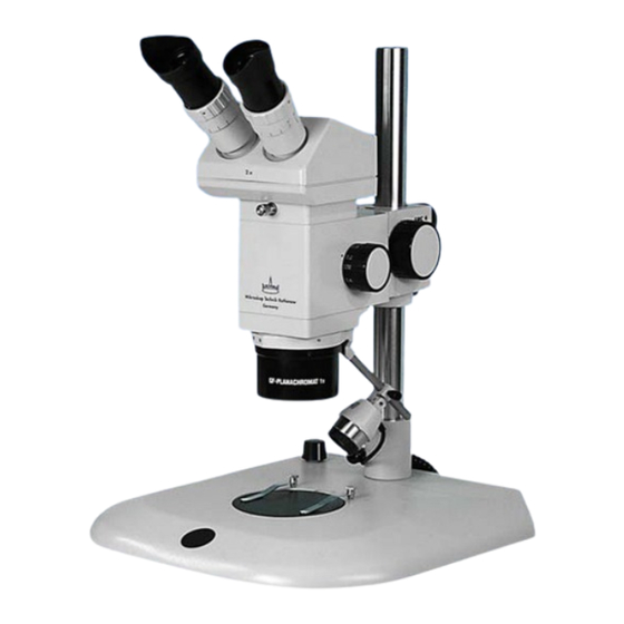
Always hold the microscope tightly when the knurled screw is loosened! Picture 33: Large stand with column 367 mm, LED transmitted light illumination and built-in power supply icture 34: Assembled SMT 4 at column stand... -
Page 29: Turntable
9.3. Turntable he Turntable is equipped with a 360° divi- sion for reproducible torsion of the object, as well as with table springs for holding the ob- ject being examined. With the centering screws, the table can be adjusted so that the Picture 36: Spherical stage rotating center aligns with the middle of the ob- ject to be observed. -
Page 30: Measuring Stage 50 X 50
9.6. Measuring stage 50 x 50 Mechanical stage 80 x 80 The Measuring stage 50x50 is for measuring The M hanical Stage 80x80 serve s for the bjects. It can be inserted into the standard in- stematic scrutinizing and the sensitive ad- cident light stand as well as in T/I base, and justment of objects. -
Page 31: Mechanical Stage K 150 And K 200
9.8. Mechanical stage K 150 and K 200 .8.2. For a fast and coarse alignment of bjects a handhold (1) can be found on the The Mechanical stages K 150 and K 200 are right site of the stage. The mechanical stage sed for the systematic scrutinizing of large ob- can be adjusted sensitive in x –y direction with jects up to 150 mm or 200 mm edge length. -
Page 32: Complaints, Warranty
No liability is accepted for printing errors. Mikroskop Technik Rathenow GmbH Grünauer Fenn 40 D-14712 Rathenow Telefon: +49 (0)3385 53710 Telefax: +49 (0)3385 537122 Internet: http://www.askania.de E-mail: mikro.ra@askania.de Date: August 2013...
Need help?
Do you have a question about the SMT 4 and is the answer not in the manual?
Questions and answers