
Subscribe to Our Youtube Channel
Related Manuals for Marquette 2000 series

Summary of Contents for Marquette 2000 series
- Page 1 Series 2000 Treadmill field service manual PN 409110-004 Revision D A PART OF THE MARQUETTE U N I T Y N E T W O R K...
- Page 2 Connect Spiral, RAMS, RSVP, SAM, SEER, SOLAR, SOLARVIEW, Spectra 400, Spectra-Tel, ST GUARD, TRAM, TRAM-NET, TRAM-RAC, TRAMSCOPE, TRIM KNOB, UNITY logo, UNITY NETWORK, Vari-X, Vari-X Cardiomatic, VariCath, VAS, and Vision Care Filter are trademarks of Marquette Medical Systems, Inc., registered in the United States Patent and Trademark Office.
-
Page 3: Table Of Contents
Contents Introduction ..........1-1 Manual Information ..............1-3 Revision History ................. 1-3 Manual Purpose ................. 1-3 Conventions ..................1-4 Safety Information ..............1-5 Responsibility of the Manufacturer ............ 1-5 General ....................1-5 Equipment Symbols ................1-6 Warnings and Cautions ..............1-7 Service Information .............. - Page 4 Equipment Overview ........2-1 General Description ..............2-3 Intended Use ..................2-3 Motor Drive System ................2-3 Elevation System ................2-3 Bed Assembly ..................2-3 Electronic Assembly ................2-3 Block Diagram ..................2-4 Preparation for Use ..............2-5 Safe Handling Guidelines ..............2-5 Equipment Assembly .................
- Page 5 Test #1 ....................3-7 Ground-Wire-Leakage-to-Ground ......... 3-7 Test #2 ....................3-7 Chassis-Leakage-to-Ground (Exposed Chassis) ....3-7 Test #3 ....................3-8 Patient-Cable-Leakage-to-Ground ......... 3-8 Test #4 ....................3-8 Patient Cable-Leakage-into-Patient Leads-from 120 VAC ..3-8 Ground Continuity Test ..............3-9 Self-Calibration ..............3-10 When to Calibrate ................
- Page 6 Control PCB Theory ..............4-13 General Description ................4-13 Power Distribution ................4-13 Clock Generator ................4-13 Reset Generator ................4-13 Temperature Sensor ................ 4-14 Processor Circuitry ................4-14 Analog Inputs ................... 4-14 Speaker Output ................4-14 Analog Outputs ................4-15 Analog Supplies ................
- Page 7 Elevation Motor Replacement ............. 4-34 Replacement Instructions ..............4-34 Electronics Box Replacement ............4-35 Replacement Instructions ..............4-35 Drive Motor Control Box Replacement ........... 4-36 Replacement Instructions ..............4-36 Parts Lists and Drawings for Configuration without CE ..........5A-1 Ordering Parts ..............
- Page 8 PCB Assemblies ........... 6-1 800320-001H Control PCB ............6-3 SD800320-001G Control PCB Schematic ......... 6-6 800334-003A Power PCB ............6-12 SD800334-003A Power PCB Schematic ......... 6-16 Appendices Appendix A: Abbreviations ....... A-1 Standard Abbreviations .............. A-3 Appendix B: Technical Description ...... B-1 Technical Specifications ............
-
Page 9: Introduction
Introduction Manual Information ..............3 Manual Purpose ..................3 Conventions ................... 4 Safety Information ............... 5 General ....................5 Equipment Symbols ................6 Warnings and Cautions ................7 Service Information ..............9 Equipment Identification ................ 9 Series 2000 Treadmill Revision D 409110-004... - Page 10 Series 2000 Treadmill Revision D 409110-004...
-
Page 11: Manual Information
Introduction : Manual Information Manual Information Revision History Each page of the document has the document part number followed by a revision letter at the bottom of the page. This letter identifies the document’s update level. The latest letter of the alphabet corresponds to the most current revision of the document. -
Page 12: Conventions
Introduction : Manual Information Conventions These are the conventions used in this manual. Safety Messages DANGER safety messages indicate an imminently hazardous situation which, if not avoided, WILL result in death or serious injury. WARNING safety messages indicate a potentially hazardous situation which, if not avoided, COULD result in death or serious injury. -
Page 13: Safety Information
Introduction : Safety Information Safety Information Responsibility of the Marquette Medical Systems, is responsible for the effects of safety, reliability, and performance only if: Manufacturer Assembly operations, extensions, readjustments, modifications, or repairs are carried out by persons authorized by Marquette. -
Page 14: Equipment Symbols
Introduction : Safety Information Equipment Symbols The following symbols appear on the equipment. This symbol means that you must pay attention to the documents delivered with this equipment. It calls attention to the things to which you must pay special attention during operation and when the equipment is operated in conjunction with other equipment. -
Page 15: Warnings And Cautions
Introduction : Safety Information Warnings and Cautions DANGER WARNING Do NOT use in the Total system leakage presence of flammable current must not anesthetics. exceed 300 M15287-1B microamperes. M15287-76A WARNING WARNING Replace only with the same type and rating Wait until treadmill belt is moving before of fuse. - Page 16 Introduction : Safety Information WARNING WARNING Operate the treadmill Verify proper operation with 6 feet of clearance of the stop switch at the rear (end opposite assembly, pn 88380-006, the motor). every month. M15287-066A M15287-065A Series 2000 Treadmill Revision D 409110-004...
-
Page 17: Service Information
Any unauthorized attempt to repair equipment under warranty voids that warranty. It is the user’s responsibility to report the need for service to Marquette Medical Systems or to one of their authorized agents. Failure on the part of the responsible individual, hospital, or institution using this equipment to implement a satisfactory maintenance schedule may cause undue equipment failure and possible health hazards. - Page 18 Introduction : Service Information 1-10 Series 2000 Treadmill Revision D 409110-004...
-
Page 19: Equipment Overview
Equipment Overview General Description ..............3 Intended Use ..................3 Motor Drive System ................3 Elevation System ..................3 Bed Assembly ..................3 Electronic Assembly ................3 Block Diagram ..................4 Preparation for Use ..............5 Equipment Assembly ................6 Handle Set ................6 Emergency Stop Switch ............7 Connector Locations ................ - Page 20 Series 2000 Treadmill Revision D 409110-004...
-
Page 21: General Description
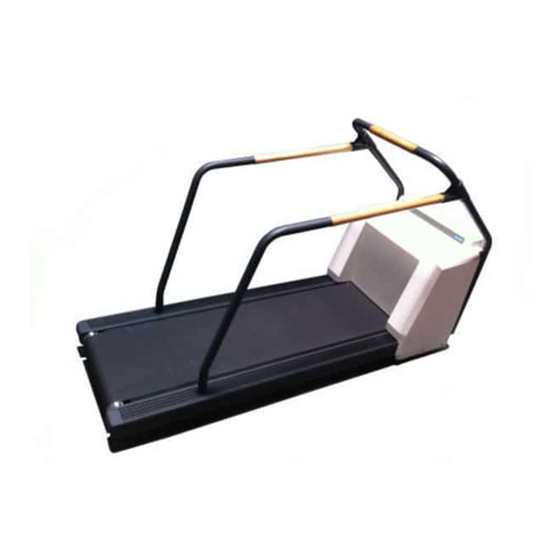
Intended Use The Series 2000 Treadmill is intended for use with any one of the several Marquette Medical Systems exercise testing systems or the MTC-1 (manual treadmill controller) for administering a controlled exercise load during a diagnostic stress test. -
Page 22: Block Diagram
Equipment Overview : General Description Block Diagram MD1129-007E Series 2000 Treadmill Revision D 409110-004... -
Page 23: Preparation For Use
Equipment Overview : Preparation for Use Preparation for Use Safe Handling The Series 2000 Treadmill ships preset with an approximate 2% grade. This slight elevation provides for free wheel movement and prevents the Guidelines shroud from scraping the floor. If you are moving the treadmill after it has been in operation, use the controlling equipment to set the grade to approximately 7%. -
Page 24: Equipment Assembly
Equipment Overview : Preparation for Use Equipment Assembly The Series 2000 Treadmill ships completely assembled except for the handle set and the emergency stop switch. Attach the handle set and emergency stop switch before applying power to the unit. NOTE As recommended by the American Heart Association Exercise Standards (Special Report, Vol 82, No 6), the treadmill... -
Page 25: Emergency Stop Switch
Equipment Overview : Preparation for Use 4. Attach the side rails to the front rail with the mated T-brackets. Tighten the two T-bracket bolts with the Allen wrench. Bolts T-bracket 2 Places Align the side rails to the predrilled guide holes in the front rails. -
Page 26: Connector Locations
Equipment Overview : Preparation for Use Connector Locations The illustration below shows the various input connectors on the rear panel of the treadmill. Attach the appropriate controller cable from the stress system or MTC-1 and the AC power cable. WARNING Route the AC power cable away from moving parts. -
Page 27: Operating Instructions
Electrical Safety Tests The electrical safety of this installation is the responsibility of the customer, not Marquette Medical Systems. In hospitals, contact your in- house biomedical technician, electrician, or technically qualified personnel. Outside of hospitals, contact your hospital affiliation for these services. -
Page 28: Emergency Stop Switch
Equipment Overview : Operating Instructions Controlling the Treadmill Turn the power switch on (1). Use the controlling equipment to start the treadmill, adjust the treadmill speed and grade, proceed through the exercise phases, terminate the exercise session, and turn off the treadmill. WARNING Wait until treadmill belt is moving before... -
Page 29: Maintenance
Maintenance Introduction ................3 Recommended Maintenance ..............3 Inspection Report ..............3 Required Tools and Supplies ..............3 Inspection and Cleaning ..............4 Visual Inspection ..................4 Exterior Cleaning ..................4 Interior Cleaning ..................4 Domestic Electrical Safety Tests ............5 AC Line Voltage Test ................ - Page 30 Series 2000 Treadmill Revision D 409110-004...
-
Page 31: Introduction
Self-calibration Belt tracking adjustments Inspection Report To help you establish a systematic maintenance routine, Marquette Medical Systems recommends that, every six months, you perform the maintenance checks and test procedures on the “Preventive Maintenance Inspection Report,” included at the end of this chapter. -
Page 32: Inspection And Cleaning
Maintenance : Inspection and Cleaning Inspection and Cleaning Visual Inspection Regularly inspect the AC power cord and all other cords and cables for fraying or other damage. Perform safety tests on any repaired line cords. Inspect all plugs, cables and connectors for bent prongs or pins. Verify that all cords, socketed components, and connectors are securely seated. -
Page 33: Domestic Electrical Safety Tests
Maintenance : Domestic Electrical Safety Tests Domestic Electrical Safety Tests AC Line Voltage Test This test verifies that the domestic wall outlet supplying power to the equipment is properly wired. For international wiring tests, refer to the internal standards agencies of that particular country. 120 VAC, 50/60 Hz Use a digital voltmeter to check the voltages of the 120-volt AC wall outlet (dedicated circuit recommended). -
Page 34: Leakage Tests
Call Tech Support for assistance. (See the “How to Reach Us” page in the front of the manual.) Marquette Medical Systems recommends that you perform these tests: Before applying power for the first time Every 6 months as part of routine maintenance... -
Page 35: Leakage Test Diagrams
Maintenance : Domestic Electrical Safety Tests Leakage Test Diagrams These diagrams show only a representation of how a typical leakage current tester functions. Follow the instructions provided with the leakage current tester that you use. Test #1 Ground-Wire-Leakage-to-Ground “To be tested” power connector on back of tester (may not be labeled on some testers). -
Page 36: Test #3
Maintenance : Domestic Electrical Safety Tests Test #3 Patient-Cable-Leakage-to-Ground “To be tested” power connector on back of tester (may not be labeled on some testers). Tester Tester Polarity power Norm cord power Line cord Line Neutral Unit under Neutral test (UUT) Meter Patient cable... -
Page 37: Ground Continuity Test
Maintenance : Domestic Electrical Safety Tests This test verifies that there is continuity (less than 100 m Ω resistance) Ground Continuity Test between all the exposed metal surfaces, which have the potential to become energized, and the ground prong on the mains AC power cord. If the metal surfaces are anodized or painted, scrape off a small area in an inconspicuous area on the aluminum casting for the probe to make direct contact with the metal. -
Page 38: Self-Calibration
Maintenance : Self-Calibration Self-Calibration When to Calibrate Marquette Medical Systems recommends that you activate the self-calibration feature every time you replace a major assembly or a circuit board. Activating To activate the Series 2000 Treadmill self-calibration feature, do the following: Self-Calibration 1. -
Page 39: Belt Tracking Adjustments
Maintenance : Belt Tracking Adjustments Belt Tracking Adjustments WARNING Keep hands, hair, jewelry, and loose clothing away from moving parts. M15287-26B When to Adjust The treadmill walking-belt tension is set at the factory. However, you should test the belt tracking every time the treadmill is moved. Run the treadmill for several minutes with no one exercising. -
Page 40: Adjust Pulley Screws
Maintenance : Belt Tracking Adjustments Adjust Pulley Screws 1. Use the controlling equipment to set the belt speed to 4 or 5 miles per hour (7 or 8 kilometers per hour). 2. To correct a belt that tracks to the right, turn the right pulley adjustment screw CLOCKWISE in 1/8-turn increments until the belt tracks in the center. -
Page 41: Miscellaneous Maintenance Forms
Maintenance : Miscellaneous Maintenance Forms Miscellaneous Maintenance Forms Marquette Medical Systems recommends that every six months you perform the maintenance checks and test procedures on the “Preventive Maintenance Inspection Report” (see following page). These maintenance procedures can be performed more often if indicated. - Page 42 Maintenance : Miscellaneous Maintenance Forms 3-14 Series 2000 Treadmill Revision D 409110-004...
- Page 43 Series T2000 Treadmill DPMFRM-003B Preventive Maintenance Inspection Report 31 July 1998 Page 1 of 3 Customer______________________________ Customer Number______________________ Date___________ FE ___________________________________ FE ID________ Call Number______________________________ Equipment Serial Number_________________ Software Revision _________ Configuration ( ___ Emergency Stop Switch installed Tools 1. Leakage tester 3.
- Page 44 DPMFRM-003B Page 2 of 3 Comments Briefly describe all repairs/adjustments made and list all parts replaced: ___________________________________________________________________________________________________ ___________________________________________________________________________________________________ Additional comments: ___________________________________________________________________________________________________ ___________________________________________________________________________________________________ Template Revision C...
-
Page 45: Power Pcb
FRU Checkout Procedure Tools Visual Cleaning Calibration Electrical Checkout Description* Inspection Safety Tests Procedure Drive Controller Box(Thor) 1,3,8 1,3,8 Control(CPU) Pcb 1,3,8 Power Pcb Drive Belt Walking Belt Walking Board 1,5,8 3 HP Speed Motor 2,6,8 Elevation Motor 1,4,5,7 Front Roller 1,4,5,7 Rear Roller Software... -
Page 47: Troubleshooting
Troubleshooting Power PCB Theory ............... 3 General Description ................3 Power Distribution/Isolation ..............3 STOP Circuitry ..................3 Frequency-to-Voltage Converter/Amplifier ..........3 Start/Stop Circuitry ................4 Elevation Relays ..................4 Drive Connector ..................4 Hall Feedback ..................4 Power Inlet, Drive Power Outlet, and Mains ........... 4 Control Board Connector ............... - Page 48 Drive Motor Control Box Description ..........17 Power Board ..................17 Control Board ..................17 LED Functions ..................17 User Inputs/Outputs ................19 Electrical Requirements ............... 21 General Fault Isolation ............... 22 Visual Inspection .................. 22 Power Down ................22 Shroud Removal .................. 23 Parts Locations ..................
-
Page 49: Power Pcb Theory
Troubleshooting : Power PCB Theory Power PCB Theory General Description The 800334-002 power board and the 800320-001 control board function together as part of the electronics box to control the Series 2000 Treadmill. The power board contains the following: Mains components Isolation transformer Elevation and drive interface circuitry Speaker (for error codes) -
Page 50: Start/Stop Circuitry
Troubleshooting : Power PCB Theory Start/Stop Circuitry When COAST* and BRAKE* are not active (low), the START pulse command can engage the drive system. These signals are level converted from CMOS/TTL (0–5 V) levels to (-15 V–0 V) logic by the 74HC14 drivers and level shifting transistors. -
Page 51: Elevation Sensor
Troubleshooting : Power PCB Theory Elevation Sensor The elevation sensor is a 5-turn pot that is coupled to the elevation rack. The voltage on pin 2 should be proportional to elevation. That is, low voltage should be low elevation, increasing voltage should indicate increasing elevation. -
Page 52: Esd And Emi Compatibility
Troubleshooting : Power PCB Theory ESD and EMI The I/O connectors on the power board have current-limiting resistors, Zener diodes, or filtering capacitors wherever possible to prevent EMI Compatibility from escaping the board. These components also limit rise-time and voltages which may come from ESD or other noise sources. Power Supply Requirements Table 4-1. - Page 53 Troubleshooting : Power PCB Theory Table 4-2. J2 Debug/Analog Control PIN # NAME TYPE IN/OUT FREQ COMMENT J2-1 SPEEDV Current Speed 1V/5MPH (±2% TOLERANCE) J2-2 TXSERVICE 10KHZ RS-232 (NOT WORKING) DEBUG T J2-3 RXSERVICE 10KHZ RS-232 (NOT WORKING) DEBUG RX J2-4 MANELEV MAN ELEV IN 0-5V...
- Page 54 Troubleshooting : Power PCB Theory Table 4-3. J5 Drive Connector (Continued) J5-13 TEMP2 LEVEL OverTemp cutout J5-14 HALL5 OC5V 10KHZ Hall sensor 5 /Tach B J5-15 HALL4 OC5V 10KHZ hall sensor 4/Tach A J5-16 SHLD-GND Digital Ground Table 4-4. J6 Elevation Motor NAME TYPE IN/OUT...
- Page 55 Troubleshooting : Power PCB Theory Table 4-6. J9 CPU Board Interface–I/O and Power PIN # NAME TYPE IN/OUT FREQ. COMMENTS J9-1 Digital Ground J9-2 +5V SUPPLY J9-3 Digital Ground J9-4 +5V SUPPLY J9-5 START CMOS PULSE Belt START pulse (latched) J9-6 BRAKE* CMOS...
- Page 56 Troubleshooting : Power PCB Theory Table 4-6. J9 CPU Board Interface–I/O and Power (Continued) J9-27 SELF-CAL CMOS LEVEL Signal to Start SELFCAL J9-28 TXSERVICE 10KHZ RS232 DEBUG TX J9-29 MANRUN CMOS LEVEL Signal to Start MAN CNTRL J9-30 RXSERVICE 10KHZ RS232 DEBUG RX J9-31 FAULT*...
- Page 57 Troubleshooting : Power PCB Theory Table 4-7. J12 Hall Sensor Interface PIN # NAME TYPE IN/OUT FREQ. COMMENTS COLOR J12-1 DRVGND Digital Ground J12-2 DRV5V Hall sensor power J12-3 HALL3 OC5V 10KHZ Hall sensor 3 J12-4 HALL2 OC5V 10KHZ Hall sensor 2 J12-5 HALL4 OC5V...
-
Page 58: Precautions
Troubleshooting : Power PCB Theory Precautions The Board must be powered before signals are applied to it. The circuitry is static sensitive as are all HC, AC, and MOS ICs. Therefore, when removing or installing boards, the power should be off. The circuit board should not be supplied with a VCC over 5.5 volts on the +5V supply. -
Page 59: Control Pcb Theory
Troubleshooting : Control PCB Theory Control PCB Theory General Description The 800320-001 control board and the 800334-002 power board function together to control the Series 2000 Treadmill. The control board contains the following: Micro-controller CPU circuitry (78310) Memory (EEROM code/calibration/history data, SRAM) Temperature sensor Speaker driver Some of the I/O circuitry... -
Page 60: Temperature Sensor
Troubleshooting : Control PCB Theory Temperature Sensor The processor monitors temperature and saves peak temperature in EEROM data storage for use by field service. The sensor outputs 10 mV/Deg C. The op amp provides a gain of 4.92. The 78310 A/D converter produces the following outputs In hardware: A/D value = Temp(Deg C) * 10mV/DegC * GAIN * 256(max A/D counts) / VREF In software: Readout Temp = (A/D value) * 4 / 10... -
Page 61: Analog Outputs
Troubleshooting : Control PCB Theory Analog Outputs Two analog outputs are derived from the two PWM (pulse-width modulation) output channels. The 8-bit register for the PWM pulses are used to control an analog switch which provides precise 1.235 V pulses to an integrator. -
Page 62: Brushless Dc Drive Theory
Any speed error results in an output from the integrator that builds with time and causes an output to the current loop. This loop, therefore, will seek zero speed error. This is the type of velocity loop used in the Marquette Series 2000 Treadmill drive. 4-16 Series 2000 Treadmill... -
Page 63: Drive Motor Control Box Description
Troubleshooting: Drive Motor Control Box Description Drive Motor Control Box Description Power Board The treadmill drive motor control consists of two PC boards and a power IGBT module. The power board is located on the heat sink and contains the input bridge rectifier, the DC bus capacitors, the logic power supplies, and the IGBT gate drivers. - Page 64 Troubleshooting: Drive Motor Control Box Description Power (Power Supplies OK) This LED lights when the main ± 15-volt power supplies are within the required range. Tach loss This LED lights to indicate the tachometer circuits in the motor are not active.
-
Page 65: User Inputs/Outputs
Troubleshooting: Drive Motor Control Box Description User Inputs/Outputs User inputs and outputs are available at the 15-pin, D-connector located at the top of the drive. See figure for a list of the functions and pin numbers. Signal functions are as follows: HALL1, HALL2, HALL3 These signals originate from the commutation hall sensors in the DC motor and are used to decode the rotor position so that the correct... - Page 66 Troubleshooting: Drive Motor Control Box Description FAULT This is an open collector output that is pulled low when a fault condition is latched. TEMP1, TEMP2 These terminals can be connected to an external thermal switch such as the motor over-temperature switch. The switch should be normally closed.
-
Page 67: Electrical Requirements
Troubleshooting: Drive Motor Control Box Description Electrical Requirements The two black wires that exit the side of the enclosure supply power to the drive. The power source should be single phase, 208/240 VAC. If the line voltage dips below 170 VAC or exceeds 264 VAC, the drive faults. Maximum input current is 16A. -
Page 68: Pcb Assemblies
Troubleshooting: General Fault Isolation General Fault Isolation Visual Inspection A thorough visual inspection of the equipment can save time. Small things—disconnected cables, foreign debris on circuit boards, missing hardware, loose component—can frequently cause symptoms and equipment failures that may appear to be unrelated and difficult to track. -
Page 69: Shroud Removal
Troubleshooting: General Fault Isolation Table 4-8. Visual Inspection List Area Look for the following problems: I/O Connectors and Cables • Fraying or other damage.• Bent prongs or pins. • Cracked housing.• Loose screws in plugs. Fuses • Type and rating. Replace as necessary. Interface Cables •... -
Page 70: Parts Locations
Troubleshooting: General Fault Isolation Parts Locations chassis ground WARNING isolated ground Electrical shock hazard between chassis ground and isolated (“floating”) ground when power is applied. Unplug unit from power source before proceeding. M15287-61A Electronics Box Connector Panel Elevation Pot (under Electronics Box) Fly Wheel Elevation Motor Motor Control Box... -
Page 71: Power Supply Voltage Checks
Troubleshooting: General Fault Isolation Power Supply Voltage With the power on, remove the side panel on the electronics box to measure the system’s supply voltages as follows: Checks On the control board, PN 800320-001, check the voltages on pins 2, 34, and 36 in reference to digital ground (see illustration). The control board is mounted on the power board. -
Page 72: Drive Control Fault Leds
Troubleshooting: General Fault Isolation Drive Control Fault LEDs Use a hand-held mirror to view fault indicator LEDs. Over temp Fault Ilim Power Tach loss MD1129-023A 4-26 Series 2000 Treadmill Revision D 409110-004... -
Page 73: Dc Motor Replacement
Troubleshooting: DC Motor Replacement DC Motor Replacement Replacement 1. Turn the power switch off, disconnect the power cord from the wall outlet, and remove the shroud. Instructions 2. Unscrew the 6 screws on the electronics box side panel and remove the panel. 3. - Page 74 Troubleshooting: DC Motor Replacement 7. Lift the treadmill up on end. This treadmill position offers the best access for replacing the DC motor. 8. Use a 1/2-inch wrench to remove the 4 nuts that hold the motor in place (2 each side). Mounting Nuts 4 Places Drive Belt Tension...
-
Page 75: Front Roller Replacement
Troubleshooting: Front Roller Replacement Front Roller Replacement Replacement 1. Turn the power switch off, disconnect the power cord from the wall outlet, and remove the shroud. Instructions 2. Loosen the walking belt tension bolts on the end of the treadmill. Tension Bolts MD1129-016B 3. -
Page 76: Walking Belt And Board Replacement
Troubleshooting: Walking Belt and Board Replacement Walking Belt and Board Replacement Walking Belt 1. Turn the power switch off, disconnect the power cord from the wall outlet, and remove the shroud. You do not have to remove Replacement the roller to replace the belt. Instructions 2. -
Page 77: Walking Board Replacement Instructions
Troubleshooting: Walking Belt and Board Replacement 5. Slide the bracket into the frame. 6. Slide the belt off the walking board, lower end first. 7. Replace the belt in reverse order. NOTE The wax material on the walking board acts as a lubricant for the belt. -
Page 78: Motor Drive Belt Replacement And Adjustments
Troubleshooting: Motor Drive Belt Replacement and Adjustments Motor Drive Belt Replacement and Adjustments Tension Adjustments 1. Turn the power switch off, disconnect the power cord from the wall outlet, and remove the shroud. 2. To replace the drive belt, first remove the front roller as instructed in this chapter under “Front Roller Replacement.”... -
Page 79: Tracking Adjustments
Troubleshooting: Motor Drive Belt Replacement and Adjustments 5. Fine tune the belt tension with the adjustment bolts so that you can push in the belt approximately 1/2-inch on one side. NOTE Excessive tension will cause undue stress on the motor shaft. With firm pressure applied to belt midway between pulleys, distance must be at least 1/2 inch between top of belt and 12 inch (minimum) length straight edge. -
Page 80: Elevation Motor Replacement
Troubleshooting: Elevation Motor Replacement Elevation Motor Replacement Replacement 1. Turn the power switch off, disconnect the power cord from the wall outlet, and remove the shroud. Instructions 2. Disconnect the elevation motor power cable and remove all tie wraps on the cable. 3. -
Page 81: Electronics Box Replacement
Troubleshooting: Electronics Box Replacement Electronics Box Replacement Replacement 1. Turn the power switch off, disconnect the power cord from the wall outlet, and remove the shroud. Instructions 2. Unscrew the 6 screws on the electronics box side panel and remove the panel. 3. -
Page 82: Drive Motor Control Box Replacement
Troubleshooting: Drive Motor Control Box Replacement Drive Motor Control Box Replacement Replacement 1. Turn the power switch off, disconnect the power cord from the wall outlet, and remove the shroud. Instructions 2. Unscrew 6 screws on the electronics box side panel and remove the panel. -
Page 83: Parts Lists And Drawings For Configuration Without
Parts Lists and Drawings for Configuration without CE Ordering Parts ................. 3 Introduction ................... 3 Field Replaceable Units For Product CodeY5 (non-CE) ......4 Rev R Upper-Level Assembly ..........5 900433-001G Full Handrail Kit............. 6 900367-001T Treadmill Assembly ..........7 900418-101B Electronics Box Assembly ........ - Page 84 Series 2000 Treadmill 5A-2 Revision D 409110-004...
-
Page 85: Ordering Parts
Parts Lists and Drawings for Configuration without CE : Ordering Parts Ordering Parts Introduction This chapter contains the current parts lists, drawings, some schematics, and any kits for the standard treadmill configurations available at the time of the manual release date. The upper-level parts list appears first, followed by the assembly parts. -
Page 86: Field Replaceable Units For Product Codey5 (Non
Parts Lists and Drawings for Configuration without CE : Field Replaceable Units For Product CodeY5 (non-CE) Field Replaceable Units For Product CodeY5 (non-CE) The following items may not be assigned separate manufacturing part numbers because they are normally part of a larger assembly. Since they are considered field replaceable units (FRUs), they have specific service part numbers so they can be ordered and replaced by service technicians... - Page 87 Parts Lists and Drawings for Configuration without CE : Upper-Level Assembly Rev R Upper-Level Assembly Rev R Item Description Part Number 2000 TRDML W/FULL HNDL DOM 900444-001 2000 TRDML W/FULL HNDL INTL 900444-002 2000 TRDML W/EMI FULL HNDL DOM 900444-003 2000 TRDML W/EMI FULL HNDL INT 900444-004 CABLE TRDML/CASE INTCON...
-
Page 88: Full Handrail Kit
Parts Lists and Drawings for Configuration without CE : Full Handrail Kit 900433-001G Full Handrail Kit 900433-001G Item Description Part Number SOCKET ALLEN 3/16 HEX 400056-001 HANDLE-T 400093-001 SCREW SKT 1/4-20 X 3/4 407236-001 SCREW SKT 1/4-20 X 1.63 407236-002 BOX MAILER 11.75L 11.00W 2.88H 9924-101 KIT TEE HANDLE LH-RH... -
Page 89: Treadmill Assembly
Parts Lists and Drawings for Configuration without CE : Treadmill Assembly 900367-001T Treadmill Assembly 900367-001T Item Description Part Number BELT WALKING 1800/1900/2000 3602-006 SCREW SKT 1/4-20 X 1.00L 407236-003 EXTRUSION SIDE RAIL T2000 413690-001 MOTOR ELEVATION 185-265V .13HP 408890-001 MOTOR 3HP 4000 RPM DC-QUIET 408893-002 CLAMP HANDRAIL TERM TO BASE 408894-001... - Page 90 Parts Lists and Drawings for Configuration without CE : Treadmill Assembly 900367-001T Item Description Part Number PANEL POT ISO FROM TOWER 408929-001 BRKT DRIVE MTR MOUNTING 408931-001 LABEL 2000T SHROUD 410465-001 CONTROL BOX DRIVE MOTOR CE MRK 408891-002 KEY 3/16 X 3/16 X 7/16 410625-001 SCREW GR8 1/4-20 X .88 45002-114...
- Page 91 Parts Lists and Drawings for Configuration without CE : Treadmill Assembly 900367-001T Item Description Part Number 1/4-20X5/8 SKTCAP SCREW W/NYL 45023-212 SCREW SEMS PH 1/4-20 .625L 45000-710 HARN EBOX TO CNTRLR RBN 16 PIN 700337-002 NUT 5/16-18 FLANGED LOCKING 410686-001 SCREW HEX 5/16-18 FLANGED LK 410686-002 GREASE SYNTHETIC WITH TEFLON...
- Page 92 Parts Lists and Drawings for Configuration without CE : Treadmill Assembly 900367-001T 1 of 4 Tension to 1/2% 8 PL 900433-001 Ref 2 PL 4 PL 4 PL 4 PL 900433-001 Ref Tension belt 45 LBS. - 55 LBS. 3 PL 3 PL 6 PL 8 PL...
- Page 93 Parts Lists and Drawings for Configuration without CE : Treadmill Assembly 900367-001T 2 of 4 4 PL 2 PL 4117929-003 Ref 4 PL See note below 8 PL 2 PL -001 -002 410465-005 Ref 2 PL 2 PL 2 PL 4 PL 4 PL 6 PL...
- Page 94 Parts Lists and Drawings for Configuration without CE : Treadmill Assembly 900367-001T 3 of 4 2 PL 4 PL 2 PL To J8 View A From Lead ITEM Circuit ITEM Circuit ITEM Ident. Point Point – – – 81, 66 S2, S3 81, 66 MOTOR...
- Page 95 Parts Lists and Drawings for Configuration without CE : Treadmill Assembly 900367-001T 4 of 4 Revision D Series 2000 Treadmill 5A-13 409110-004...
-
Page 96: Electronics Box Assembly
Parts Lists and Drawings for Configuration without CE : Electronics Box Assembly 900418-101B Electronics Box Assembly 900418-101B Item Description Part Number PLUG MC EQUIPOTENTIAL 400040-001 SWITCH CKT BRKR 240V 20A 408759-001 PANEL SVC ACCESS TMILL-2000 408927-001 PANEL RFI/EMI SHIELD 9-PIN D 408928-101 KIT ELECTRONICS BOX 408932-106... - Page 97 Parts Lists and Drawings for Configuration without CE : Electronics Box Assembly 900418-101B 408932-105 Location of UID Label (Ref) Serial Number Label 2 PL Ref 404525-001 locate with Bar Code to outer edge 417929-002 4 PL 4 PL 6 PL 4 PL 4 PL 3 PL...
-
Page 98: Stop Switch Assembly
Parts Lists and Drawings for Configuration without CE : Stop Switch Assembly 88380-006B Stop Switch Assembly 88380-006B Item Description Part Number SWITCH SPST NC 1668-001 ACTUATOR EMER PB 1668-101 CLAMP EMERGENCY STOP T-2000 402183-003 SCREW FH 6-32X.38 R 45009-606 NUT HEX KEPS 4-40 4521-704 CLAMP CORD MEDIUM 4528-006... - Page 99 Parts Lists and Drawings for Configuration without CE : Stop Switch Assembly 88380-006B See Note 2 Apply over Item 17. Ref. 10.00 FT Notes: 4 PL 1. Place Items 3, 6, 11, and 12 in a plastic bag. 2. Item #17 to read: I st Line: (Part number) 2 nd Line: (Lot code) 2 PL...
- Page 100 Parts Lists and Drawings for Configuration without CE : Stop Switch Assembly 88380-006B 5A-18 Series 2000 Treadmill Revision D 409110-004...
-
Page 101: Parts Lists And Drawings For Configuration With
Parts Lists and Drawings for Configuration with CE Ordering Parts ................. 3 Field Replaceable Units for Product Code Y5 w/CE ........ 4 Rev R Upper-Level Assembly ..........5 900444-00XG 50/60 Hz Full Handle Assembly ........6 900433-001G Full Handrail Kit............. 6 900367-002T Treadmill Assembly w/CE ......... - Page 102 Series 2000 Treadmill 5B-2 Revision D 409110-004...
-
Page 103: Ordering Parts
Parts Lists and Drawings for Configuration with CE : Ordering Parts Ordering Parts Introduction This chapter contains the current parts lists, drawings, some schematics, and any kits for the standard treadmill configurations available at the time of the manual release date. The upper-level parts list appears first, followed by the assembly parts. -
Page 104: Field Replaceable Units For Product Code Y5 W
Parts Lists and Drawings for Configuration with CE : Field Replaceable Units for Product Code Y5 w/CE Field Replaceable Units for Product Code Y5 w/CE The following items may not be assigned separate manufacturing part numbers because they are normally part of a larger assembly. Since they are considered field replaceable units (FRUs), they have specific service part numbers so they can be ordered and replaced by service technicians. - Page 105 Parts Lists and Drawings for Configuration with CE : Upper-Level Assembly Rev R Upper-Level Assembly Rev R Item Description Part Number 2000 TRDML W/FULL HNDL DOM 900444-001 2000 TRDML W/FULL HNDL INTL 900444-002 2000 TRDML W/EMI FULL HNDL DOM 900444-003 2000 TRDML W/EMI FULL HNDL INT 900444-004 CABLE TRDML/CASE INTCON...
-
Page 106: Full Handrail Kit
Parts Lists and Drawings for Configuration with CE : 50/60 Hz Full Handle Assembly 900444-00XG 50/60 Hz Full Handle Assembly 900444-00XG Item Description Part Number 2000 TRDML W/FULL HNDL DOM 900444-001 2000 TRDML W/FULL HNDL INTL 900444-002 2000 TRDML W/EMI FULL HNDL DOM 900444-003 2000 TRDML W/EMI FULL HNDL INT 900444-004... -
Page 107: Treadmill Assembly W
Parts Lists and Drawings for Configuration with CE : Treadmill Assembly w/CE 900367-002T Treadmill Assembly w/CE 900367-002T Item Description Part Number SCREW SKT 1/4-20 X 1.00L 407236-003 EXTRUSION SIDE RAIL T2000 413690-001 MOTOR ELEVATION 185-265V .13HP 408890-001 MOTOR 3HP 4000 RPM DC-QUIET 408893-002 CLAMP HANDRAIL TERM TO BASE 408894-001... - Page 108 Parts Lists and Drawings for Configuration with CE : Treadmill Assembly w/CE 900367-002T Item Description Part Number BRKT DRIVE MTR MOUNTING 408931-001 LABEL 2000T SHROUD 410465-001 CONTROL BOX DRIVE MOTOR CE MRK 408891-002 KEY 3/16 X 3/16 X 7/16 410625-001 SCREW GR8 1/4-20 X .88 45002-114 STUD FULL THREAD GR...
- Page 109 Parts Lists and Drawings for Configuration with CE : Treadmill Assembly w/CE 900367-002T Item Description Part Number NUT 5/16-18 FLANGED LOCKING 410686-001 SCREW HEX 5/16-18 FLANGED LK 410686-002 GREASE SYNTHETIC WITH TEFLON 410748-001 0.06 BUMPER PLASTIC 1.00 OD 410746-001 SCREW SEMS PH PHIL 4-40 X.312L 45000-405 SPLICE CE 22-14 4533-201...
- Page 110 Parts Lists and Drawings for Configuration with CE : Treadmill Assembly w/CE 900367-002T 1 of 4 Tension to 1/2% 8 PL 900433-001 Ref 2 PL 4 PL 4 PL 4 PL 900433-001 Ref Tension belt 45 LBS. - 55 LBS. 3 PL 3 PL 6 PL...
- Page 111 Parts Lists and Drawings for Configuration with CE : Treadmill Assembly w/CE 900367-002T 2 of 4 4 PL 2 PL 4117929-003 Ref 4 PL See note below 8 PL 2 PL -001 -002 410465-005 Ref 2 PL 2 PL 2 PL 4 PL 4 PL 6 PL...
- Page 112 Parts Lists and Drawings for Configuration with CE : Treadmill Assembly w/CE 900367-002T 3 of 4 2 PL 4 PL 2 PL To J8 View A From Lead ITEM Circuit ITEM Circuit ITEM Ident. Point Point – – – 81, 66 S2, S3 81, 66 MOTOR...
- Page 113 Parts Lists and Drawings for Configuration with CE : Treadmill Assembly w/CE 900367-002T 4 of 4 Revision D Series 2000 Treadmill 5B-13 409110-004...
-
Page 114: Electronics Box Assembly W
Parts Lists and Drawings for Configuration with CE : Electronics Box Assembly w/CE 900418-102B Electronics Box Assembly w/CE 900418-102B Item Description Part Number PLUG MC EQUIPOTENTIAL 400040-001 SWITCH CKT BRKR 240V 20A 408759-001 PANEL SVC ACCESS TMILL-2000 408927-001 PANEL RFI/EMI SHIELD 9-PIN D 408928-101 KIT ELECTRONICS BOX 408932-106... - Page 115 Parts Lists and Drawings for Configuration with CE : Electronics Box Assembly w/CE 900418-102B 408932-105 Location of UID Label (Ref) Serial Number Label 2 PL Ref 404525-001 locate with Bar Code to outer edge 417929-002 4 PL 4 PL 6 PL 4 PL 4 PL 3 PL...
-
Page 116: Stop Switch Assembly
Parts Lists and Drawings for Configuration with CE : Stop Switch Assembly 88380-006B Stop Switch Assembly 88380-006B Item Description Part Number SWITCH SPST NC 1668-001 ACTUATOR EMER PB 1668-101 CLAMP EMERGENCY STOP T-2000 402183-003 SCREW FH 6-32X.38 R 45009-606 NUT HEX KEPS 4-40 4521-704 CLAMP CORD MEDIUM 4528-006... - Page 117 Parts Lists and Drawings for Configuration with CE : Stop Switch Assembly 88380-006B See Note 2 Apply over Item 17. Ref. 10.00 FT Notes: 4 PL 1. Place Items 3, 6, 11, and 12 in a plastic bag. 2. Item #17 to read: I st Line: (Part number) 2 nd Line: (Lot code) 2 PL...
- Page 118 Parts Lists and Drawings for Configuration with CE : Stop Switch Assembly 88380-006B 5B-18 Series 2000 Treadmill Revision D 409110-004...
- Page 119 PCB Assemblies 800320-001H Control PCB ............3 SD800320-001G Control PCB Schematic ..........6 800334-003A Power PCB ............12 SD800334-003A Power PCB Schematic ........... 16 Series 2000 Treadmill Revision D 409110-004...
- Page 120 Series 2000 Treadmill Revision D 409110-004...
- Page 121 PCB Assemblies : Control PCB 800320-001H Control PCB 800320-001H Item Description Part Number RES SM CER 100 5% 1/8W 1081-101 RES SM CER 10K 5% 1/8W 1081-103 RES SM CHIP 68K 5% 1/8W 1081-491 RES SM CER 100K 1% 1/8W 1082-100 RES SM CER 4.99K 1% 1/8W 1082-101...
- Page 122 PCB Assemblies : Control PCB 800320-001H Item Description Part Number IC SM TEMP SENSOR LM35DM 410121-001 CKT BD 2000 TRDMILL CONTROL 800321-001 SCHEM 2000 TREADMILL CONTROL SD800320-001 RES SM CHIP 300 5% 1/8W 1081-497 CAP SM CER COG 22PF 5% 100V 1181-220 BEAD SM 1206 600@100 200MA 408746-001...
- Page 123 PCB Assemblies : Control PCB 800320-001H Install Capacitor C59 diagonally across Pins 1 & 3 of CR6 CR6 not installed Revision D Series 2000 Treadmill 409110-004...
- Page 124 PCB Assemblies : Control PCB Schematic SD800320-001G Control PCB Schematic SD800320-001G 1 of 3 Series 2000 Treadmill Revision D 409110-004...
- Page 125 PCB Assemblies : Control PCB Schematic SD800320-001G Revision D Series 2000 Treadmill 409110-004...
- Page 126 PCB Assemblies : Control PCB Schematic SD800320-001G 2 of 3 Series 2000 Treadmill Revision D 409110-004...
- Page 127 PCB Assemblies : Control PCB Schematic SD800320-001G Revision D Series 2000 Treadmill 409110-004...
- Page 128 PCB Assemblies : Control PCB Schematic SD800320-001G 3 of 3 6-10 Series 2000 Treadmill Revision D 409110-004...
- Page 129 PCB Assemblies : Control PCB Schematic SD800320-001G Revision D Series 2000 Treadmill 6-11 409110-004...
- Page 130 PCB Assemblies : Power PCB 800334-003A Power PCB 800334-003A Item Description Part Number 10M 0,33W<250PPM VR25 100/21012/106 RES COMP 10 5% 1/2W 1002-100 RES MINI MF 47.5 1% 1/4W 1023-065 RES MINI MF 100 1% 1/4W 1023-096 RES MINI MF 499 1% 1/4W 1023-162 RES MINI MF 750 1% 1/4W 1023-179...
- Page 131 PCB Assemblies : Power PCB 800334-003A Item Description Part Number FUSE 3AG 1/2A SB 1910-012 PROTECTOR CURRENT PTC 500 mA 1913-050 DIODE ZENER 500mW 5.1V 1N751A 2000-751 DIODE ZENER 500MW 5.6V 1N752A 2000-752 DIODE ZENER 18V 500MW 1N967B 2000-967 DIODE 500W TVS505 2002-505 DIODE LL FDH300 2003-001...
- Page 132 PCB Assemblies : Power PCB 800334-003A Component (Top) Side View 6-14 Series 2000 Treadmill Revision D 409110-004...
- Page 133 PCB Assemblies : Power PCB 800334-003A Revision D Series 2000 Treadmill 6-15 409110-004...
- Page 134 PCB Assemblies : Power PCB Schematic SD800334-003A Power PCB Schematic SD800334-003A 1 of 3 6-16 Series 2000 Treadmill Revision D 409110-004...
- Page 135 PCB Assemblies : Power PCB Schematic SD800334-003A Revision D Series 2000 Treadmill 6-17 409110-004...
- Page 136 PCB Assemblies : Power PCB Schematic SD800334-003A 2 of 3 6-18 Series 2000 Treadmill Revision D 409110-004...
- Page 137 PCB Assemblies : Power PCB Schematic SD800334-003A Revision D Series 2000 Treadmill 6-19 409110-004...
- Page 138 PCB Assemblies : Power PCB Schematic SD800334-003A 3 of 3 6-20 Series 2000 Treadmill Revision D 409110-004...
- Page 139 PCB Assemblies : Power PCB Schematic SD800334-003A Revision D Series 2000 Treadmill 6-21 409110-004...
- Page 140 PCB Assemblies : Power PCB Schematic SD800334-003A 6-22 Series 2000 Treadmill Revision D 409110-004...
-
Page 141: Standard Abbreviations
Appendix A: Abbreviations Standard Abbreviations ..............3 Series 2000 Treadmill Revision D 409110-004... - Page 142 Series 2000 Treadmill Revision D 409110-004...
- Page 143 Standard Abbreviations augmented right arm lead American Wire Gage ampere A-ang antianginal A-arh antiarrhythmic board, baud A-coa anticoagulants BDGH binding head A-hyp antihypertensive BetaB beta blockers A1 - A4 auxiliary leadwires BKSP backspace AAMI American Association of Medical black Instrumentation blue ambulatory blood pressure Blvd...
- Page 144 cyclic redundancy check EPLD electrically programmable logic device cord EPROM eraseable, programmable, read-only crt, CRT cathode ray tube memory Canadian Standards Association electrostatic discharge CTRL control etc, etc. et cetera EURO Europe, European Expanded digital to analog damping relay dac, DAC digital-to-analog converter fuse, Farad, female Danish...
- Page 145 1000, 1024 MTBF mean time between failures Kb, KB kilobyte mounting kg, Kg kilogram MOTOR kHz, KHz kilohertz MUSE Marquette Universal System for kV, KV kilovolt Electrocardiography keyboard multiplexer millivolt minus (inverted) aVR line level one level two neutral...
- Page 146 PatData patient data R wave duration PatInfo patient information reference, refresh PATN patient Ringer Equivalence Number printed circuit, personal computer Reserp Reserpine printed circuit board revision picofarad RevdBy reviewed by program RevXmit reverse transmission PgmId program identification radio frequency Phenoth Phenothiazide radio frequency interference Phenytn...
- Page 147 T Tone touch tone by (as in “8-1/2 x 11”) T wave amplitude transceiver Tant tantalum X,Y,Z orthogonal leads TDML treadmill timeout errors Tech technical year, yellow Thiazid Thiazide year trademark years total year test point T’ wave amplitude Symbols TRAM Transport Remote Acquisition Monitor ↑...
- Page 148 Series 2000 Treadmill Revision D 409110-004...
-
Page 149: Appendix B: Technical Description
Appendix B: Technical Description Technical Specifications ............... 3 Series 2000 Treadmill Revision D 409110-004... - Page 150 Series 2000 Treadmill Revision D 409110-004...
-
Page 151: Technical Specifications
Appendix B: Technical Description : Technical Specifications Technical Specifications Table B-1. Performance Specifications Item Specification Maximum Rated Load 182 kg (450 lbs) Drive Motor 3.0 HP, brushless, DC motor Elevation Motor 0.13 HP Belt Speed Range 0.0 to 22.5 km/h (0 to 13.5 mph) at 220V, @ 50/60 Hz continuously variable, zero mph start-up ±0.16km/h ( ±... - Page 152 Upon request, Marquette will provide circuit diagrams and component parts lists for printed circuit boards deemed repairable by qualified technical personnel.
Need help?
Do you have a question about the 2000 series and is the answer not in the manual?
Questions and answers