Table of Contents
Advertisement
INSTALLATION & PROGRAMMING GUIDE
PLEASE READ THESE INSTRUCTIONS CAREFULLY BEFORE YOU START THE INSTALLATION
(warning: this equipment will not work on the
FEATURES
LCD display showing text in any of 8 different languages
6 Trigger inputs
4 Outputs
9 programmable phone numbers for each trigger
Different 10 second recordable message or 32 digit SMS sent for each trigger
Message or SMS can be sent to some or all phone numbers
Built in memory for telephone numbers and programmed settings
Inputs can be programmed as instant or "double knock"
Programmable dial-out delay on trigger activation
Outputs can be programmed as User Activated Only or User Activated Plus Trigger/Event Activated
Outputs can be programmed as either toggle latching or momentary
Users can activate outputs remotely via dial-in or locally via keypad
Built in Siren
Built in Microphone plus terminals for remote Microphone
4 Digit programmable password for programming and dial-in
Built-in "Listen-in". Open up either after voice message received or by dial-in
Programmable as Silent Alarm (dial only) or Audible (Siren + Dialler)
Cancel Message and Alarm at remote telephone using * Key or Cancel Message only using # Key
Programmable daily, weekly or monthly test message (recorded or SMS)
Network Provider Field Strength Indication
Trigger input runaway prevention – Ability to limit number of dial-outs or SMS's to 50 in any 24-hour
period
Pay-As-You-Go SIM low credit indication
Tamper Switch
Battery back-up either from the Panel to which Communicator is connected or optional 9V PP3
battery
Turn on/off Communicator via Keypad, text or dial-in plus password
Manual Contents:
How to turn the Communicator On/Off
How to open up Listen-In
How to return to Factory Default Settings
How to turn the Outputs On/Off
Initiating Immediate Test Call or Test SMS
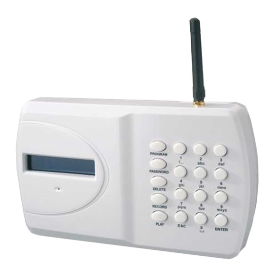
GJD710 GSM COMMUNICATOR
Page
2
3
4-6
7-8
9
10
11
11
11
12
13
network)
Kit Contents:
1 x GJD710 GSM Communicator
1 x Fixing Kit
1 x Installation & Programming
Guide
Current: (12V)
60-70mA STANDBY
100mA-250mA OPERATING
OPERATING TEMP -20˚c TO +70˚c
Advertisement
Table of Contents

Related Manuals for GJD GJD710

Summary of Contents for GJD GJD710
- Page 1 Turn on/off Communicator via Keypad, text or dial-in plus password Manual Contents: Page Kit Contents: Communicator Fit Installation Instructions 1 x GJD710 GSM Communicator Connections on the Communicator 1 x Fixing Kit Essential Programming 1 x Installation & Programming Advanced Programming...
- Page 2 COMMUNICATOR FIT INSTALLATION INSTRUCTIONS Tools Required Small cross-head screwdriver Large cross-head screwdriver No. 6 masonry drill bit Hammer drill Small hammer Pencil, ruler and spirit level IMPORTANT: Before you install the Communicator please take into consideration: Check for hidden wire and pipework before drilling holes Keep the Communicator out of reach of small children HOW TO INSTALL THE GSM COMMUNICATOR Remove the screw from the SIM card cover on the rear of the unit and keep safe.
- Page 3 CONNECTIONS ON THE COMMUNICATOR The Trigger terminals are for connection to a switched negative output of an Alarm System’s Bell or Siren (Fig 1 below). If such switched negative triggers are not available, connect the trigger inputs to a N.O. (normally open) relay output with the relay common to OV (Fig 2).
- Page 4 ESSENTIAL PROGRAMMING All Programming must be done when the Communicator is in the “OFF” position (1234 ESC). HOW TO RECORD THE VOICE MESSAGES: Quick guide: Press 1 2 3 4 > RECORD > 1 > ENTER, Record message now (Note: 1 = message for Trigger 1; 2 = message for Trigger 2, etc; 0 = Test Message, if required.) 1.
- Page 5 4. You will see numbers 123456789 illuminated in the Display. This indicates that all 9 telephone numbers (or as many as have been programmed into the Communicator) will be called or sent an SMS on that Trigger. 5. Press 1 – 9 to de-select that phone number from being dialled. You will now see a blank “ - “ where that number was previously.
- Page 6 Display will show Voice or SMS 1 Voice Press 0 to select that telephone number to receive an SMS only or Press 2 to select that telephone number to receive an SMS and Voice message. Press 1 to return to the input sending a Voice message only. Press ENTER to save selection.
- Page 7 Display will show Call Forwarding No call Forwarding Press 1 to select Call Forwarding or 0 to return to No Call Forwarding. Display will show Call Forwarding Forwarding Press ENTER to save your selection. ADVANCED PROGRAMMING HOW TO PROGRAM THE COMMUNICATOR TO GIVE A LOCAL AUDIBLE ALARM AS WELL AS SENDING A VOICE MESSAGE: (Factory Default –...
- Page 8 Display will show Exit Delay Instant Press 3 to change to 30 seconds, Press 6 to change to 60 seconds, Press 0 to return to instant. Press ENTER to save your selection. HOW TO SET THE ARM DELAY SOUND: (Factory Default – Silent.) Select whether you want a silent or audible sound on any arm delay.
- Page 9 1. Key in the four digit user Password code (Factory Default 1234). 2. Press PROGRAM > 8 > ENTER > 2 > ENTER Display will show Output Type Press 1 to program Output 1, Press 2 to program Output 2, etc. Display will show Output Type User Press 1 to select Output as activating on Trigger 1 (if selected, Output 1 will then activate on activation of...
- Page 10 How to turn the Communicator OFF: or to stop it dialling out. From the Communicator: Press 1 2 3 4 ESC – Communicator will show OFF on the display. This will also stop calls being sent out after it has been triggered. From a Telephone: Quick guide: Call the Communicator and press 1 2 3 4 >...
- Page 11 Factory Default Setting. HOW TO TURN THE OUTPUTS ON AND OFF The GJD710 has 4 Outputs that can be programmed: User only (default setting) or Event Follower + User . “Event Follower” means Output 1 activates when trigger 1 is activated, Output 2 when trigger 2 is activated, and so on.
-
Page 12: Other Useful Information
From a telephone: Quick Guide: Call the Communicator and press 1 2 3 4 > 5 Check that the Voice Test Call message and at least one phone number has been programmed into the Communicator. Check whether you wish all or some programmed telephone numbers to receive such Voice Test Call message (default is all numbers). -
Page 13: Trouble Shooting
TROUBLE SHOOTING I have connected the Communicator to an Alarm Panel. The panel has activated, but there is no message appearing on the Communicator’s LCD display and it is not dialling out. Check the following carefully: Does the Communicator have a 12V supply – either from the panel or via a 500ma 12V mains adaptor? Does the Communicator have a SIM card fitted? The words “On GSM Ready”... - Page 14 NOTES...
Need help?
Do you have a question about the GJD710 and is the answer not in the manual?
Questions and answers