
Subscribe to Our Youtube Channel
Related Manuals for Ultrak KC5500CN

Summary of Contents for Ultrak KC5500CN
- Page 1 KC5500CN / KC550BCN KC7500CN 1/3" DSP COLOR CAMERA INSTALLATION INSTRUCTIONS Ultrak Worldwide Support Center: 1301 Waters Ridge Drive Lewisville, TX 75057 (800) 796-2288 (972) 353-6400 FAX (972) 353-6670 ®...
- Page 2 (972) 353-6400 ALL RIGHTS RESERVED. NO PART OF THIS PUBLICATION MAY BE REPRODUCED BY ANY MEANS WITHOUT WRITTEN PERMISSION FROM ULTRAK. THE INFORMATION IN THIS PUBLICATION IS BELIEVED TO BE ACCURATE IN ALL RESPECTS. HOWEVER, ULTRAK CANNOT ASSUME RESPONSIBILITY FOR ANY CONSEQUENCES RESULTING FROM THE USE THEREOF.
- Page 3 USERS OF THE PRODUCT ARE RESPONSIBLE FOR CHECKING AND COMPLYING WITH ALL FEDERAL, STATE, AND LOCAL LAWS STATUTES CONCERNING MONITORING RECORDING OF VIDEO AND AUDIO SIGNALS. ULTRAK SHALL NOT BE HELD RESPONSIBLE FOR THE USE OF THIS PRODUCT IN VIOLATION OF CURRENT LAWS AND STATUTES.
- Page 4 IMPORTANT SAFEGUARDS READ INSTRUCTIONS -- All the safety and operating HEED WARNINGS -- Follow all instructions marked on the instructions should be read before the appliance is operated. video monitor or equipment. RETAIN INSTRUCTIONS -- The safety and operating LIGHTNING -- For added protection for video monitor or instructions should be retained for future reference.
- Page 5 FCC COMPLIANCE STATEMENT INFORMATION TO THE USER: THIS EQUIPMENT HAS BEEN TESTED AND FOUND TO COMPLY WITH THE LIMITS FOR A CLASS B DIGITAL DEVICE, PURSUANT TO PART 15 OF THE FCC RULES. THESE LIMITS ARE DESIGNED TO PROVIDE REASONABLE PROTECTION AGAINST HARNFUL INTERFERENCE IN A RESIDENTIAL INSTALLATION.
- Page 6 THIS PAGE INTENTIONALLY LEFT BLANK.
-
Page 7: Table Of Contents
ABOUT THE 1/3” DSP COLOR CAMERA....1 PURPOSE............1 FEATURES ............1 SECTION 2 CAMERA CONTROLS AND CONNECTIONS ..3 KC5500CN/KC5500BCN........3 2.1.1 KC5500CN/KC5500BCN Camera Back ..4 2.1.2 KC5500CN/KC5500BCN Camera Front..5 2.1.3 KC5500CN/KC5500BCN Camera Top..5 2.1.4 KC5500CN/KC5500BCN Camera Bottom... 6 KC7500CN ............ - Page 8 THIS PAGE INTENTIONALLY LEFT BLANK. viii...
-
Page 9: About The 1/3" Dsp Color Camera
PURPOSE The 1/3" DSP color security camera provides SONY, true-color images especially for closed-circuit television (CCTV) and security surveillance applications. FEATURES The features of the KC5500CN, KC550BCN, and KC7500CN cameras include: • High-performance 1/3" SONY DSP color CCD technology •... - Page 10 THIS PAGE INTENTIONALLY LEFT BLANK.
-
Page 11: Camera Controls And Connections
SECTION 2 CAMERA CONTROLS AND CONNECTIONS KC5500CN & KC550BCN FRONT VIEW BACK VIEW VIDEO OUT SHUTTER 12VDC/24VAC CLASS 2 2 3 4 TOP VIEW BOTTOM VIEW Continued on next page... -
Page 12: Kc5500Cn/Kc5500Bcn Camera Back
2.1.1 KC5500CN & KC550BCN Camera Back 1. Phase Adjustment – This is used in a multi-camera system when power is supplied from different sources, causing the camera to be out of phase. This situation affects auto-switching of the cameras by causing a vertical flip or roll during the switch interval. -
Page 13: Kc5500Cn/Kc5500Bcn Camera Front
2.1.2 KC5500CN & KC550BCN Camera Front 6. C/CS Backfocus Adjust Ring – Allows the user to adjust the back focal length or picture focus by rotating this ring clockwise for C-mount and counter-clockwise for CS-mount lenses. 7. Backfocus Lock Screw – Allows the user to secure the backfocus setting. -
Page 14: Kc5500Cn/Kc5500Bcn Camera Bottom
2.1.3 KC5500CN & KC550BCN Camera Top, continued A/I Switch – The auto iris switch allows the user • to select the supplied auto-iris control signal for the lens. Position the switch toward the front of the camera to choose DC when the auto-iris control lens requires DC control signal. -
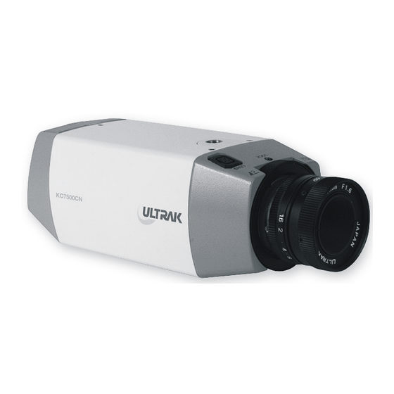
Page 15: Kc7500Cn
KC7500CN FRONT VIEW BACK VIEW VIDEO OUT SHUTTER 12VDC/24VAC CLASS 2 2 3 4 TOP VIEW BOTTOM VIEW Continued on next page... -
Page 16: Kc7500Cn Camera Back
2.2.1 KC7500CN Camera Back 1. Phase Adjustment – This is used in a multi-camera system when power is supplied from different sources, causing the camera to be out of phase. This situation affects auto-switching of the cameras by causing a vertical flip or roll during the switch interval. -
Page 17: Kc7500Cn Camera Front
2.2.2 KC7500CN Camera Front 6. Video Out BNC Connector – This BNC connector provides a 1.0 Vp-p/75 Ohms composite video signal. 7. C/CS Backfocus Adjust Ring – Allows the user to adjust the back focal length or picture focus by rotating this ring clockwise for C-mount and counter-clockwise for CS-mount lenses. - Page 18 2.2.4 KC7500CN Camera Top, continued AWB Adjustment – The auto white balance • switch, when set to the AUTO position, allows the camera to automatically aim to maintain white objects as white even if the light color changes. A/I Switch – The auto iris switch allows the user •...
-
Page 19: Kc7500Cn Camera Bottom
2.2.4 KC7500CN Camera Bottom 12. Mounting Bracket Hole – This threaded ¼"-20 hole is used to mount the camera onto a mounting bracket or tripod. - Page 20 THIS PAGE INTENTIONALLY LEFT BLANK.
-
Page 21: Camera Installation And Adjustment
SECTION 3 CAMERA INSTALLATION AND ADJUSTMENT CONTENTS OF PACKAGE Installation of the camera must be performed by qualified service personnel in accordance with all local and national electrical and mechanical codes. Carefully remove the color camera and its accessories from the carton and verify that they were not damaged in shipment. - Page 22 INSTALLATION continued Select a suitable location for the camera. IMPORTANT: Contact your authorized Ultrak dealer/distributor to purchase cable which is available in various lengths according to the application. Use a suitable fastener and necessary tools to mount the camera stand or mounting bracket to a...
- Page 23 Contact your authorized Ultrak dealer/ distributor to purchase longer cables. Plug the cable into the BNC output port labeled VIDEO OUT located on the back of the camera.
- Page 24 BASIC INSTALLATION continued Connect a two-conductor power cable to the 24V ac or 12V dc input port located on the back of the camera. 12V dc/24V ac Class 2 Use a UL-listed Class 2 power transformer and a 24V ac or 12V dc power adapter.
-
Page 25: Manual Iris Lens Adjustment
MANUAL IRIS LENS ADJUSTMENT A manual iris lens is used in indoor applications where lighting from windows can considerably affect the light level of the room. When using the manual iris lens, perform the following: 1. Set the E/I switch to ON. 2. - Page 26 VIDEO-TYPE AUTO-IRIS LENS INSTALLATION AND ADJUSTMENT, continued NAME WIRE COLOR Voltage + Open Video White Ground Black Open Voltage + / Red Video / White Ground / Black Plug the connector into the auto-iris lens jack on the top of the camera. The connector is keyed and can only be inserted into the jack one way.
- Page 27 VIDEO-TYPE AUTO-IRIS LENS INSTALLATION AND ADJUSTMENT, continued For ALC adjustments: To slow the reaction of the lens to changing light, set the range on the AVG setting to average the video level from the camera. Use this when there are bright spots in the picture, such as lights or glare from the sun.
-
Page 28: Dc-Type Auto-Iris Lens Installation And Adjustment
1. Thread the DC-type auto-iris lens onto the lens mount on the front of the camera. 2. If using an Ultrak lens, skip to step 3. If using a non-Ultrak lens, use the manufacturer’s instructions to solder the connector that comes supplied with the camera to the lens control wires. -
Page 29: Backfocus Adjustment
BACKFOCUS ADJUSTMENT Although the camera lens was backfocused by the manufacturer prior to shipping, it may be necessary to make modifications. For best results, perform backfocus adjustments at night or while using a #6 or #8 welder’s glass in front of the lens. -
Page 30: Zoom Lens Backfocus Adjustment
ZOOM LENS BACKFOCUS ADJUSTMENT The objective of backfocusing a zoom lens is similar to that of a fixed focal length camera, except that the backfocus is also adjusted to maintain the focus when “zooming” the lens in and out of a scene. For zoom lens backfocus adjustment, perform the following: Choose an object at the farthest range that you wish... - Page 31 ZOOM LENS BACKFOCUS ADJUSTMENT, continued IMPORTANT: Verify that the camera remains in focus after tightening the lock screw. On occasion, tightening the lock screw can cause the camera to be slightly out of focus. Repeat the previous steps as many times as necessary to maintain a clear picture through the entire zoom range.
- Page 32 THIS PAGE INTENTIONALLY LEFT BLANK.
-
Page 33: Troubleshooting
SECTION 4 TROUBLESHOOTING If problems occur, verify the installation of the camera with the instructions in this manual and with other operating equipment. Isolate the problem to the specific piece of equipment in the system and refer to the equipment manual for further information. PROBLEM CHECK Make sure the system is plugged in. - Page 34 THIS PAGE INTENTIONALLY LEFT BLANK.
-
Page 35: Preventive Maintenance
SECTION 5 PREVENTIVE MAINTENANCE Following the preventive maintenance schedule allows detection and correction of minor faults before they become serious and cause equipment failure. Every three months, perform the following: Inspect all connecting cables for deterioration or other damage. Clean components with a clean damp cloth. Verify that all mounting hardware is secure. -
Page 36: Specifications
Image Sensor: 1/3" Interline transfer CCD Video Format: NTSC, 525 lines Horizontal Frequency: 15.75 KHz Vertical Frequency: 60 Hz Resolution: KC5500CN & KC550BCN: 330 TV lines KC7500CN: 470 TV lines Signal/Noise Ratio: 46dB (AGC off) Minimum Illumination: 1.0 Lux (F1.4) Video Output: 1.0 Vp-p, 75 Ohms,...
Need help?
Do you have a question about the KC5500CN and is the answer not in the manual?
Questions and answers