Mackie M800 Service Manual
Fr series
Hide thumbs
Also See for M800:
- Owner's manual and warranty registration (27 pages) ,
- Hook-up manual (4 pages) ,
- Brochure (8 pages)
Table of Contents
Advertisement
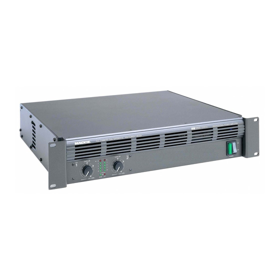
M800
FR series power amplifier
FULL SYMMETRY DUAL DIFFERENTIAL HIGH CURRENT DESIGN
CH
GAIN/dB
GAIN/dB
1
SIG
OL
OL
3v
3v
18
18
–
–
16
20
3
3
16
20
2v
2v
–
–
14
22
6
6
14
22
–
–
12
24
9
9
12
24
–
–
20
20
6
26
6
26
CH STATUS
28
28
1v
1&2
1v
1.23v (+4dBu)
1.23v (+4dBu)
SENSITIVITY
NORM
HOT
SENSITIVITY
(MONO BRIDGE)
800 WATTS
4 OHM LOAD MIN.
400 WATTS CH
2 OHMS LOAD MIN.
MONO
BRIDGE
1
CHANNEL
CH
CH
1
2
INPUT
+
+
–
–
BAL/UNBAL
SPEAKER OUTPUTS
SERVICE MANUAL
Page 3 is interactive
CH
2
120 VAC 60 Hz
1500 WATTS
LOW CUT
CONSTANT DIRECTIVITY
FILTER
HORN EQ /AIR EQ
AMP MODE
TYPICAL
35 Hz
STAGE
4.5k Hz
MONITOR
100 Hz
OFF ON
STEREO
MONO
OFF
170 Hz
2k Hz
6k Hz
AIR EQ
TYPICAL
TYPICAL
THRU
PROFESSIONAL POWER AMPLIFIER
POWER
CAUTION
WARNING:
SERIAL NUMBER
TO REDUCE THE RISK OF FIRE OR ELECTRIC SHOCK, DO NOT
EXPOSE THIS EQUIPMENT TO RAIN OR MOISTURE. DO NOT REMOVE COVER.
RISK OF ELECTRIC SHOCK
NO USER SERVICEABLE PARTS INSIDE. REFER SERVICING TO QUALIFIED PERSONNEL.
DO NOT OPEN
AVIS:
RISQUE DE CHOC ELECTRIQUE — NE PAS OUVRIR
CONCEIVED, DESIGNED, AND MANUFACTURED BY MACKIE DESIGNS INC • WOODINVILLE
WA • 98072 • USA • MADE IN USA • PATENTS PENDING • COPYRIGHT ©1999
THE FOLLOWING ARE TRADEMARKS/REGISTERED TRADEMARKS OF MACKIE DESIGN INC.: "MACKIE" , "FR SERIES" , & THE "RUNNING MAN" FIGURE
CONSTANT DIRECTIVITY
LOW CUT
LIMITER
HORN EQ /AIR EQ
FILTER
TYPICAL
35 Hz
STAGE
4.5k Hz
MONITOR
OFF ON
OFF ON
100 Hz
2k Hz
6k Hz
OFF
170 Hz
AIR EQ
TYPICAL
TYPICAL
THRU
©1999,©2000 MACKIE DESIGNS, INC.
ON
OFF
MANUFACTURING DATE
2
CHANNEL
INPUT
BAL/UNBAL
820-215-00
Advertisement
Table of Contents

Subscribe to Our Youtube Channel
Related Manuals for Mackie M800


Summary of Contents for Mackie M800
-
Page 1: Service Manual
CONCEIVED, DESIGNED, AND MANUFACTURED BY MACKIE DESIGNS INC • WOODINVILLE WA • 98072 • USA • MADE IN USA • PATENTS PENDING • COPYRIGHT ©1999 THE FOLLOWING ARE TRADEMARKS/REGISTERED TRADEMARKS OF MACKIE DESIGN INC.: "MACKIE" , "FR SERIES" , & THE "RUNNING MAN" FIGURE MONO... - Page 2 SERVICE ON THIS EQUIPMENT IS TO BE PERFORMED BY EXPERIENCED REPAIR TECHNICIANS ONLY...
-
Page 3: Table Of Contents
Mackie Designs, Service Technical Assistance, is available 8AM - 5PM PST, Monday through Friday for Authorized Mackie Service Centers, at 1-800-258-6883. Feel free to call with any questions and speak with a carefully-calibrated technician. If one is not available, leave a detailed message and a qualified Mackoid will return your call asap. -
Page 5: Specifications
Specifications Maximum Power, mid band: Distortion: Transient Recovery: 175 watts per channel into 8 Ω SMPTE IMD, TIM (250mW to rated < 1µs for 20 dB overdrive @ 1kHz 275 watts per channel into 4 Ω < 0.025% @ 8 Ω power) 400 watts per channel into 2 Ω... - Page 6 specifications continued. Owner’s manual addendum Power Consumption: 55 watts at idle NOTE: The specifications are from the owner’s manual ad- 400 watts with musical pro- dendum, and not from the initial release of the owner’s gram fully loaded manual. Since the owner’s manual was produced, there (4 Ω...
-
Page 7: Connectors
Connectors MAIN BOARD TRANSFORMER SECONDARIES R51 BIAS ADJUST BIAS T.P. BIAS T.P. FUSE F1 Display board +16V -16V SEND(1) AMP-IN (1) SEND(2) RTN(2) OVERTEMP +64V AMP-OUT(1) AMP-OUT(2) -
Page 8: Troubleshooting Tips
Troubleshooting tips - output failures After a catastrophic failure, it is likely that the main supply fuse will be blown. Replace the fuse and very slowly bring up the Variac while monitoring line consumption. It is likely that substantial line current will be pulled due to shorted output parts. Remove the main board from the unit and check for shorted output transistors. -
Page 9: Safety Test
Safety test You must perform the following leakage test before returning the unit to your customer. Take every safety precaution to protect yourself while doing this test. 1. Make a small loading RC circuit as shown in the diagram below, and connect the AC volt meter between the AC power source ground and any exposed metal on the unit under test. -
Page 10: Bias And Test Procedure
Bias and test procedure After the unit has been repaired, the following should be done to assure long term reliable operation. If a distortion analyzer is present, distortion specifications should be verified. 1. Adjusts bias in both channels (R51 & R60) for 30mV +/- 2mV at bias test points (J5 & J6) after unit has idled for a few minutes. -
Page 11: Circuit Theory
Circuit Theory Much of the circuitry in the M•800 is self explanatory from the schematics. This section will explain the unique circuits and architecture. Samples in this section will refer to Channel-1 for circuitry that is identical on both channels. INPUT CIRCUITRY The signal path begins at the 1/4"... - Page 12 The high current gain of the output stage effectively isolates the load from the voltage amplifier. Consequently Mackie can get nice low distortion numbers, with less negative feedback than the competition. Less feedback, and good frequency response, results...
- Page 13 Other amps, of more conventional design, take a finite amount of time to “catch up” before they begin to follow the input signal again. Mackie refers to this phenomenon as “latching”. The “FR-Fast Recovery series” isn’t just marketing buzzwords: It really does result in a more reliable, and better sounding product, with “good”...
- Page 14 fan control continued. The fan speed increases in the following instances: · When the heatsink is above 86°C. Comparator U5B’s output switches low when the heatsink-mounted temperature sensor’s output voltage increases to 860mV (86°C). The output of U5B is coupled to the fan controller via D80. Note: hysteresis for the overtemp detector is supplied by R177 and R179, so that the heatsink temperature must decrease to 61°C (610mV) before the circuit resets and the fan begins to run slow.
-
Page 15: Quick Parts
Quick Parts 1/4" JACK, MONO 400-118-00 QUAD CONNECTOR400-237-00 1/4" JACK, MONO 400-118-00 1/4" JACK, STEREO 400-287-00 IEC SUB ASSY 080-135-00 XLR FEMALE 400-131-00 XLR MALE 400-175-00 POT 130-073-00, KNOB 760-110-00 POT 130-072-00, KNOB 760-110-00 ALL SWITCHES 500-042-00 POT 130-072-00, KNOB 760-110-00 POT 130-073-00, KNOB 760-110-00 XLR MALE 400-175-00 XLR FEMALE 400-131-00... - Page 17 M800 PARTS LIST PART# DESCRIPTION PAGES Parts Numbering guide 040- Cables 090-107-00 Master Parts 055- Finished PCB Assy 080-105-00 Heatsink subassembly 100- Pots and resistors 200- Capacitors 055-212-00 Main Board 300- Semiconductors 400- Jacks/Connectors 055-218-00 Display Board 500- Switches 510- Fuses...
- Page 18 SW RCKR ILLUMINATED 550-249-00 PLATE XFMR .335IDX4.528OD 550-380-00 SCR CHASSIS M800 AMP 550-381-00 PNT LEFT SIDE M800 550-382-00 PNT TOP COVER M800 AMP 550-560-00 PNT RT SIDE M800 550-562-00 BRKT PLENUM M800 551-029-50 EXTR SCRN DSPLY BZL M800 700-005-00 SEMS 8-32X1/2 PHP BLKZC...
- Page 19 Part # Description Notes 080-139-00 SA XFMR M800 120V/60HZ 120v units 080-139-01 SA XFMR M800 240V/50HZ 240v units 080-139-02 SA XFMR M800 100V/50HZ 100v units 510-028-00 FUSE SB 10A 3AB 1/4X1-1/4 120v units 510-057-00 FUSE SB 3AG 5AMP 230v units...
- Page 20 212c 055-212-00 Rev C Main pcb assembly PART NO. DESCRIPTION VALUE REFERENCE DESIGNATORS 040-295-00 WIRE 18AWG WHT TERM/QD J1 J3 040-296-00 WIRE 18AWG RED TERM/QD 040-297-00 WIRE 18AWG BLK TERM/QD 040-347-00 CABLE ASSY, 18AWG, GN/YW, 6 100-017-00 RESISTOR CF R183-184 110-060-00 RES CF .25W 5% 3K OHM R27-28 R36-37 R69-70 R73-74...
- Page 21 212c PART NO. DESCRIPTION VALUE REFERENCE DESIGNATORS 200-007-02 CAPACITOR MYLAR T&R 0.01 C8 C46 200-015-02 CAPACITOR MYLAR T&R 0.0047 C91 C94 200-023-00 CAPACITOR, POLY BOX .001uF 20% C89 C97 200-024-00 CAPACITOR, POLY BOX .01uF 200-025-02 CAPACITOR MYLAR T&R 0.56 C90 C100-101 C114 200-027-02 PLY .1UF 5% 100V TR C30-31 C35-36 C40-45...
- Page 22 400-287-00 CONNECTOR JACK 1/4 RTA STEREO PC MOUNT J37-38 450-212-00 PCB, MAIN, M-800 Z304 500-042-00 SWITCH, SLIDE 4P3T SW1-4 550-392-00 SHIELD, GROUND M800 601-006-00 INDUCTOR, AIR CORE L5-6 601-008-00 INDUCTOR 10uH L1-4 730-038-00 JET MELT 3M 3779-Q 218a 055-218-00 REV A Display pcb assembly PART NO.
Need help?
Do you have a question about the M800 and is the answer not in the manual?
Questions and answers