Table of Contents
Advertisement
ASR Audiosystems Friedrich Schaefer, D-35727 Herborn, Germany
1.0
1.1
1.2
1.3
1.4
2.0
2.1
2.1.1
2.1.2
2.1.3
2.1.4
2.1.5
2.1.6
2.2
2.2.1
2.2.2
2.2.3
2.2.4
2.2.5
3.0
3.1
3.2
3.3
3.4
4.0
4.1
4.2
4.3
5.0
5.1
5.2
Touble-shooting
6.0
6.1
How the separate battery power supply works
6.2
6.3
to the direct input of the ASR Emitter
Connecting the external power supply/supplies
2.2.2.1
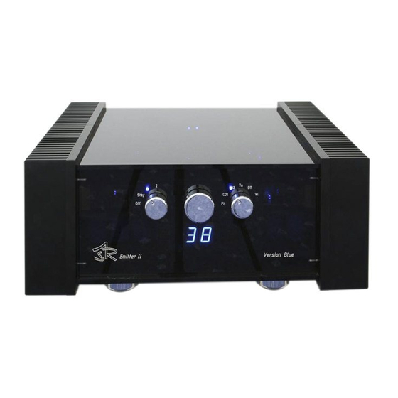
High End Integrated Amplifier ASR Emitter
Page 01
Page 02
Page 03
Page 03
Page 04
Page 05
Page 06
Page 07
Page 08
Page 09
Page 10
Page 11
Page 12
Page 13
Page 14
Page 16
Page 16
Page 17
Page 19
Page 20
Page 1
Advertisement
Table of Contents

Related Manuals for ASR emitter


Summary of Contents for ASR emitter
-
Page 1: Table Of Contents
Page 09 2.2.3 Connecting a headset to the ASR Emitter Page 10 2.2.4 Connecting a second pair of speakers to the ASR Emitter 2.2.5 Connecting the ASR Battery Power Supply (available only for the ASR Emitter Exclusive-versions!) Operating the ASR Emitter... -
Page 2: Receiving The Asr Emitter - First Moves
Unpacking the ASR Emitter Use care in unpacking your ASR Emitter. Inspect it for any shipping damage and call your dealer immediately if any is found. Do not plug your ASR Emitter into an AC outlet if you find shipping damage. -
Page 3: Important Safety Precautions
ASR Audiosystems Friedrich Schaefer, D-35727 Herborn, Germany The heatsinks of the ASR Emitter radiate some heat, so please place the main unit in a place, where air can circulate around the heatsinks. Never put a unit on top of the main unit. -
Page 4: Connecting The Asr Emitter To Your System
20 and 30). If you are not playing the ASR Emitter for more than a week, the same effect will occur, but not as apparent as when connected for the first time. After one or two days of listening the ASR Emitter sounds as good as the unit did before. -
Page 5: Standard Connections
„Ta“ = tape, „CD“ = CD player, „Tu“ = Tuner, „DT“ = digital tape, „Vi“ = vcr. The additional RCA sockets (on the backpanel, outer left/right side) are tape outputs – the ASR Emitter I is equipped with one, the ASR Emitter II with two tape out RCA sockets. These outputs are named „Out“. -
Page 6: Connecting A Tape Deck To The Asr Emitter
Connect the „Line out“ or „Tape Ot“-RCA sockets on your tape deck to the RCA input sockets „Ta“ on the ASR Emitter and the „Line In“- or „Tape In“-RCA sockets on your tape deck to the „Out“-RCA sockets (sockets closest to the heatsinks) on the ASR Emitter. - Page 7 Do not reverse „minus“ (black) and „plus“ (red) – neither on the ASR Emiter nor on your speakers. If the ASR Emitter is equipped with one speaker output, the output relais for A and B are switched together to improve the output resistance. The display on the frontpanel of the ASR Emitter shows „A+B“.
-
Page 8: Additional Connections (On Special Order)
ASR Active Powercord on all the components in your audio system. Additional connections (on special order) Every ASR Emitter can be equipped with a lot of in- and outputs on special order at additional cost. The most common connections are described here. -
Page 9: Adjusting The Asr Plug-In Phonoboard
ASR Audiosystems Friedrich Schaefer, D-35727 Herborn, Germany The ASR plug-in phonoboard can be retrofitted. Simply follow the described steps: before you put the phonoboard into the ASR Emitter, please adjust it acoording to the cartridge you are using (see 2.2.2.1) turn off the ASR Emitter (left control knob to „0“-position) and disconnect the... -
Page 10: Connecting A Headset To The Asr Emitter
Every ASR Emitter I can be equipped with an additional speaker output. The speaker outputs are named „A“ and „B“. Every ASR Emitter II can be equipped with up to two additional speaker outputs. The speaker outputs are named „A“, „B“ and „C“. The additional speaker outputs on the ASR Emitter can be either selected single („A“... -
Page 11: Operating The Asr Emitter
The external power supply/supplies of the ASR Emitter can be operated in an energy saving mode: all the internal voltages of the ASR Emitter are cut in half in this mode. After setting the left knob on the frontpanel from „Standby“- to „1“-position, every ASR Emitter is operating in the energy saving mode for one minute. -
Page 12: Front Panel Control Knobs Of The Asr Emitter
(speaker-)outputs „A“ and „B“ selected to play together, normal operating position If the ASR Emitter is controlled via remote control, the position of the left knob may not exactly correspond with the actual operating mode. The chosen input is indicated by aN LED above the (right) input selector knob. -
Page 13: Operating The Asr Emitter Via Remote Control
Emitter is turned on, pressing the tape monitor switch allows you to listen to the source, that you are recording to the tape unit connected to the „Ta“-input. If the ASR Emitter is in the „Standby“-mode, pressing the tape-monitor switch activates the adjustments for the input level adjust, energy saving mode, balnace and display brightness (refer chapter no. -
Page 14: Adjustments Of The Asr Emitter
„Volume +/--button on the remote control or move the middle knob on the ASR Emitter to the right (+) or left (-). To save your individual adjustments please put the left knob of the ASR Emitter to the „Off“-postion and keep the unit off for at least ten seconds. - Page 15 – the orange „Pegelaus“-LED is flashing. Now either use the „Volume +“- (increases input level) or „Volume -“-button (decreases input level) on the remote control or the middle knob of the ASR Emitter to adjust the input level for the chosen input. For all other inputs do equal.
-
Page 16: Protection Circuits Of The Asr Emitter
If the protection circuits switch the ASR Emitter off, put the left knob to the „Off“- position and press the round „Status“-button on the remote control to cancel the „On“-lock. -
Page 17: Maintenance Of The Asr Emitter
ASR Emitter´s frontplate to the „Off/0“-position and wait a least 20 seconds put the left knob to the „Standby“-postion now you can switch the ASR Emitter on by either putting the left knob to the „1“-postion or by pressing the „On/Off“-button on the remote control 5.2.1... - Page 18 5.3.3 The ASR Emitter is not reacting on signals from the remote control Is the left knob on the frontplate of the ASR Emitter in the „1“- or „2“-postion? please put the knob to the „1“-position. go on with b) Is the Philips remote control set to the „Audio 2“...
-
Page 19: Facts About The Asr Emitter
- the input stage of the ASR Emitter Exclusive now will be supplied with voltage from the batteries again. • the input stage of the ASR Emitter can be continously supplied with voltage from the batteries for about 100 hours. -
Page 20: How The Asr Emitter Works
The negative slave voltage of –10 volts is indicated by a yellow LED. In all other postions of the left knob, the transformers in the separate power supply/supplies is/are switched on to supply the amplifier section of the ASR Emitter – this is indicated by a shining yellow LED in the separate power supply/supplies. - Page 21 ASR Audiosystems Friedrich Schaefer, D-35727 Herborn, Germany shielding, the main unit of the ASR Emitter is made of acrylic glass. RMS output power at 20Hz to 20kHz, 0.1 % distortion, both channels driven: ASR Emitter I Basic 2x 140 watts/8 ohms, 2x 250 watts/4 ohms, 2x 450 watts/2 ohms, 2x 600 watts/1 ohm...
Need help?
Do you have a question about the emitter and is the answer not in the manual?
Questions and answers