Table of Contents
Advertisement
Advertisement
Table of Contents
Troubleshooting

Summary of Contents for Monaco VMOTO
- Page 1 VMOTO MONACO OWNER HANDBOOK...
-
Page 2: Table Of Contents
VMOTO MONACO V1 ..................... 4 GENERAL INFORMATION..................5 Description......................5 Specifications...................... 6 Inspection Tips....................7 Safety Precautions....................7 Torque Settings ....................8 Lubrication Points..................... 10 Trouble Shooting ....................12 2.7.1 Engine Fails to Start:................. 12 2.7.2 Poor spark ....................12 2.7.3... - Page 3 5.3.1 Brake lining assembly (brake shoe, brake shoe spring)......35 Rear Shock Absorber ..................35 ELECTRICAL SYSTEM ..................36 Maintenance & troubleshooting................ 36 6.1.1 Starter System ................... 38 Battery....................... 38 6.2.1 Charging the battery.................. 39 6.2.2 Rectifier..................... 39 6.2.3 Starter Relay....................40 6.2.4 Operation of starter relay.
-
Page 4: Vmoto Monaco V1
1 VMOTO MONACO V1 This Owner Handbook was compiled by Gledhill & Associates and remains the property of Gledhill & Associates. This document may not be copied or distributed without the expressed permission of Gledhill & Associates. While all care has been taken in the compilation of this document, variation in manufacturer’s specification and production values may lead to some differences from... -
Page 5: General Information
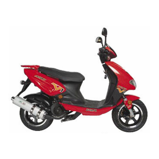
2 GENERAL INFORMATION 2.1 Description... -
Page 6: Specifications
2.2 Specifications Total Length 1920 mm Total Width 705 mm Total Height 1165 mm Wheel Base 1265 mm Ground Clearance 120 mm Weight (dry) 100 Kg Engine Style Single cylinder, 4 stroke, air cooled. Engine Type 153QMI-3 Bore & Stroke 52.4 mm x 57.8 mm Intake Valve Gap (mm) 0.08 –... -
Page 7: Inspection Tips
Battery 12V 7AH Head Lamp (H/L) 12V 35W/35W x1 Rear Lamp 12V 5W x1 Brake Lamp 12V 21W x1 Turn Lamp 12V 10W x4 Suspension Front Telescopic Suspension Rear Rocker Arm Frame Steel Tube 2.3 Inspection Tips 1. Bolts and bolt heads use the International Standard (Metric) measurement system. Use of tools other than those complying with the Metric system may cause damage to the parts. -
Page 8: Torque Settings
The engine cover, cylinder, and exhaust pipe can be at a high temperature after the engine has been running. Wait for the engine to cool before working on it or use protective gloves. 2.5 Torque Settings (Monaco representative figure) Standard Torque Values of Bolts and Nuts Specification Torque (kg-cm) - Page 9 Front Wheel Axle Self-lock Nut 500~600 Brake Disk Hex Bolt 180~280 Brake Clipper Tightening Bolt M8x35 210~250 Speed Meter Cable Nut Front Fork Bearing Tightening Nut M25x1.0 600~650 Rear Wheel Axle Self-lock Nut M16x10 600~900 Rear Brake Connecting Rod Bolt M16x32 50~80 Rear Brake Pin Self-lock Nut...
-
Page 10: Lubrication Points
2.6 Lubrication Points (Monaco representative figure) Chassis Lubrication Area Lubrication Type Inner Side of Acceleration Lever Grease Steering Bearing Grease Speed Meter Gear Grease Front Wheel Axle Bearing Grease Front Wheel Axle Grease Main and Side Stand Axles Grease Rear Wheel Bearing... - Page 11 Engine Lubrication Area Lubrication Type Piston and Piston Rings SAE 10W-40 and API SE,SG Engine Oil Piston Pin Big End of Connecting Rod Rocker Arm Frictional Contact Area Cam Shaft and Chain Cylinder Frictional Area Oil Pump Chain Gears Contact Surface Bearing Operation Area O Rings Seal Lip Area...
-
Page 12: Trouble Shooting
2.7 Trouble Shooting 2.7.1 Engine Fails to Start: Check the following possible causes - No fuel Dirty fuel filter Obstructed fuel pipe Obstructed ventilation tube on the fuel tank Damaged carburettor float needle valve Carburettor float chamber dirty Faulty carburettor float No spark from spark plugs Poor spark from spark plugs Dirty spark plugs... -
Page 13: Poor Idle
Main wiring broken or short circuit Ignition coil broken or short circuit Poor idle 2.7.3 Dirty spark plugs Incorrect spark plug gaps Incorrect ignition timing Dirty air filter Faulty carburettor float needle valve Faulty carburettor choke valve Leaks in the contact of carburettor and inlet tube Obstructed carburettor idle jet Leaking head gasket Severely worn cylinder, piston, piston rings... -
Page 14: Inspection And Adjustment
3 INSPECTION AND ADJUSTMENT 3.1 Regular Maintenance Schedule Explanation: (1) Follow the regular maintenance schedule to ensure the motorcycle’s function and life. (2) I : Inspection (including clean up, lubrication, refill, or replace parts), C: Clean, R: Replace, A: Adjust, T: Tighten (check). 1000 2000 3000... - Page 15 Checking: Stop engine for 2~3 minutes after it is warm. Remove the engine oil gauge and check if the oil level is below the lower limit. Fill engine oil to the level between upper and lower limits. Changing Engine Oil: Note: Change engine oil according to regular maintenance schedule.
-
Page 16: Final Drive Gear Oil
Inspection: (1) If O-ring is damaged, replace with new one. (2) If there is any dirt or foreign objects, clean up before re-assembly. Note: (1) Torque of oil strainer screen: 150 ~ 200 kg-cm. (2) Lubrication Type: SAE 10W-40 Engine oil capacity Engine disassembled : 900c.c. -
Page 17: Brake System
• Oil capacity • Gearbox disassembled : 110 c.c. • Regular Maintenance : 90 c.c. Check if there is any leaking after oil refill. 3.4 Brake System 3.4.1 Front Brake Lever Free Play Note: Front brake lever free play is 10~20 mm. Adjustment: The free play of the front brake lever is not adjustable on this scooter. -
Page 18: Bleed Brake Line
3.4.4 Bleed Brake Line (1) Apply suitable plastic tube on drain plug, and put a tray under drain hole. (2) Slowly apply front brake several times. (3) Hold the front brake lever, and maintain pressure. (4) Loosen the bleeder valve. (5) Tighten the valve, and then release the brake lever. -
Page 19: Inspection Of Brake Lining And Wheel
Adjustment: Adjust the adjustment nut. 3.4.7 Inspection of Brake Lining and Wheel Inspection: Check the wear indicator plate. If the index is higher than the limit, check the wear of wheel rim and brake lining. Disassembly: 2 tightening bolts on exhaust pipe connector. 2 tightening bolts between exhaust pipe and right crankcase. -
Page 20: Tyre And Tyre Pressure
Disassemble the brake shoe and brake shoe spring. Inspection: Measure the brake lining thickness at three points with Vernier callipers (two ends and centre). If badly worn, replace with new one (brake shoe and brake shoe spring). Note: (1) Useable thickness is 2.0 mm. (2) If less than useable thickness, replace with new parts. -
Page 21: Air Filter
Warning: Don’t over-load the motorcycle. Damage to the tyres may occur if the motorcycle is overloaded. 3.6 Air Filter Disassembly: Air filter side cover tightening bolt. Air filter side cover. Filter tightening bolt. Filter. Inspection: Check if filter is dirty or broken. If dirty or broken, replace with a new one. Note: (1) If ridden on dusty roads or in wet conditions, shorten the replacement schedule for the air filter. -
Page 22: Battery
3.7 Battery Disassembly: Foot mat. (If present) Battery box cover. Disconnect the battery negative “-” cable, and then the positive “+” cable. Warning: Do not touch tools with any metal parts of the frame while disconnecting positive “+” cable. A resulting short circuit could cause sparking and damage to the battery. -
Page 23: Fuel Filter
Note: Spark plug specification: CR7HAS (NGK). Spark plug gap: 0.6 ~ 0.7 mm. Warning: Install the spark plug initially by hand, and then tighten it with spark plug wrench. Do not over tighten the spark plug. Note: Torque of spark plug: 100 ~ 120 kg-cm. 3.9 Fuel Filter Inspection: Check if it is hardened, damaged, or leaking. -
Page 24: Throttle Valve
* Adjust Procedure * Measure the engine idle speed with an appropriate gauge. Adjust idle speed to adequate range with phillips head screw driver. Note: (1) Increase engine speed by rotating the screw clockwise. (2) Reduce engine speed by rotating the screw counter-clockwise. (3) Engine idle speed range: 1800±100 rpm. -
Page 25: Carburettor Throttle Cable Play
Note: 1. Increase engine speed by rotating the nut clockwise. 2. Reduce engine speed by rotating the nut counter-clockwise. Tighten adjusting nut after adjustment. Close dust boot. 3.11.2 Carburettor Throttle Cable Play Adjustment Procedure: Note: First, adjust the throttle lever play. If it does not satisfy the specification, then adjust the carburettor throttle play. - Page 26 Disassembly: Loose the air duct tightening ring. Kick start arm tightening bolt. Kick start arm. 8 clutch side cover tightening bolts. Clutch side plate. Gasket. Secure the drive plate, and remove the lock nut and gasket. Drive plate.
-
Page 27: Lubrication
V belt. Inspection: Check if the V belt has cracked, deteriorating. If it is in poor condition, replace it with a new V belt. Note: (1) Check the belt length. Wear limit: 18.0 mm or 8000km (2) Belt specification: BANDO VS BELT 743 20 30 Assembly: Assembly is in reverse order of disassembly procedures. - Page 28 Place a vessel under the engine, remove the sump plug and the oil level gauge. (Note that on some engines the drain is also the oil strainer and is located at the bottom of the sump) After draining the oil, clean the oil level gauge (check the O-ring seal) and fit the drain plug (strainer) again.
-
Page 29: Chassis
4 CHASSIS 4.1 Removal of Cover... -
Page 30: Troubleshooting Chassis Problems
Dismount floor panels following the sequence shown in the list: Helmet Case Rear View Mirror Upper Handle Bar Carrier Cover Bottom Plate Front Leg Shield Right and Left Side Front Mudguard cover Cover Set, Leg Mudguard, Fixed , Shield Front Lower Handlebar Lower Side Leg Cover... -
Page 31: Troubleshooting
5.1.1 Troubleshooting Steering too tight (heavy) 1. The bearing at the top of the steering column too tight. 2. Bearing of the steering column broken. 3. The conical base of the steering bearing damaged. 4. Front fork bent. 5. Front wheel shaft bent. 6. -
Page 32: Front Wheel
1. Dirty brake lining/pads or brake disc. 2. Wheel incorrectly mounted. 3. Deformed brake disc. 4. Clogged brake line. 5. Wear of the brake lining/pads. 6. Damage of the seal of the brake calliper piston. 7. Deteriorated brake fluid. 8. Air in the brake system. 5.2 Front Wheel Place the scooter on the main stand for maintenance. -
Page 33: Inspection Of Wheel Rim
Note: If eccentricity is higher than 0.2mm, replace with new one. Speedometer gear assembly. 5.2.1 Inspection of Wheel Rim Put wheel rim on rotation stand. Rotate the wheel slowly and use dial-gauge to measure eccentricity Note: The transverse eccentricity should be within 3.0 mm 2. -
Page 34: Rear Wheel
Note: Torque of rear wheel axle self-lock nut: 600~ 900 kg-cm. Torque of brake calliper tightening bolt: 210 ~250 kg-cm. Torque of speed meter cable nut: 60kg-cm 5.3 Rear Wheel Place the scooter on the main stand for maintenance. Disassembly: 1. -
Page 35: Brake Lining Assembly (Brake Shoe, Brake Shoe Spring)
5.3.1 Brake lining assembly (brake shoe, brake shoe spring). Inspection: Using Vernier callipers make three measurements (two ends and centre) of the lining thickness. If the lining is less than 2.0 mm, replace the assembly. Warning: Do not get any grease on the brake lining. Disassembly: Loosen the rear brake adjusting nut and remove brake cable. -
Page 36: Electrical System
Upper and lower attaching bolts on rear shock absorber. Shock absorber. Inspection: Check if the shock absorber is worn, scratched, leaking, or bent. Note: Torque of shock absorber upper and lower attaching bolts: 200 ~ 300 kg-cm. 6 ELECTRICAL SYSTEM 6.1 Maintenance &... - Page 37 9. Avoid dropping or causing heavy impact to the C.D.I of the ignition system. 10. Check all electrical connectors for solid contact. 11. Spark plugs of a suitable heat value and gap are to be used (see specifications). Troubleshooting: Battery Recharging System: No voltage: 1.
-
Page 38: Starter System
c. Connection between C.D.I and the high-tension coil. Engine not running smoothly: 1. Defective ignition first circuit: a. Bad contact in circuitry or cable. b. Defective of flywheel magneto. 2. Bad ignition secondary circuit. a. The ignition coil insulation defect causing electric leakage. b. -
Page 39: Charging The Battery
Note: Electrolyte’s specific gravity and charge level comparison table (20 Electrolyte Specific 1.280 1.250 1.220 1.190 1.120 Gravity Charge Level Full ¾ ½ ¼ Totally Charge Charged Charged Charged Discharged 6.2.1 Charging the battery Connect battery and charger terminals positive to positive and negative to negative Warning: Battery releases explosive gas during charging. -
Page 40: Starter Relay
6.2.3 Starter Relay 6.2.4 Operation of starter relay. Place the scooter on the main stand for inspection. Inspection: Turn the main switch to “ON” position and press the starter button. Note: (1) If there is a snap sound, then the function is normal. (2) If there is no snap sound, then the function is abnormal.
Need help?
Do you have a question about the VMOTO and is the answer not in the manual?
Questions and answers