
Summary of Contents for Evinox ModuSat TP 40-10
-
Page 1: Servicing Instructions
ModuSat TP Twin Plate Satellite Heating Unit Installation, Commissioning and Servicing Instructions Evinox Ltd T. +44 (0)1372 722277 E. technical@evinox.co.uk W. www.evinox.co.uk 2551390A... -
Page 2: Table Of Contents
Contents 1 GENERAL INFORMATION……………………………………………………………………………………………… 4 1.1 Warnings…………………………………………………………………………………………………………. 4 1.2 Symbols…………………………………………………………………………………………………………… 4 1.3 Safety Instructions…………………………………………………………………………………………... 4 2 TECHNICAL FEATURES………………………………………………………………………………………………….. 6 2.1 Typical Schematic Principle (All Top Connections……………………………………………… 6 2.2 Connection configurations…………………………………………………………………………….… 7 2.3 Dimensions……………………………………………………………………………………………………... 10 2.4 Technical Features…………………………………………………………………………………………... 14 3 INSTALLATION……………………………………………………………………………………………………………… 15 3.1 Recommended handling procedure…………………………………………………………………. 15 3.2 ModuSat TP positioning…………………………………………………………………………………… 15 3.3 Checks before connecting the ModuSat TP………………………………………………………. ... - Page 3 5.6 Typical Wiring Diagram with 3rd Party Room Stat…………………………………………… 36 6 COMMISSIONING ……………………………………………………………………………………………………….. 37 6.1 Initial Commissioning Procedure……………………………………………………………………… 37 6.2 Apartment Circuit Balancing……………………………………………………………………………. 38 6.3 Use of the commissioning switch…………………………………………………………………….. 39 6.4 Adjustment of TMV…………………………………………………………………………………………. 40 6.5 Pump Start‐up ‐ Wilo PWM Pump……………………………………………………………………. 41 6.6 Warranty………………………………………………………………………………………………………… 42 3 ...
-
Page 4: General Information
Evinox representative. Any modifications or adjustments carried out without EVINOX official authorisation will invalidate the warranty and absolves Evinox from any liability. Evinox has the right to make any changes or modifications to the products without prior notice. Symbols... - Page 5 ModuSat TP – Top Connections 5 ...
-
Page 6: Technical Features
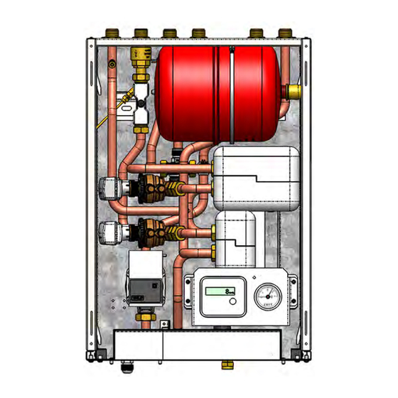
TECHNICAL FEATURES Typical Schematic Principle (All Top Connections) ModuSat TP 40-10, 50-10 & 60-10 Components Primary / DH flow Primary / DH return Domestic cold water Inlet Domestic hot water outlet Secondary / Apartment heating flow Secondary / Apartment heating return... -
Page 7: Connection Configurations
Connection configurations Various connection configurations are available; a few of them are detailed here below. Please contact Evinox for further information. Legend: PF primary flow, PR primary return, SF secondary flow, SR secondary return DR drain, CW cold water, HW domestic hot water TL1 ... - Page 8 TL7 TL8 T1 T2 T3 T4 T5 T6 T7 T1 T2 T3 T4 T5 T6 T7 PF PR HW PF PR CW DR SF SR ...
- Page 9 BL5 BL6 T1 T2 T3 T4 T5 T6 T7 T1 T2 T3 T4 T5 T6 T7 CW HW SF SR CW SF SR PF PR DR PF PR ...
-
Page 10: Dimensions
Note: For clarity, safety drain connections are not shown. Please refer to hydraulic arrangements. Additional connection configurations available as detailed on pages 7-9 of this manual. For specific hydraulic arrangements for other connection configurations please contact the Evinox Technical Department on 01372 722277. - Page 11 Note: For clarity, safety drain connections are not shown. Please refer to hydraulic arrangements. Additional connection configurations available as detailed on pages 7-9 of this manual. For specific hydraulic arrangements for other connection configurations please contact the Evinox Technical Department on 01372 722277.
- Page 12 Note: For clarity, safety drain connections are not shown. Please refer to hydraulic arrangements. Additional connection configurations available as detailed on pages 7-9 of this manual. For specific hydraulic arrangements for other connection configurations please contact the Evinox Technical Department on 01372 722277.
- Page 13 Note: For clarity, safety drain connections are not shown. Please refer to hydraulic arrangements. Additional connection configurations available as detailed on pages 7-9 of this manual. For specific hydraulic arrangements for other connection configurations please contact the Evinox Technical Department on 01372 722277.
-
Page 14: Technical Features
Technical features Electrical MTP 40-10 & 50-10 MTP 60-10 Electric supply 220 / 240 Volt (AC) Frequency 50 Hz Current absorption 0,6 Amps Hydraulic connections Primary circuit supply ¾” ext. thread 1” ext. thread Primary circuit return ¾” ext. thread 1”... -
Page 15: Installation
After removing all packaging, check the unit to ensure that all joints are tight and there is no damage. In cases of damage please contact Evinox immediately. Packaging materials must be properly disposed of in line with current environmental guidelines. - Page 16 All electrical wiring should be installed / checked by qualified personnel in line with current regulations. EVINOX are not liable for damage caused by incorrect electric connections or faulty wiring. The ModuSat should be provided with additional fused protection. This will be via a suitable rated fused switch adjacent to the HIU position.
-
Page 17: Hydraulic Connections
This must be installed in such a way so as to prevent damage or risk of injury to occupants, children or animals. Evinox cannot be held responsible for any damage caused by incorrect installation. The unit must be... -
Page 18: Use Of Pre-Installation Rig
Hang the ModuSat TP Pre-Installation Rig on the bracket. STEP2: Fit the Evinox Flushing Bypass & Valve Kit to the rig and then make final connections to the pipework running to the HIU. -
Page 19: Wall Fixing
Wall fixing The ModuSat TP is designed for wall mounting using brackets to be screwed to the wall as shown below. 42,5 33,5 144,5 144,5 Please note – Weights of the units are shown in the technical table on page 14. 19 ... - Page 20 The wall that the ModuSat is being fixed to must be suitable for bearing the unit weight. Where the wall is not load bearing an optional support frame is available on request. The details of this frame are as follows:- 20 ...
-
Page 21: Pressure Independent Control Valve (Picv) Adjustment
WATER QUALITY MUST 40/50/60‐10 40/50‐10 DHW 60‐10 DHW BE HIGH AND COMPLY PRE- Flow Flow Flow Flow Flow Flow WITH CURRENT BSRIA & CIBSE SETTING GUIDELINES AND EVINOX REQUIREMENTS. 100% 1000 0,278 1500 0.417 2200 0.611 0,250 1350 0,375 1980 0.550 0,222... - Page 22 In the event that the pressure parameters need to be checked during operation, temporary binder points can be installed for testing purposes by an Evinox engineer to ensure they are within the max / min tolerance, the following data can be checked:- For 91L ¾”...
- Page 23 For 93L 1” – ModuSat TP 60-10 DHW P1 = H If P1-P2 > 25 kPa THEN pressure port THE VALVE IS WITHIN THE WORKING RANGE P2 = L pressure port START UP PRESSURE Q≠CONST Q=CONST P1 – P2 25 kPa P1-P2 23 ...
-
Page 24: Primary And Secondary Circuit
During the final fill and treatment the systems must be fully vented to remove all air, and the system pressure adjusted to design requirements (that form part of the design criteria and specification). If the tender specification does not enforce a particular standard then Evinox requirements would be the BSRIA AG 1/2001.1 standard. 24 ... -
Page 25: Precautions
PREVENT/INHIBIT CORROSION. Please note: If the completed installation includes boiler plant supplied by Evinox, then only BIONIBAL, which is approved by Evinox, should be used in the primary and secondary circuits. Our technical personnel, who will visit the project during the course of the installation and at its completion to arrange for its final commissioning and calibration, do so to assist the contractor and install team. -
Page 26: Bionibal
IT IS ADVISABLE to ADD a suitable approved corrosion inhibitor before the system is put in operation. Bionibal dosage and use (If used & when required if Evinox boiler plant is installed) NEW INSTALLATIONS: Fill the circuit with water and check for leaks... -
Page 27: Flushing Bypass
4.5 Flushing Bypass Unit bypassed Flushing bypass Isolation valves are closed (Handles in horizontal position) and bypass is open. Turn screw in horizontal position for flushing of primary system. Unit in normal operation (Open to primary system) Isolation valves are opened (Handles in vertical position) and bypass valve is closed with screw in vertical position. -
Page 28: Electric Connections
The unit is not protected from lightning. Auxiliary connections Don’t connect the Evinox room controller unit to a mains supply as this will cause permanent damage. Use the relevant terminal connections and a suitable 4 wire shielded cable (4 x 0.35mm²) for this connection and follow the procedure on the following page... -
Page 29: Modusat Wiring Connections
Modusat Wiring Connections The modusat wiring board is located within the modusat itself under a removable metal cover. To access the wiring board the full front case cover should be removed. The connections board will be to your left as shown, to take off the cover the retaining screw should be removed and the cover lifted off. - Page 30 Guides for the various connection applications and requirements are detailed in the wiring principle drawings shown on pages 34-36. Evinox strongly recommend in accordance with best practice that all wiring connections to the board, especially the BUS and room controller are terminated using ‘bootlace ferrule’...
-
Page 31: Modusat Connection Board (Visible Once The Cover Is Removed)
5.2 ModuSat Connection Board (Visible once the cover is removed) Please Note: When connecting external valves or pumps to the control board of the ModuSat it must be ensured that each connection does not exceed 1amp @ 220/240V (AC). 31 ... -
Page 32: Room Controller Connections
Room controller connections The Room controller is a white ABS box with a graphic display. It should be installed in the main living area of the dwelling. It must be connected to the control wiring board within the ModuSat (please refer to the electrical diagram) using a 4x0.35 mm2 screened cable. - Page 33 Once the tab has been Connection terminal with released the cover can be room controller hinged up to access connection 4 x 0.35 sqmm + sheild 33 ...
-
Page 34: Typical Modusat Electric Wiring Diagram (Single Room Controller)
Typical ModuSat Electric Wiring Diagram (Single Room Controller) 34 Note 3: Pumps & valves must have localized power supply. Switched neutral connection to be fitted with 1 amp in-line fuse on neutral cable. -
Page 35: Typical Modusat Electric Wiring Diagram With 2 Zone Control
Typical ModuSat Electric Wiring Diagram with 2 Zone Control (2 Room Controllers) 35 Note 3: Pumps & valves must have localized power supply. Switched neutral connection to be fitted with 1 amp in-line fuse on neutral cable. -
Page 36: Typical Wiring Diagram With 3Rd Party Room Stat
Typical Wiring Diagram with 3 Party Room Stat Note 3: Pumps & valves must have localized power supply. Switched neutral connection to be fitted with 1 amp in-line fuse on neutral cable. 36 ... -
Page 37: Commissioning
This prevents the components being exposed to excessive hydraulic shock. If there is a problem with any of the above listed checks, contact Evinox immediately and DO NOT OPERATE THE UNIT until rectified. -
Page 38: Apartment Circuit Balancing
The unit will then require full commissioning by an Evinox engineer. During the commissioning procedure the unit will be fully set up to the system design parameters. All commissioning must be booked well in advance and will be carried out to a pre-agreed programme. -
Page 39: Use Of The Commissioning Switch
45 mins. Please note: The rocker switch above the commissioning push button is the Pump Manual Override. This should NOT be operated or used by persons other than Evinox Engineers as it is for emergency use only. 39 ... -
Page 40: Adjustment Of Tmv
Adjustment of TMV The ModuSat unit is fitted with an internal blending valve on the DHW outlet from the integral storage tank. This enables the DHW storage temperature to be higher to improve DHW recovery and draw off rates but also ensure that the DHW to outlets does not exceed the design / safe temperatures as an additional fail safe protection. -
Page 41: Pump Start-Up - Wilo Pwm Pump
Pump Start-up - Wilo PWM Pump The Wilo Pulse-width modulation (PWM) pump features dry running protection to eliminate burn out and provides compliance with the 2015 pump efficiency regulations. Description of the pump The pump consists of a hydraulic system, a glandless pump motor with a permanent magnet rotor, and an electronic control module with an integrated frequency converter. -
Page 42: Warranty
5 years for the stainless steel heat exchangers 2 years for parts and labour * (Where Evinox do not carry out the commissioning or have a developer agreement in place the two year warranty will cover parts with no... - Page 43 Replacement parts are chargeable until passed as faulty by Evinox, when a credit will be provided. Any parts that have failed as a result of poor servicing or misuse will not be covered by our warranty.
- Page 44 Note: in a constant preoccupation with an improvement of our materials, any modification considered to be useful by our engineering departments and commercial can intervene without notice. * See full terms and conditions of warranty 44 ...
- Page 45 Evinox reserves the right to make changes and improvements which may necessitate alteration to the specification without prior notice. Evinox Ltd T. +44 (0)1372 722277 E. technical@evinox.co.uk W. www.evinox.co.uk 2551390A...
Need help?
Do you have a question about the ModuSat TP 40-10 and is the answer not in the manual?
Questions and answers