Advertisement
Table of Contents
- 1 Table of Contents
- 2 Information
- 3 Component
- 4 Controls
- 5 Choke Lever
- 6 Check before Operation
- 7 Operation
- 8 Throttle Lever
- 9 Maintenance
- 10 Storage/ Transporting
- 11 8. . . . Troubleshooting
- 12 Technical & Consumer Information
- 13 Specifications
- 14 Engine Type with Oil Alert and Without Electric Starting
- 15 Operation
- Download this manual
Advertisement
Table of Contents

Related Manuals for LONCIN 25ZB21-1.2Q


Summary of Contents for LONCIN 25ZB21-1.2Q
- Page 1 Menu...
- Page 2 Thank you for purchasing a water pump. This manual covers the operation and maintenance of water pump: 25ZB21-1.2Q。 The information and specifications included in this publication were in effect at the time of approval for printing. General-purpose Engine Co., Ltd. Reserves the right to make changes at any time without notice and without incurring any obligation.
-
Page 3: Table Of Contents
CONTENTS 1.INFORMATION ……………………………………………………………………………2 2. COMPONENT …………………………………………………………………………… 6 3. CONTROLS ……………………………………………………………………………7 4. CHECK BEFORE OPERATION …………………………………………………………9 5. OPERATION ……………………………………………………………………………10 6. MAINTENANCE ……………………………………………………………………………14 7. STORAGE/ TRANSPORTING …………………………………………………………23 8. . . . TROUBLESHOOTING …………………………………………………………………26 9. TECHNICAL & CONSUMER INFORMATION ………………………………………27 10. SPECIFICATIONS ………………………………………………………………………29 11. -
Page 4: Information
This manual should be considered a permanent part of the pump and should remain with the pump if it is resold. The illustrations in this manual are based in: 25ZB21-1.2Q The illustration may vary according to the type. Keep this owner's manual handy, so you can refer to it at any time. - Page 5 Your safety and the safety of others are very important. And using this water pump safely is an important responsibility. To help you make informed decisions about safety, we have provided operating procedures and other information on labels and in this manual.
- Page 6 IMPORTANT SAFETY INFORMATION This water pump is designed to pump only water that is not intended for human consumption, and other uses can result in injury to the operator or damage to the pump and other property. Always make a pre-operation inspection before you start the engine. You may prevent an accident or equipment damage.
- Page 7 Make sure that any spilled fuel has been wiped up before starting the engine. After refueling, make sure the tank cap closed properly and securely. Hot Exhaust The muffler becomes very hot during operation and remains hot for a while after stopping the engine. Be careful not to touch the muffler while it is hot.
-
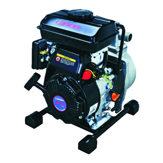
Page 8: Component
2. COMPONENT... -
Page 9: Controls
3. CONTROLS Fuel Valve Lever The fuel valve opens and closes the passage between the fuel tank and the carburetor. The fuel valve lever must be in the ON position for the engine to run. When the engine is not in use, leave the fuel valve lever in the OFF position to prevent carburetor flooding and to reduce the possibility of fuel leakage. -
Page 10: Choke Lever
ENGINE SWITCH Choke Lever The choke lever opens and closes the choke valve in the carburetor. The CLOSE position enriches the fuel mixture for starting a cold engine. The OPEN position provides the correct fuel mixture for operation after starting, and for restarting a warm engine. -
Page 11: Check Before Operation
4. CHECK BEFORE OPERATION IS YOUR ENGINE READY TO GO? For your safety, and to maximize the service life of your equipment, it is very important to take a few moments before you operate the engine to check its condition. Be sure to take care of any problem you find, or have your servicing dealer correct it, before you operate the engine. -
Page 12: Operation
5. OPERATION SAFE OPERATING PRECAUTIONS Before operating the engine for the first time, please review the IMPORTANT SAFETY INFORMATION and the chapter titled BEFORE OPERATION. Carbon monoxide gas is toxic. Breathing it can cause unconsciousness and even kill you. Avoid any areas or actions that expose you to carbon monoxide. -
Page 13: Throttle Lever
CHOKE LEVER 3. Move the throttle lever away from the SLOW position, about 1/3 of the way toward the FAST position. Some engine applications use a remotely-mounted throttle control rather than the engine-mounted throttle lever shown here. LOW SPEED HIGH SPEED THROTTLE LEVER 4. - Page 14 6. If the choke lever has been moved to the CLOSE position to start the engine, gradually move it to the OPEN position as the engine warms up. STOPPING THE ENGINE To stop the engine in an emergency, simply turn the engine switch to the OFF position. Under normal conditions, use the following procedure.
- Page 15 2. Turn the engine switch to the OFF position. 3. Turn the fuel valve lever to the OFF position. SETTING ENGINE SPEED Position the throttle lever for the desired engine speed. Some engine applications use a remotely-mounted throttle control rather than the engine-mounted throttle lever shown here.
-
Page 16: Maintenance
6. MAINTENANCE THE IMPORTANCE OF MAINTENANCE Good maintenance is essential for safe, economical, and trouble-free operation. It will also help reduce air pollution. Improperly maintaining this engine, or failure to correct a problem before operation, can cause a malfunction in which you can be seriously hurt or killed. - Page 17 Make sure the engine is off before you begin any maintenance or repairs. This will eliminate several potential hazards: Carbon monoxide poisoning from engine exhaust. Be sure there is adequate ventilation whenever you operate the engine. Burns from hot parts. Let the engine and exhaust system cool before touching.
- Page 18 (1)Service more frequently when used in dusty areas. (2)These items should be serviced by your servicing dealer unless you have the proper tools and are mechanically proficient. Refer to manual for service procedures. REFUELING Fuel tank capacities 152F: 0.47 US qt (1.4L) With the engine stopped, remove the fuel tank cap and check the fuel level.
- Page 19 FUEL RECOMMENDATIONS Use unleaded gasoline with a pump octane rating of 86 or higher. These engines are certified to operate on unleaded gasoline. Unleaded gasoline produces fewer engine and spark plug deposits and extends exhaust system life. Never use stale or contaminated gasoline or an oil/gasoline mixture. Avoid getting dirt or water in the fuel tank.
- Page 20 3. If the oil level is low, fill to the edge of the oil filler hole with the recommended oil. 4. Screw in the filler cap/dipstick securely. Running the engine with a low oil level can cause engine damage. The Oil Alert system (applicable engine types) will automatically stop the engine before the oil level falls below safe limit.
- Page 21 4. Screw in the filler cap/dipstick securely. OIL FILLER CAP/ DIPSTICK SEALING DRAIN WASHER BOLT SERVICING YOUR ENGINE ENGINE OIL RECOMMENDATIONS Oil is a major factor affecting performance and service life. Use 4-stroke automotive detergent oil. SAE 10W-30 is recommended for general use. Other viscosities shown in the chart may be used when the average temperature in your area is within the recommended range.
- Page 22 AIR FILTER INSPECTION Remove the air cleaner cover and inspect the filter. Clean or replace dirty filter elements. Always replace damaged filter elements. If equipped with an oil-bath air cleaner, also check the oil level. ELEMENT WING NUT AIR CLEANER COVER AIR CLEANER SERVICE A dirty air filter will restrict air flow to the carburetor, reducing engine performance.
- Page 23 SPARK PLUG SERVICE Recommended spark plugs: E5T or other equivalents. An incorrect spark plug can cause engine damage. 1. Disconnect the spark plug cap, and remove any dirt from around the spark plug area. 2. Remove the spark plug with a spark plug wrench. 3.
- Page 24 7. Attach the spark plug cap. IDLE SPEED ADJUSTMENT 1. Start the engine outdoors, and allow it to warm up to operating temperature. 2. Move the throttle lever to its slowest position. 3. Turn the throttle stop screw to obtain the standard idle speed. Standard idle speed: 2,200 ±...
-
Page 25: Storage/ Transporting
7. STORAGE/ TRANSPORTING STORING YOUR ENGINE Storage Preparation Proper storage preparation is essential for keeping your engine trouble free and looking good. The following steps will help to keep rust and corrosion from impairing your engine’s function and appearance, and will make the engine easier to start after storage. Cleaning If the engine has been running, allow it to cool for at least half an hour before cleaning. - Page 26 ADDING A FUEL STABILIZER TO EXTEND FUEL STORAGE LIFE When adding a fuel stabilizer, fill the fuel tank with fresh gasoline. If only partially filled, air in the tank will promote fuel deterioration during storage. If you keep a container of gasoline for refueling, be sure that it contains only fresh gasoline.
- Page 27 4. Pull the starter rope several times to distribute the oil in the cylinder. 5. Reinstall the spark plugs. 6. Pull the starter rope slowly until resistance is felt. This will close the valves so moisture cannot enter the engine cylinder. Return the starter rope gently. If your engine will be stored with gasoline in the fuel tank and carburetor, it is important to reduce the hazard of gasoline vapor ignition.
-
Page 28: 8. . . . Troubleshooting
8. . . . TROUBLESHOOTING ENGINE WILL NOT Possible Cause Correction START 12 Electric starting: Battery discharged. Recharge battery. check battery Fuel valve OFF. Move lever to ON. Move lever to CLOSE Check control Choke OPEN. unless engine is warm. positions Turn engine switch to Engine switch OFF. -
Page 29: Technical & Consumer Information
9. TECHNICAL & CONSUMER INFORMATION TECHNICAL INFORMATION Serial Number Location ENGINE TYPE SERIAL NUMBER Record the engine serial number in the space below. You will need this serial number when ordering parts, and when making technical or warranty inquires. Engine serial number: Carburetor Modification for High Altitude Operation At high altitude, the standard carburetor air-fuel mixture will be too rich. - Page 30 Engine Tune-up ITEM SPECIFICATION 0.028-0.031 in Spark plug gap (0.70-0.80 mm) IN: 0.10 ± 0.02 mm (cold) Valve clearance EX: 0.15 ± 0.02 mm (cold) Other specifications No other adjustments needed CONSUMER INFORMATION Publications These publications will give you additional information for maintaining and repairing your engine.
-
Page 31: Specifications
Recoil start Rotation Anti-clockwise(from P.T.O. side) Spark Plug Clearance (mm) 0.7~0.8mm Igniting Mode Transistorized magneto Ignition Air Cleaner Semi-dry Item Type 25ZB21-1.2Q 25ZB36-1.2Q Length(mm) Width(mm) High(mm) Weight(Kg) Suction Port Diameter 25 mm 25 mm Discharge Port Diameter 25 mm 25 mm Max. -
Page 32: Engine Type With Oil Alert And Without Electric Starting
11. Engine Type with Oil Alert and Without Electric Starting BLACK YELLOW... -
Page 33: Operation
12 .OPERATION SAFE OPERATING PRECAUTIONS To safely realize the full potential of this pump, you need a complete understanding of its operation and a certain amount of practice with its controls. Before operating the pump for the first time, please review the IMPORTANT SAFETY INFORMATION on page 9 and the chapter titled CHECK BEFORE OPERATION. - Page 34 Do not use a hose smaller than the pump’s suction port size. Minimum hose size: 25ZB21-1.2Q = 1 in (25 mm) The suction hose should be no longer than necessary. Pump performance is best when the pump is near the water level, and the hoses are short.
- Page 35 DISCHARGE HOSE INSTALLATION Use a commercially available hose and hose connector, and clamp provided with the pump. HOSE CONNECTOR It is best to use a short, large-diameter hose, because that will reduce fluid friction HOSE CLAMP and improve pump output. A long or small-diameter hose will increase fluid friction and reduce pump output.
Need help?
Do you have a question about the 25ZB21-1.2Q and is the answer not in the manual?
Questions and answers