Advertisement
Power Glide Limited Warranty
Consumer Power Tools for Home Use to Original Buyer
World Factory, Inc. (Seller) warrants to the original Buyer only, that each POWER GLIDE power tool will be
free from defects in material and workmanship for a period of one (1) year from date of purchase.
SELLER'S SOLE OBLIGATION AND BUYER'S EXCLUSIVE REMEDY UNDER THIS LIMITEDWARRANTY
SHALL BE THE REPAIR OR REPLACEMENT OF PARTS, WITHOUT CHARGE, WHICH ARE DEFECTIVE IN
MATERIAL OR WORKMANSHIP. ANY PARTS AS DETERMINED BY THE SELLER WHICH HAVE BEEN
MISUSED; ABUSED OR DAMAGED EITHER DIRECTLY OR INDIRECTLY FROM REPAIRS OR ALTERATIONS
ATTEMPTED BY UNAUTHORIZED PERSONS; IMPROPER MAINTENANCE, NEGLECT OR ACCIDENT ARE
NOT COVERED BY THIS LIMITED WARRANTY. To make a claim under this Limited Warranty, you must
return the complete power tool with proof of purchase, transportation prepaid, to any World Factory, Inc.
authorized service center. Call 1-888-422-7800 or E-mail; customer.service@worldfactory.com for the
location of the nearest authorized power tool service center.
Additional Limitations
THIS LIMITED WARRANTY DOES NOT APPLY TO COMMERCIAL USER OR ACCESSORY ITEMS SUCH
AS CIRCULAR SAW BLADES, DRILL BITS, ROUTER BITS, JIGSAW BLADES, SANDING BELTS OR PADS,
GRINDING WHEELS AND OTHER RELATED ITEMS. ALL IMPLIED WARRANTIES SHALL BE LIMITED IN
DURATION TO ONE (1) YEAR FROM DATE OF PURCHASE. IN NO EVENT SHALL SELLER BE LIABLE
FOR ANY INCIDENTAL OR CONSEQUENTIAL DAMAGES, INCLUDING BUT NOT LIMITED TO LIABILITY
FOR LOSS OF PROFITS, ARISING FROM THE SALE OR USE OF THIS PRODUCT.
If any provision of this Limited Warranty is for any reason held to be invalid or unenforceable, such
provision shall not affect any other provision herein, this Limited Warranty shall be construed as if such
invalid and/or unenforceable provision had never been contained herein.
This warranty gives you special legal rights, and you may also have other rights which vary from state to
state.
This Warranty contains the entire agreement between Seller and Buyer and supersedes any and all prior
agreements, arrangements, or understandings between the parties relating to product warranty.
Due to ongoing product development the actual product or products may vary from the illustrations
or photos shown within this manual.
For Manuals, Replacement Parts or Customer Service visit:
www.ezreplacement.com
Technical Data
Model Number
Motor
Blade
10" Sliding
Arbor Size
Compound
No Load Speed
Miter Saw
Positive Miter Stops
Blade Tilt Capacity
Max Cutting Capacity
Settings
Type
Cross Cut
Miter
Bevel
Compound 45º
Made in China
©2013 World Factory, Inc.
World Factory, Inc.
100413rev1
Westlake, TX 76262
60701380
2-1/2HP
(15A) 120V~60Hz
10" Diameter 30 Tooth
Carbide Tipped
5/8"
5,000 RPM
0, 15, 22.5, 30, 45 Deg.
0 - 45° Left
Max Cutting Capacity
Miter Bevel
Width
Height
0º
0º
12-3/8"
3-9/16"
45º
0º
8-1/4"
3-9/16"
0º
45º
12-3/8"
2-3/16"
45º
8-1/4"
2-3/16"
Distributed by:
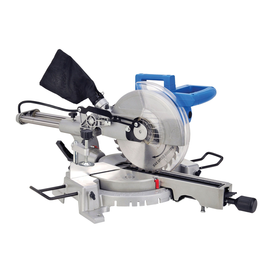
10" Compound Miter Saw
with Laser Guide
Instruction Manual
Model No: 60701380
Read the instructions and precautions before use of this product
Please keep this instruction manual for future reference
For warranty information, please refer to the back page of
this instruction manual.
Advertisement
Table of Contents

Related Manuals for Power Glide 60701380


Summary of Contents for Power Glide 60701380
-
Page 1: Instruction Manual
Consumer Power Tools for Home Use to Original Buyer World Factory, Inc. (Seller) warrants to the original Buyer only, that each POWER GLIDE power tool will be free from defects in material and workmanship for a period of one (1) year from date of purchase. -
Page 2: Important Safety Information
PARTS LIST IMPORTANT SAFETY INFORMATION Description Description Description In this manual, on the labeling, and all other information provided with this product: Bolt Rod Mount Zl102 inner flange 45 Base Cable Clamp 4.2 blade 10"x5/8"x0.110" (30T) This is the safety alert symbol. It is used to alert you to potential personal injury Extend Wing Washer Φ4 outer flange 45... -
Page 3: Assembly Diagram
GENERAL SAFETY RULES ASSEMBLY DIAGRAM WARNING! READ AND UNDERSTAND ALL INSTRUCTIONS. Failure to follow all instructions listed below may result in electric shock and/or serious personal injury. SAVE THESE INSTRUCTIONS 1. KEEP GUARDS IN PLACE and in working order. 2. REMOVE ADJUSTING KEYS AND WRENCHES. Form habit of checking to see that keys and adjusting wrenches are removed from tool before turning it on. -
Page 4: Electrical Safety
ELECTRICAL SAFETY MAINTENANCE Grounding Instructions 5. (SEE FIGURE 24) Use the wrench, turn the 1. (SEE FIGURE 1) All grounded, cord Cover of Grounded Figure 24 blade bolt (1) clockwise to loosen. Unscrew connected tools: In the event of a Outlet Box and remove the bolt. - Page 5 MAINTENANCE SPECIFIC SAFETY RULES FOR MITER SAW 5. Turn the tool off immediately and do not operate, until repaired, if tool begins to make abnormal 1. Do not operate miter saw until it has been assembled and installed according to the "Assembly noise, vibrations, produces smoke or burning odor.
- Page 6 Cutting Bowed or Warped Material SAFETY RULES FOR LASER GUIDE Figure 19 1. (SEE FIGURES 19 & 20) Position warped RIGHT WAY or bowed material, on the miter table CAUTION: LASER RADIATION - Do not stare into the beam. Use of controls or adjustments or TO CUT WARPED MATERIAL with the convex side against the fence.
-
Page 7: Getting To Know Your Tool
Making a Compound Miter Cut GETTING TO KNOW YOUR TOOL A compound miter cut is a cut made using a miter angle and a bevel angle at the same time. This type of cut is used to make picture frames, cut molding, make boxes with sloping sides, and for Figure 2 certain roof framing cuts. -
Page 8: Operation
ASSEMBLY OPERATION Making A Miter Cut Continued CAUTION: The miter saw must be assembled and adjusted before use. DO NOT plug unit into power source until the unit has been completely assembled and all the accuracy IMPORTANT: Before turning on the saw, perform a dry run of the cutting operation. This will make adjustments has been set. - Page 9 Unlocking Saw Cutting Arm The On/Off Trigger Switch Figure 11 Figure 5 CAUTION: Before plugging in the Miter Saw, NOTE: The unit is packaged with the saw arm (2) Saw Arm check the operation of the Trigger (1). Do not in the lock down position.
- Page 10 Adjust the Bevel Angle Figure 8 OPERATION 1. (SEE FIGURE 8) The bevel angle (or Saw Blade (2) Control Arm Assembly tilt capacity) may be adjusted from 0 - 45° to WARNING: RISK OF PERSONAL INJURY. THE ADJUSTMENT KNOBS MUST BE TIGHTENED the left.
Need help?
Do you have a question about the 60701380 and is the answer not in the manual?
Questions and answers
Need to order parts for power glide 10” compound miter saw model number 60701380