
Subscribe to Our Youtube Channel
Summary of Contents for Clare Controls CV-B13D20-ODIW
- Page 1 Network Camera Installation Guide 1.3 MP Budget Mini-Dome Camera Doc ID 2014-11-389 • REV 03...
- Page 3 © 06NOV14 Clare Controls, Inc. All rights reserved. Copyright This document may not be copied in whole or in part or otherwise reproduced without prior written consent from Clare Controls, Inc., except where specifically permitted under US and international copyright law.
-
Page 5: Table Of Contents
Content Description...1 Package contents...1 Safety instruction...1 Overview...4 Installation...6 Before you start...6 Mounting...7 Ceiling mounting...7 Ceiling mounting with gang box...12 Ceiling bracket mounting...14 Wall bracket mounting...16 Installing the micro SD card...18 Setting the network camera over the LAN...20 Accessing via a web browser...24 System requirements...24 Configuring for wireless use...28 Specifications...30... -
Page 7: Description
Description The 1.3 MP Budget Mini-Dome Camera is an affordable PoE 1.3 MP IP mini- dome camera for outdoor use. The fixed-lens camera produces high resolution 1.3 MP output at 1280 × 960 in low illumination with an IR LED range to 10 m. Features include digital wide dynamic range, zone-configurable backlight compensation and a vandal-resistant housing. - Page 8 WARNINGS In the use of the product, you must be in strict compliance with the electrical safety regulations of the nation and region. Refer to the technical specifications for detailed information. Input voltage should meet both the SELV (Safety Extra Low Voltage) and the Limited Power Source with 24 VAC or 12 VDC according to the IEC60950-1 standard.
- Page 9 CAUTIONS Make sure the power supply voltage is correct before using the camera. Do not drop the camera or subject it to physical shock. Do not touch CMOS modules with fingers. If cleaning is necessary, use a clean cloth with a bit of ethanol and wipe it gently.
-
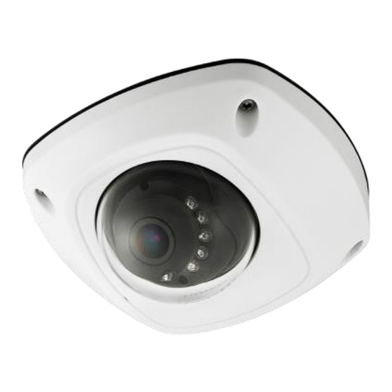
Page 10: Overview
Overview Figure 1: Camera overview... - Page 11 Front cover Audio/alarm cables Dome drive Wi-Fi antenna Micro SD card slot (10) Serial port interface Network cable (11) Hex screw Lens (12) MIC IR LED (13) RESET/WPS button Power cable Notes Press RESET about 10 s when the camera is powering on or rebooting to restore the default settings, including the user name, password, IP address, port No., etc.
-
Page 12: Installation
The link indicator blinks if the wireless connection is successful. Installation To ensure the camera operates properly, install the camera according to the instructions below. Before you start Make sure the device in the package is in good condition and all the assembly parts are included. -
Page 13: Mounting
The foam ring around the lens must be seated flush against the inner surface of the bubble to isolate the lens from the IR LEDS. Fasten the dome cover to camera body so that the foam ring and the dome cover are attached seamlessly. Mounting Ceiling mounting To mount on a ceiling:... - Page 14 Drill Template Hole A :for cables routed through the wall Screw hole1 :for Mounting Base FRONT Code:194101278 Loosen the set screw on the front cover to disassemble the camera with the supplied Allen key. Fix the adapter plate to the ceiling with the supplied expansion screws.
- Page 15 Adapter Plate Side Outlet If the supplied drill template is type II drill template, you can just skip step 3 and go straight to step 4. Fix the dome drive with the supplied screws. Connect the power cable, network cable, and the audio/alarm cables.
- Page 16 View the image via the web browser. Slightly loosen the hex screw beside the WPS/RESET button to adjust the surveillance angle. Use the supplied adjusting tool to adjust the pan [±30°], tilt [0~80°], and rotation direction [0~360°]. Adjusting Tool Rotation Tilt Tighten the hex screw to fix the well-adjusted surveillance angle.
- Page 17 Tear off the protection film softly to complete the installation. Notes Do not tear off the protection film until the installation is completed. Do not touch the inside face of the bubble with your hands.
-
Page 18: Ceiling Mounting With Gang Box
Ceiling mounting with gang box To mount the camera on the ceiling with a gang box: Fix the adapter plate to the gang box with the supplied PM 4 × 8 screws. Fix the dome drive to the adapter plate with the supplied PM 4 ×... - Page 19 Connect the power cable, network cable, and the alarm/audio cables. Align the front cover to the dome drive and tighten the set screws on the front cover. Tear off the protection film softly to complete the installation. Notes: Do not tear off the protection film until the installation is completed.
-
Page 20: Ceiling Bracket Mounting
Ceiling bracket mounting To mount the camera on the ceiling with a bracket: Install the bracket to the ceiling with the supplied screws in the ceiling bracket package. The matched ceiling bracket model is DS-1271ZJ- Note: 120, and you need to purchase it separately the ceiling bracket mounting is used. - Page 21 Align the front cover to the dome drive and tighten the set screws on the front cover to complete the installation. Tear off the protection film softly to complete the installation.
-
Page 22: Wall Bracket Mounting
Notes Do not tear off the protection film until the installation is completed. Do not touch the inside face of the bubble with your hands. Wall bracket mounting To mount the camera on the wall using a bracket: Install the wall bracket to the wall with the supplied screws in the wall bracket package. - Page 23 Fix the dome drive to the wall bracket with the supplied screws. Align the front cover to the dome drive and tighten the set screws on the front cover to complete the installation.
-
Page 24: Installing The Micro Sd Card
Tear off the protection film softly to complete the installation. Notes Do not tear off the protection film until the installation is completed. Do not touch the inside face of the bubble with your hands. Installing the micro SD card To install the micro SD card: Remove the front cover by loosening the set screws. - Page 25 Insert the micro SD card to the card slot until you hear a click. (Optional) Slightly push the inserted micro SD card to uninstall it from the camera. Mirco SD Card...
-
Page 26: Setting The Network Camera Over The Lan
Setting the network camera over the LAN To view and configure the camera via LAN (Local Area Network), you will need to connect the network camera in the same subnet with your PC. Then, install the SADP software to search and change the IP of network camera. The following figure shows the cable connection of network camera and PC. - Page 27 subnet where your computer is located. It displays the total number and information of the searched devices in the Online Devices interface. The interface displays the device type, IP address, port number, and gateway. Notes The device can be searched and displayed in the list 15 seconds after it goes online.
- Page 28 You can click on each column heading to order the information. You can also click to show the device table and hide the network parameter panel on the right side, or click to show the network parameter panel. To modify device information: Select the device to be modified from the device list as shown below.
- Page 29 Edit the modifiable network parameters – for example, IP address and port number. Enter the password of the admin account of the device in the Password field and click Save to save the changes. Enter the IP address of the network camera in the address field of the web browser to view the live video.
-
Page 30: Accessing Via A Web Browser
Accessing via a web browser System requirements Operating System: Microsoft Windows XP SP1 and above version / Vista / Win7 / Server 2003 / Server 2008 32 bits CPU: Intel Pentium IV 3.0 GHz or higher RAM: 1 G or higher ... - Page 31 Install the plug-in before viewing the live video and managing the camera. Follow the installation prompts to install the plug-in. You may need to close the web browser to finish Note: the installation of the plug-in.
- Page 32 Click OK. Click Next.
- Page 33 Click Finish. Reopen the web browser after the installation of the plug- in and repeat steps 2 and 3 to login.
-
Page 34: Configuring For Wireless Use
Configuring for wireless use To connect your mini dome camera for wireless use: Connect the camera to your network with either a powered Ethernet cable, or connect it with an unpowered Ethernet cable and the AC power supply (included). Change the IP settings of your computer to interact with the camera. - Page 35 Click the appropriate security mode and encryption type for your network. If your network is secured with a key or password, enter that key into the Key 1 field. Click Save. Select the TCP/IP tab (in the same menu as the Wi-Fi tab).
-
Page 36: Specifications
Specifications Camera module Image sensor 1/3 in. progressive scan CMOS Image resolution 1280 × 960. Shutter time 1/25 s to 1/100,000 s Illumination 0.01 lux at F1.2, AGC on 0 lux with IR (min.) Lens 24 mm at F2.0, Angle of view: 68° (4 mm) Angle adjustment Pan: ~20°, Tilt: 0°-90°, Rotation: ~90°... - Page 37 System compatibility ONVIF, PSIA, CGI Protocol TCP/IP, HTTP, DHCP, DNS, DDNS, RTP, RTSP, PPPoE, SMTP, NTP, SNMP, HTTPS, FTP, 802.1 ×, QoS, UPnP (SIP, SRTP, optional) SD memory Built-in Micro SD card slot Electrical Power source 12 V DC ± 10%, PoE (802.3a f ) Power consumption Max.
-
Page 38: Regulatory Information
Regulatory information DISCLAIMER Underwriters Laboratories Inc. (UL) has not tested the performance or reliability of the security or signaling aspects of this product. UL has only tested for fire, shock or casualty hazards as outlined in UL’s Standard(s) for Safety, UL60950-1. UL Certification does not cover the performance or reliability of the security or signaling aspects of this product. -
Page 39: Contact Information
(Cd), lead (Pb), or mercury (Hg). For proper recycling, return the battery to your supplier or to a designated collection point. For more information see www.recyclethis.info. Contact information Clare Controls, Inc. 7519 Pennsylvania Ave, Suite 104 Sarasota, FL 34243 Support: 941.404.1072 Fax: 941.870.9646 http://support.clarecontrols.com...
Need help?
Do you have a question about the CV-B13D20-ODIW and is the answer not in the manual?
Questions and answers